
Related Manuals for Kenwood CK 404 G


Summary of Contents for Kenwood CK 404 G
-
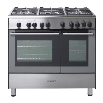
Page 1: Double Oven
DOUBLE OVEN GAS COOKER CK 404 G model Instructions for use - Installation advice Before operating this cooker, please read these instructions carefully... -
Page 2: Table Of Contents
CONTENTS Page Number Introduction ..........Important Safeguards &... -
Page 3: Introduction
Dear Customer, Thank you for purchasing a Kenwood CK 404 G double oven gas cooker. The safety precautions and recommendations reported below are for your own safety and that of others. They will also provide a means by which to make full use of the features offered by your appliance. -
Page 4: Important Safeguards & Recommendations
FIRST USE OF THE OVEN/S It is advised to follow these instructions: • Furnish the interior of the oven/s as described at chapter “Cleaning and maintenan- ce”. • Insert shelf and tray. • Switch on the empty oven/s on max to eliminate grease from the heating ele- ments. - Page 5 and may contain sharp or rough edges, that may cause injury. • Fire risk! Do not store flammable material in the oven/s or in the storage compartment. • Make sure that electrical cables connecting other appliances in the proximity of the cooker cannot come into contact with the hob or become entrapped in the oven door/s. •...
-
Page 6: Cooking Hob
1 - COOKING HOB Fig. 1.1 GAS BURNERS 1. Auxiliary burner (A) 1,00 kW 2. Semi-rapid burner (SR) 1,75 kW 3. Rapid burner (R) 3,00 kW 4. Triple-ring burner (TR) 3,50 kW Notes: • The electric ignition is incorporated in the knobs. •... -
Page 7: Control Panel
2 - CONTROL PANEL Fig. 2.1 CONTROLS DESCRIPTION Front right burner control knob Rear right burner control knob Central burner control knob Rear left burner control knob Front left burner control knob Right small oven: Oven light control knob 120’ alarm knob Left main oven: Oven light control knob Left main oven: Gas oven / gas grill control knob Right small oven: Gas oven control knob... -
Page 8: Use Of The Hob Burners
3 - USE OF THE HOB BURNERS GAS BURNERS Caution! Each burner is controlled by a gas tap as- The cooking hob becomes very hot suring the opening and the closing of the during operation. gas supply. Keep children well out of reach. Make the indicator of the knob match with the symbol on the control panel to obtain: N.B. - Page 9 LIGHTING THE BURNERS CHOICE OF THE BURNER To ignite the burner, the following instruc- On the control panel, near every knob the- tions are to be followed: re is a diagram that indicates which burner Press in the corresponding knob and is controlled by that knob.
-
Page 10: Left Main Gas Oven With Grill
4 - LEFT MAIN GAS OVEN WITH GRILL THERMOSTAT WARNING: The temperature knob is numbered from The door is hot, use the handle. (fig. 4.1) indicating the in- During use the appliance becomes hot. creasing oven temperature value (see ta- Care should be taken to avoid touching ble 4.2). - Page 11 IGNITION OF THE OVEN BURNER ATTENTION: Never turn the control knob before opening the oven door. To light the oven burner operate as follows: Open the oven door to the full extent. WARNING: Risk of explosion! The oven door must be open during this operation.
- Page 12 IGNITION OF THE GRILL BURNER IMPORTANT: The grill must always be used with the oven door ajar and with shield “A” mounted (fig. 4.7). Do not grill with the oven door closed. Attention: The oven door becomes very hot during operation. Keep children away.
- Page 13 USE OF THE GRILL WARNING: Very important: the grill must always be Hot part allow to cool used with the oven door slightly open before removing and with shield “A” mounted (Fig. 4.7). Mount shield “A” which serves to protect the control panel from the heat.
-
Page 14: Right Small Gas Oven
5 - RIGHT SMALL GAS OVEN TEMPERATURE CONTROL WARNING: The temperature knob is numbered from The door is hot, use the handle. (fig. 5.1) indicating the in- During use the appliance becomes hot. creasing oven temperature value (see ta- Care should be taken to avoid touching ble 5.2). - Page 15 IGNITION OF THE OVEN BURNER ATTENTION: Never turn the control knob before opening the oven door. To light the oven burner operate as follows: Open the oven door to the full extent. WARNING: Risk of explosion! The oven door must be open during this operation.
-
Page 16: Cooking Guide
6 - COOKING GUIDE Temperature and times given are approximate, as they will vary depending on the quality and amount of food being cooked. Remember to use ovenproof dishes and to adjust the oven temperature during cooking if necessary. COOKING CHART Temperature Food Cooking Time (approx) -
Page 17: 120 Minute Timer
7 - 120 MINUTE TIMER 120 MINUTE TIMER (Fig. 7.1) The timer can be set to a maximum of 120 minutes and a buzzer will sound at the end of the countdown. The knob must be rotated clockwise as far as the 120 minute position first and then set to the required time by rotating it anti- clockwise. -
Page 18: Cleaning And Maintenance
8 - CLEANING AND MAINTENANCE GENERAL ADVICE ENAMELLED PARTS • Before you begin cleaning, you must All the enamelled parts must be cleaned ensure that the appliance is switched with a sponge and soapy water or other off. non-abrasive products. •... - Page 19 CLEANING THE HOB CORRECT REPLACEMENT OF THE Spillage on the hob can usually be remo- AUXILIARY, SEMI-RAPID AND RAPID ved by a damp soapy cloth. More obstinate BURNERS stains can be removed by rubbing gently It is very important to check that the bur- with a soapy nylon (non metal) scouring ner flame distributor F and the cap C have pad or mild household cleaner.
- Page 20 Fig. 8.1 Fig. 8.2 Fig. 8.3 Fig. 8.4 Fig. 8.5...
- Page 21 INSIDE OF OVEN Fig. 8.6 The oven should always be cleaned after use when it has cooled down. The bottom of the oven, side runner fra- mes, tray and rack can be removed and washed. The cavity should be cleaned using a mild detergent solution and warm water.
- Page 22 Fig. 8.8 Fig. 8.9 OVEN DOORS STORAGE COMPARTMENT The internal glass panel can be easily re- The storage compartment is accessible moved for cleaning by unscrewing the re- through the pivoting panel (fig. 8.9). taining screws (fig. 8.8). Do not use harsh abrasive cleaners or Do not store flammable material in the sharp metal scrapers to clean the oven oven or in the storage compartment.
-
Page 23: Door Assembly
REMOVING THE OVEN DOORS Fig. 8.10a Please operate as follows: • Open the door completely. • Hook the swivel retainers of the rh and lh hinges (fig. 8.10a) onto the metal bar above them (fig. 8.10b). • Hold the door as shown in fig. 8.10. • Gently close the door and withdraw the lower hinge pins from their loca- tion (fig. 8.10c). -
Page 24: Advice For The Installer
Advice for the installer IMPORTANT • The appliance is designed and approved for domestic use only and should not be installed in a commercial, semi commercial or communal environment. The appliance may be installed in a kitchen, Kitchen/diner or a bed sitting room, but not in a room or space containing a bath or a shower. -
Page 25: Installation
9 - INSTALLATION This cooker has class “2/1” overheating protection so that it can be installed next to a cabinet. If the cooker is installed adjacent to furniture which is higher than the gas hob cooktop, a gap of at least 200 mm must be left between the side of the cooker and the furniture. The furniture walls adjacent to the cooker must be made of material resistant to heat. - Page 26 FITTING THE ADJUSTABLE FEET AND LEVELLING THE COOKER The adjustable feet must be fitted to the base of the cooker before use (figs. 9.2, 9.3). Rest the rear of the cooker on a piece of the polystyrene packaging exposing the base for the fitting of the feet. Fit the 4 legs by screwing them tight into the support base as shown in figure 9.3. Fig. 9.2 Fig. 9.3 LEVELLING THE COOKER The cooker may be levelled by screwing the lower ends of the feet IN or OUT (fig.
- Page 27 MOVING THE COOKER WARNING: When raising cooker to upright position always ensure two people carry out this manoeuvre to prevent damage to the adjustable feet (fig. 9.5). Fig. 9.5 WARNING WARNING Be carefull: Do not lift the cooker by When moving cooker to its final po- the door handle/s when raising to sition DO NOT DRAG (fig.
-
Page 28: Stability Bracket
STABILITY BRACKET We recommend a stability bracket is fitted to the cooker. The type shown in fig. 9.8 can be purchased from most plumbers merchants and do it yourself (D.I.Y.) shops. Existing slot in rear of cooker Brackets Dotted line showing the position of cooker when xed Fig. 9.8 Outline of cooker backplate at the engagement slot Wall fixing... -
Page 29: Provision For Ventilation
PROVISION FOR VENTILATION • The appliance should be installed into a room or space with an air supply in accordan- ce with BS 5440-2: 2000. • For rooms with a volume of less than 5m - permanent ventilation of 100 cm free area will be required. -
Page 30: Gas Installation
10 - GAS INSTALLATION IMPORTANT NOTE This appliance is supplied for use on NATURAL GAS or LPG (check the gas regulation label attached on the appliance). • Appliances supplied for use on NATURAL GAS: they are adjusted for this gas only and cannot be used on any other gas (LPG) without modification. The appliances are manufactured for conversion to LPG. - Page 31 GAS CONNECTION The installation of the gas appliance to Natural Gas or LP Gas must be carried out by a suitably qualified and registered installer. Installers shall take due account of the provisions of the relevant British Standards Code of Practice, the Gas Safety Regulations and the Building Standards (Scotland) (Consolida- tion) Regulations issued by the Scottish Development Department.
-
Page 32: Gas Connection
Gas Connection Cat: II 2H3+ The gas supply must use the nearest gas inlet pipe which is located at the left or the right hand side at the rear of the appliance (fig. 10.1). The hose should also be connected in such away that it does not touch the floor. To screw the connecting tube operate with two spanners (fig. 10.2). The unused end inlet pipe must be closed with the plug interposing the gasket. After connecting to the mains, check that the coupling are correctly sealed, using soapy solution, but never a flame. - Page 33 IMPORTANT PRESCRIPTIONS FOR GAS CONNECTION Rear wall Suggested area for Fig. 10.3 gas mains connection...
- Page 34 CONVERSION TO NATURAL GAS OR TO LPG REPLACEMENT OF THE INJEC- Auxiliary, TORS OF THE TOP BURNERS Semi-rapid and If the injectors are not supplied they can Rapid burners be obtained from the After-Sales Service. Select the injectors to be replaced accor- ding to the “Table for the choice of the in- jectors”.
- Page 35 TABLE FOR THE CHOICE OF THE INJECTORS Cat: 2H3+ Natural Gas G30 28-30 mbar G20 20 mbar Nominal Reduced G31 37 mbar BURNERS power power Ø Air ring Ø Air ring [kW] [kW] injector opening injector opening [1/100 mm] [mm] [1/100 mm] [mm] Auxiliary (A)
- Page 36 LEFT OVEN: REPLACEMENT OF THE INJECTOR OF THE OVEN AND GRILL BUR- NERS a) oven burner • Lift and remove the lower panel inside the oven. • Remove the burner securing screw (fig. 10.7). Fig. 10.7 • Withdraw the burner as shown in fi- gure 10.8 and rest it inside the oven.
- Page 37 LEFT OVEN: REGULATION OF AIR SUPPLY TO THE OVEN AND GRILL BURNERS Using a cross-head screwdriver, slacken the screw securing the air flow regulation collar (figs. 10.11, 10.12) and move the collar forward or backward to increase or reduce the air aperture in accordance with gas type and the indications in the “TABLE FOR THE CHOICE OF THE INJECTORS”. Light the burner and check the flame. Fig. 10.11 Fig. 10.12 Ring opening...
- Page 38 RIGHT OVEN: REPLACEMENT OF THE INJECTOR OF THE OVEN BURNER • Lift and remove the lower panel inside the oven. • Remove the 2 screws securing the burner (fig. 10.13). • Withdraw the burner as shown in fi- gure 10.14 and rest it inside the oven. Fig.
- Page 39 LEFT and RIGHT OVENS: REGULATING OF THE OVEN BURNER MINIMUM In the minimum position the flame must have a length of about 4 mm and must re- main lit even with a brusque passage from the maximum position to that of minimum. Left oven: to be effected only for the oven burner (as the grill burner has an only fixed input).
-
Page 40: Electrical Installation
11 - ELECTRICAL INSTALLATION IMPORTANT: The cooker must be installed in accordance with the manufacturer’s instructions. Incorrect installation, for which the manufacturer accepts no respon- sibility, may cause damage to persons, animals and things. The connection of the appliance to earth is mandatory. The manufacturer declines all responsability for any inconvenience resulting from the inobservance of this condition. - Page 41 ELECTRICAL FEEDER CABLE CONNECTION The operations must be executed by a qualified technician. To connect the supply cable: • Remove the screws securing the cover “ A” on the rear of the cooker (fig. 11.2). • Feed the supply cable through the cable clamp “ D” (fig. 11.2). The supply cable must be of a suitable size for the current requirements of the appliance; see the section “Feeder cable section”.
-
Page 42: Guarantee
12 - GUARANTEE UK only If your appliance goes wrong within one year from the date you bought it, we will repair it (or replace it if necessary) free of charge provided: • you have not misused, neglected, or damaged it; •... -
Page 43: After Sales Service
13 - AFTER SALES SERVICE If you require After Sales Service please contact the Currys Product Support Line on 0844 561 6263. Fig. 13.1 Ser. Nr. Descriptions and illustrations in this booklet are given as simply indicative. The manufacturer reserves the right, considering the characteristics of the models described here, at any time and without notice, to make eventual necessary modifications for their construction or for commercial needs. - Page 44 Code: 1103850 - ß1...