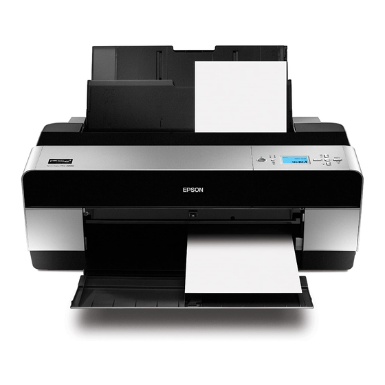
Epson Stylus Pro 3800 Service Manual
Large format color inkjet printer
Hide thumbs
Also See for Stylus Pro 3800:
- User manual (198 pages) ,
- Specifications (12 pages) ,
- Start here manual (6 pages)

Related Manuals for Epson Stylus Pro 3800


Summary of Contents for Epson Stylus Pro 3800
-
Page 1: Service Manual
SERVICE MANUAL Large Format Color Inkjet Printer Epson Stylus Pro 3800/3800C/3850 Epson Stylus Pro 3880/3885/3890 SEIJ06007... - Page 2 The contents of this manual are subject to change without notice. All effort have been made to ensure the accuracy of the contents of this manual. However, should any errors be detected, SEIKO EPSON would greatly appreciate being informed of them.
- Page 3 2. MAKE CERTAIN THAT THE SOURCE VOLTAGES IS THE SAME AS THE RATED VOLTAGE, LISTED ON THE SERIAL NUMBER/RATING PLATE. IF THE EPSON PRODUCT HAS A PRIMARY AC RATING DIFFERENT FROM AVAILABLE POWER SOURCE, DO NOT CONNECT IT TO THE POWER SOURCE.
-
Page 4: Chapter 1 Product Description
Provides Epson-approved methods for adjustment. CHAPTER 6.MAINTENANCE Provides preventive maintenance procedures and the lists of Epson- May indicate an operating or maintenance procedure, practice or approved lubricants and adhesives required for servicing the product. condition that is necessary to accomplish a task efficiently. It may also CHAPTER 7.APPENDIX... - Page 5 Revision Date of Issue Description November 30, 2006 First release • Full-fledged revision September 7, 2009 • Added Epson Stylus Pro 3880/3885/3890. • Chapter 4 April 23, 2010 "REASSEMBLY" of 4.3.3.15 BASE, ENCLOSURE was added. "CAUTION" of 4.3.9.2 COVER, CR was added.
-
Page 6: Table Of Contents
Epson Stylus Pro 3800/3800C/3850/3880/3885/3890 Revision C Contents Chapter 1 PRODUCT DESCRIPTION Chapter 2 OPERATING PRINCIPLES 1.1 Product Description .................... 10 2.1 Overview ......................36 1.2 Basic Specifications .................... 11 2.2 Print Mechanism ....................40 1.2.1 Basic Specifications ................... 11 2.3 Ink Supply Mechanism ..................41 1.2.2 Electric Specifications ................ - Page 7 Epson Stylus Pro 3800/3800C/3850/3880/3885/3890 Revision C 3.5 Remedies for Service Call Error ................. 74 5.2 Mechanical Adjustment ..................217 5.2.1 PF Timing Belt Tension Adjustment ............217 3.6 Remedies for Print Quality Troubles ..............82 5.2.2 LD Roller Position Adjustment ............... 219 5.2.3 PG Position Adjustment ................
- Page 8 Epson Stylus Pro 3800/3800C/3850/3880/3885/3890 Revision C Chapter 6 MAINTENANCE 6.1 Overview ......................270 6.2 Product Life Information .................. 271 6.3 Cleaning ......................272 6.4 Lubrication ....................... 273 Chapter 7 APPENDIX 7.1 Connectors ......................283 7.2 Cables Connection Layout ................285 7.3 ASP List ......................
- Page 9 C H A P T E R PRODUCT DESCRIPTION...
-
Page 10: Product Description
Epson Stylus Pro 3800/3800C/3850/3880/3885/3890 Revision C 1.1 Product Description Epson Stylus Pro 3800/3800C/3850/3880/3885/3890 are large size color inkjet printers that support up to A2 (17”) sized cut-sheet paper. F-Mach (180N x 8-column) print head Maximum print resolution (dpi): 2880 x 1440, Minimum dot: 3.5pl MSDT... -
Page 11: Basic Specifications
Epson Stylus Pro 3800/3800C/3850/3880/3885/3890 Revision C 1.2 Basic Specifications Table 1-1. Cartridge Alignment Sequence Row 1 Row 2 Row 3 Row 4 Row 5 Row 6 Row 7 Row 8 Row 9 Epson Stylus Pro 3800/3800C/3850 1.2.1 Basic Specifications Light... -
Page 12: Electric Specifications
Epson Stylus Pro 3800/3800C/3850/3880/3885/3890 Revision C 1.2.2 Electric Specifications 1.2.3 Environmental Characteristics Specification TEMPERATURE/HUMIDITY Item 100/120V Model 220/240V Model Humidity Rated voltage 100 to 120 VAC 220 to 240 VAC Condition Temperature (non condensation) Input voltage range 90 to 132 VAC... -
Page 13: Reliability/Durability
Epson Stylus Pro 3800/3800C/3850/3880/3885/3890 Revision C 1.2.4 Reliability/Durability RESISTANCE TO VIBRATION/SHOCK Item Target Vibration Shock Until any one of the following conditions is met. Operating 0.15G, 10 to 55Hz 1G, within 1ms • 12,000 pages (A2 plain paper fine mode) Storage 0.50G, 10 to 55Hz... -
Page 14: Printing Specifications
25.4 mm (1 inch) when line feed: 333 msec (3 inch/sec) 1.3.2 Paper Feeder Specifications Epson Stylus Pro 3800/3800C/3850/3880/3885/3890 support three types of paper feeding methods; ASF, Rear Manual Feed, and Front Manual Feed. The paper size and thickness for each of the methods are shown in the table below. For paper type and feeder capacity, refer to "1.3.3 Paper Support"... -
Page 15: Paper Support
Epson Stylus Pro 3800/3800C/3850/3880/3885/3890 Revision C 1.3.3 Paper Support Feeder Borderless Black Media Name Size (mm) EAI EU Asia (capacity* print* Ink* Feeder Borderless Black √ √ Letter (216x279) ASF (20) Media Name Size (mm) EAI EU Asia (capacity* print* Ink* √... -
Page 16: Printable Area
Epson Stylus Pro 3800/3800C/3850/3880/3885/3890 Revision C 1.3.4 Printable Area Item Dimension PW (paper width) 89mm to 431.8mm PL (paper length) 127mm to 950mm TM (top margin) 0mm/3mm/20mm* BM (bottom margin) 0mm/3mm/20mm* LM (left margin) 0mm/3mm RM (right margin) 0mm/3mm Note *: TM and BM are fixed to 20 mm in front manual feeding. -
Page 17: Print Mode
Epson Stylus Pro 3800/3800C/3850/3880/3885/3890 Revision C 1.4 Print Mode Table 1-5. Borderless Printing Available Paper Sizes Paper Size Displayed by Driver Borderless Print This section provides specifications of the print mode and borderless printing. A4 (210 x 297 mm) Available... - Page 18 Epson Stylus Pro 3800/3800C/3850/3880/3885/3890 Revision C AUTOMATIC EXPANSION SPECIFICATION PRINTABLE AREA The driver automatically changes margins that bleed off the edges of paper according Printing position coordinate origin to the paper size. Width-direction printable area Table 1-6. Borderless Printing Margins (Bleed) 3.5m (max)
-
Page 19: Appearance Specifications
Epson Stylus Pro 3800/3800C/3850/3880/3885/3890 Revision C 1.5 Appearance Specifications Dimensions Storage: 684 (W) x 376 (H) x 257 (D) mm Printing: 684 (W) x 1040 (H) x 550 (D) mm This section describes external dimensions and parts names. Weight 1.5.1 Dimensions/Weight 18.5 kg (excluding ink cartridges, including Maintenance cartridge) -
Page 20: Operation Panel
Epson Stylus Pro 3800/3800C/3850/3880/3885/3890 Revision C 1.6 Operation Panel Functions Button Hold Down for Function at the Normal One Press 3 Seconds Panel Setting 1.6.1 Buttons and Functions • When paper is set ASF: Ejects the paper Power LED Back/Left... -
Page 21: Panel Display
Epson Stylus Pro 3800/3800C/3850/3880/3885/3890 Revision C Error indication Note *: Alternately turns On and Off every 500 ms. In the case of maintenance call error, they light for 100 ms at intervals of five seconds. Note : When a service call error occurs, all the LEDs flash. -
Page 22: Icons On The Lcd
The indicators below is displayed when Ink becomes Low or Out. WIDER is selected. Note : The following table is for Epson Stylus Pro 3800/3800C/3850. In the case of Epson Stylus Pro 3880/3885/3890, M is VM and LM is VLM. WIDEST is selected. - Page 23 Epson Stylus Pro 3800/3800C/3850/3880/3885/3890 Revision C MAINTENANCE CARTRIDGE STATUS Maintenance Cartridge Counter The free space of the Maintenance Cartridge is indicated as shown below. Figure 1-12. Maintenance Cartridge Status Table 1-8. Relation between Counters and Remaining Ink Free Space Free Space...
-
Page 24: Menu Settings
Epson Stylus Pro 3800/3800C/3850/3880/3885/3890 Revision C 1.6.6 Menu Settings Table 1-9. List of Menu Settings Top Menu Menu Items Settings (Bold = default) Explanation NARROW STANDARD Adjusts the gap between the print head and the platen. The set value is returned to the default at every power-on. - Page 25 Paper type and relating settings can be saved and easily retrieved by assigning a number to them. Up to 10 groups of PAPER NUMBER (1-10) settings can be stored. When EPSON genuine paper is used, STANDARD should be selected. PAPER NO.1-10...
- Page 26 Epson Stylus Pro 3800/3800C/3850/3880/3885/3890 Revision C Table 1-9. List of Menu Settings Top Menu Menu Items Settings (Bold = default) Explanation DISABLE Disables or enables a network connection. The other NETWORK SETUP menu items appear only when ENABLE has been selected. Under the following conditions, this setting is automatically changed to DISABLE.
- Page 27 Epson Stylus Pro 3800/3800C/3850/3880/3885/3890 Revision C PG settings list Firmware version indication The table below lists the platen gap amounts settable with the printer driver, control The table below explains the meaning of the “o0XXXX-xx.xx.IBC” (firmware panel, and media table.
-
Page 28: Maintenance Mode
Epson Stylus Pro 3800/3800C/3850/3880/3885/3890 Revision C 1.6.7 Maintenance Mode HOW TO START & QUIT Starting Method Turn the printer On while holding down the Cancel/Reset button. Quitting Method Turn the printer Off. MAINTENANCE MODE MENU LIST Settings Menu Item Explanation... -
Page 29: Error/Warning Statuses Displayed/Indicated On/By Lcd/Led
Epson Stylus Pro 3800/3800C/3850/3880/3885/3890 Revision C 1.6.8 Error/Warning Statuses Displayed/Indicated on/by LCD/LED Error or Illustration Error/Warning Status Message on LCD Warning on LCD Power Paper Status Ink Status SERVICE CALL ERROR NNNN FATAL ERROR (Service Call No. is displayed) Error... - Page 30 Epson Stylus Pro 3800/3800C/3850/3880/3885/3890 Revision C Error or Illustration Error/Warning Status Message on LCD Warning on LCD Power Paper Status Ink Status Paper Jam Discharge Failed PAPER JAM Error Light Light Remove Paper REMOVE PAPER RELEASING THE Waiting Cartridge Cover open...
- Page 31 Epson Stylus Pro 3800/3800C/3850/3880/3885/3890 Revision C Error or Illustration Error/Warning Status Message on LCD Warning on LCD Power Paper Status Ink Status FRONT FEED SLOT OPEN PRESS THE Board paper removal error Error DOWN BUTTON Light Light AND REMOVE PAPER...
- Page 32 Epson Stylus Pro 3800/3800C/3850/3880/3885/3890 Revision C Error or Illustration Error/Warning Status Message on LCD Warning on LCD Power Paper Status Ink Status INK CARTRIDGE Ink End Error Light Light REPLACE INK CARTRIDGE INK COVER OPEN Ink Cover Open Error Light...
- Page 33 Epson Stylus Pro 3800/3800C/3850/3880/3885/3890 Revision C Error or Illustration Error/Warning Status Message on LCD Warning on LCD Power Paper Status Ink Status PAPER ERROR No Paper Error Light Light LOAD PAPER PAPER SIZE ERROR Paper Size Check Error Error LOAD THE CORRECT SIZE...
- Page 34 Epson Stylus Pro 3800/3800C/3850/3880/3885/3890 Revision C Error or Illustration Error/Warning Status Message on LCD Warning on LCD Power Paper Status Ink Status MAINTENANCE COVER OPEN Maintenance Cartridge Cover Open Warning Warning CLOSE THE Light Blink MAINTENANCE COVER REPLACE MAINTENANCE Maintenance Cartridge Low...
- Page 35 C H A P T E R OPERATING PRINCIPLES...
-
Page 36: Overview
Epson Stylus Pro 3800/3800C/3850/3880/3885/3890 Revision C 2.1 Overview OPERATING PRINCIPLES OVERVIEW 2.5 Carriage Mechanism 2.6 Paper Feed Mechanism Explains how paper is fed and Explains how to move the Carriage Unit. transported. <Main Components> <Main Components> • CR Motor • PF Motor •... - Page 37 Epson Stylus Pro 3800/3800C/3850/3880/3885/3890 Revision C MAIN COMPONENT Electric Circuit Boards Table 2-1. List of Electric Circuit Boards Fig. Name Function Communications with host computer Receive data processing Main board Epson Stylus Pro 3800/3800C/ Engine control 3850: C635 MAIN Saves compensation values and various counter Epson Stylus Pro 3880/3885/ information.
- Page 38 Epson Stylus Pro 3800/3800C/3850/3880/3885/3890 Revision C Motors/Solenoid Table 2-2. List of Motors/Solenoid Driven Parts Fig. Name Specifications Release roller Release motor Type: DC motor ± Voltage:42 VDC PF roller Paper eject roller A PF motor Paper eject roller B Type: DC motor ±...
- Page 39 Epson Stylus Pro 3800/3800C/3850/3880/3885/3890 Revision C Sensors/Encoders/CSIC Table 2-3. List of Sensors/Encoders/CSIC Fig. Name Function Specifications Table 2-3. List of Sensors/Encoders/CSIC Detects a rear edge of Type: Transmissive photo interrupter PE sensor Fig. Name Function Specifications ± paper. Voltage: 3.3 VDC...
-
Page 40: Print Mechanism
Epson Stylus Pro 3800/3800C/3850/3880/3885/3890 Revision C 2.2 Print Mechanism Table 2-4. Nozzle Rows and Colors Color Nozzle Row This section explains the basic specifications of the print head. Epson Stylus Pro 3800/3800C/3850 Epson Stylus Pro 3880/3885/3890 Magenta Vivid Magenta NOZZLE CONFIGURATION AND COLORS... -
Page 41: Ink Supply Mechanism
Epson Stylus Pro 3800/3800C/3850/3880/3885/3890 Revision C 2.3 Ink Supply Mechanism 2.3.2 Ink Pressurizing Mechanism This printer employs an ink pressurizing mechanism to stably supply ink in the ink 2.3.1 Ink Flow Path cartridge (ink pack) to the print head. This ink pressurizing mechanism consists of a pressure pump unit installed in an ink supply mechanism and tightly-sealed ink The ink flow path is shown below. - Page 42 Epson Stylus Pro 3800/3800C/3850/3880/3885/3890 Revision C 2.3.2.1 Pressure Pump Unit Mechanism Applying pressure Clutch Valve Accordion unit/Pressure pump motor/Pressure pump home sensor CW rotation of the The accordion unit intakes air and applies pressure by the rotating drive of the pressure clutch closes the valve pump motor, and pumps air into the ink cartridges.
-
Page 43: Ink Change System
Epson Stylus Pro 3800/3800C/3850/3880/3885/3890 Revision C 2.3.3 Ink Change System This printer has automatic ink change system that switches black ink between Photo Black and Matte Black. The cartridge holder of this printer keeps both Photo Black and Changing to Matte Black Changing to Photo Black Matte Black ink cartridges. -
Page 44: Cleaning Mechanism
Epson Stylus Pro 3800/3800C/3850/3880/3885/3890 Revision C 2.4 Cleaning Mechanism Cap Unit/Carriage Lock The pump motor moves the cap unit up and down. The cap unit goes up to seal the print head during cleaning and stand-by. Carriage lock operates in synchronization The cleaning mechanism consists of a pump cap unit and a waste ink pads (maintenance cartridge). - Page 45 Epson Stylus Pro 3800/3800C/3850/3880/3885/3890 Revision C Pump Unit Head Cleaner The ink is absorbed from the head nozzles. The sucked waste ink is conveyed to the The head cleaner wipes off ink, dirt or the like from the surface of the head nozzles.
-
Page 46: Carriage Mechanism
Epson Stylus Pro 3800/3800C/3850/3880/3885/3890 Revision C 2.5 Carriage Mechanism The carriage mechanism consists of a carriage movement mechanism, platen gap adjustment mechanism, and carriage lock mechanism. For explanation about the CR Scale carriage lock mechanism, refer to Cap Unit/Carriage Lock (p.44). -
Page 47: Platen Gap Adjustment Mechanism
Epson Stylus Pro 3800/3800C/3850/3880/3885/3890 Revision C 2.5.2 Platen Gap Adjustment Mechanism Table 2-7. PG Positions in Operations Operation Platen gap adjustment mechanism consists of an APG motor, carriage unit, and PG sensor. Detecting paper width The carriage unit is equipped with two carriages; main carriage that moves horizontally to (ASF feeding, Rear/Front manual feeding) the carriage guide shaft, and the sub carriage that moves vertically to the main carriage. -
Page 48: Paper Feed Mechanism
Epson Stylus Pro 3800/3800C/3850/3880/3885/3890 Revision C 2.6 Paper Feed Mechanism 2.6.1 Paper Feed Path The printer provides two manual paper feed paths in addition to the ASF to support thicker paper. Paper Feeding Thickness Type ASF (Auto Sheet Feeder) 0.08 to 0.27 mm 1.3.3 Paper Support (p.15) -
Page 49: Paper Loading Mechanism
Epson Stylus Pro 3800/3800C/3850/3880/3885/3890 Revision C 2.6.2 Paper Loading Mechanism 2-2. The LD roller shaft rotates to release the hopper actuating the cam that presses the hopper, and the hopper moves up by the tension of the spring. ASF (AUTO SHEET FEEDER) - Page 50 Epson Stylus Pro 3800/3800C/3850/3880/3885/3890 Revision C Pressing the hopper Standing-by The hopper cam on the LD roller shaft presses the hopper and remaining paper on The hopper returns to the stand-by position and ends the paper loading operation. the tray is moved away from the feeding position.
- Page 51 Epson Stylus Pro 3800/3800C/3850/3880/3885/3890 Revision C REAR MANUAL BYPASS When the prescribed time has passed since a paper was supplied from the feeder on the rear of the printer and the PE sensor detected the paper, the PF roller starts to transport the paper.
-
Page 52: Paper Feed Mechanism
Epson Stylus Pro 3800/3800C/3850/3880/3885/3890 Revision C 2.6.3 Paper Feed Mechanism The paper feed mechanism mainly consists of a Release mechanism, the PF Motor, and Release Motor the feed rollers. Combination Gear, 9.6, 22 RELEASE MECHANISM Spur Gear, 22 Release mechanism consists of a release unit (including a release motor, release sensor, and combination gear), paper guide upper assy that presses papers, and paper guide release shaft that activates the paper guide upper assy. - Page 53 Epson Stylus Pro 3800/3800C/3850/3880/3885/3890 Revision C Paper Guide Upper Assy Paper Guide Release Shaft Spur Gear, 22 Release Motor Combination Gear, 8, 22 PF Roller Combination Gear, 9.6, 22 Spur Gear, 20.4 Combination Gear, 8, 22.986 Release Sensor Light-shielding Plate...
- Page 54 Epson Stylus Pro 3800/3800C/3850/3880/3885/3890 Revision C PAPER FEED MECHANISM Paper feed mechanism consists of a PF motor, PF scale, PF encoder, PF roller, front and rear paper eject rollers, and star wheels. The mechanism transports papers fed from the feeders and ejects them from the front of the printer.
- Page 55 Epson Stylus Pro 3800/3800C/3850/3880/3885/3890 Revision C Frame, EJ Assy Paper Star Wheel Front Paper Eject Roller Rear Paper Eject Roller PF Roller Spur Gear, 14.4 PF Encoder Spur Gear, 68 Spur Gear, 31.5 PF Motor PF Scale PF Timing Belt Combination Gear, PF, Drive Figure 2-30.
-
Page 56: Ink Mark Sensor
Epson Stylus Pro 3800/3800C/3850/3880/3885/3890 Revision C 2.7 Ink Mark Sensor This printer is equipped with the ink mark sensor functioning as multi sensors. The sensor, located on the bottom of the carriage unit, is a diffuse reflective photointerruptor that is comprised of a light emitting part (white LED) and a light receiving part (photoreceiver). -
Page 57: Other Mechanisms
Epson Stylus Pro 3800/3800C/3850/3880/3885/3890 Revision C 2.8 Other Mechanisms MAINTENANCE CARTRIDGE COVER OPEN DETECTION To keep the maintenance cartridge from being removed during printing, a switch INK COVER OPEN-CLOSE MECHANISM sensor detects opening/closing state of the cover that stores the maintenance cartridge. -
Page 58: Outline Of Circuit Boards
(IC3) CR Motor DDR-SDRAM CN43 (IC19) A6628 (IC13) This section provides a summary of the main board (Epson Stylus Pro 3800/3800C/ ASF Motor Flash ROM (IC4) CN44 3850: C653 MAIN / Epson Stylus Pro 3880/3885/3890: CA61 MAIN) that controls the... -
Page 59: Power Supply Board
Epson Stylus Pro 3800/3800C/3850/3880/3885/3890 Revision C 2.9.2 Power Supply Board This section describes the power supply board that generates the power to operate this printer. CIRCUIT BLOCK DIAGRAM The block diagram of C635 Power Supply board is shown below. Pseudo-resonance type Input Filter +42V/0.7A... -
Page 60: Colorimetric Calibration (Color Id) Overview
Epson Stylus Pro 3800/3800C/3850/3880/3885/3890 Revision C 2.10 Colorimetric Calibration (Color ID) Overview Main Unit This printer employs “Colorimetric Calibration (Color ID)” to correct unit-to-unit variations in color. Power Supply Colorimetric Calibration (Color ID) corrects not only the weight of ink droplets which... -
Page 61: Chapter 3 Trouble Shooting
C H A P T E R TROUBLE SHOOTING... -
Page 62: Overview
Epson Stylus Pro 3800/3800C/3850/3880/3885/3890 Revision C 3.1 Overview When handling the lithium battery used for backup of the RTC on W A R N I N G the main board, strictly follow the safety instructions given in This section explains the basic procedure for troubleshooting problems on the printer “4.1.1 Precautions”... -
Page 63: List Of Panel Messages
Epson Stylus Pro 3800/3800C/3850/3880/3885/3890 Revision C 3.2 List of Panel Messages Table 3-1. List of Panel Messages Ref. Category Message on LCD Description Page The printer runs diagnostic checks on itself according to various conditions detected by PAPER FEED ERROR Failed to feed board paper into the the mounted sensors. - Page 64 Description Category Message on LCD Description Page Page FRONT FEED SLOT OPEN A board paper could not be INK CARTRIDGE The ink cartridge is not an EPSON- PRESS THE removed. genuine one. DOWN NON-GENUINE BUTTON CARTRIDGE! AND REMOVE QUALITY OF...
- Page 65 Epson Stylus Pro 3800/3800C/3850/3880/3885/3890 Revision C Table 3-1. List of Panel Messages Ref. Category Message on LCD Description Page PAPER FEED ERROR A multi-feed was detected and the LOAD PAPER papers were ejected automatically CORRECTLY without printing. PRESS THE DOWN BUTTON...
-
Page 66: Remedies For Warning Messages
Epson Stylus Pro 3800/3800C/3850/3880/3885/3890 Revision C 3.3 Remedies for Warning Messages When a Warning error occurs, the printer displays a Warning message instead of “READY” or “PRINTING” messages, however, it does not interfere with printing operation. REMEDIES The following tables explains the Warning messages and remedies. - Page 67 Epson Stylus Pro 3800/3800C/3850/3880/3885/3890 Revision C MAINTENANCE REQUEST XXXX When a Maintenance Request error occurs, the printer displays on the LCD a hexadecimal code of “NNNN” which correspond to the bit numbers assigned to error statuses as shown in the table below.
-
Page 68: Remedies For Error Messages
Epson Stylus Pro 3800/3800C/3850/3880/3885/3890 Revision C 3.4 Remedies for Error Messages The following tables explains the error messages and remedies. Message on LCD Description Remedy SERVICE CALL ERROR See 3.5 Remedies for Service Call Error on page 74. NNNN PLEASE CONTACT TO THE... - Page 69 Replace the ink cartridge with a new one. REPLACE INK CARTRIDGE WITH A NEW ONE MAINTENANCE The installed maintenance cartridge is not the EPSON genuine cartridge. Replace the maintenance cartridge with an EPSON genuine one. PLEASE USE GENUINE EPSON CARTRIDGES MAINTENANCE The installed maintenance cartridge is not the EPSON genuine cartridge.
- Page 70 Check the connection between the CSIC and the main board, and fix any REPLACE CARTRIDGE abnormality. Replace the ink cartridge. INK CARTRIDGE The installed ink cartridge is not the EPSON genuine cartridge. Replace the ink cartridge with an EPSON genuine one. PLEASE USE GENUINE EPSON INK CARTRIDGE TROUBLE SHOOTING...
- Page 71 Epson Stylus Pro 3800/3800C/3850/3880/3885/3890 Revision C Message on LCD Description Remedy INK CARTRIDGE The installed ink cartridge is not the EPSON genuine cartridge. After selecting “NO”, replace the ink cartridge with a genuine one. NON-GENUINE CARTRIDGE! QUALITY OF NON-GENUINE INK MAY VARY.
- Page 72 Epson Stylus Pro 3800/3800C/3850/3880/3885/3890 Revision C Message on LCD Description Remedy BORDERLESS ERROR The paper edges are not on the Porous Pad because the size of the loaded paper Press the Paper Feed/Down button to eject the paper. PRESS THE DOWN BUTTON is not supported for borderless printing.
- Page 73 Epson Stylus Pro 3800/3800C/3850/3880/3885/3890 Revision C Message on LCD Description Remedy PAPER SENSOR ERROR An error has occurred while the Ink Mark sensor is reading the print pattern for Press the Cancel/Reset button and load a different type of paper.
-
Page 74: Remedies For Service Call Error
Epson Stylus Pro 3800/3800C/3850/3880/3885/3890 Revision C 3.5 Remedies for Service Call Error The following tables explains the Service Call error messages and remedies. Make sure to check the related connectors and cables for poor C H E C K P O I N T connection or any abnormality before replacing any electrical part as instructed in the Remedy column. - Page 75 Epson Stylus Pro 3800/3800C/3850/3880/3885/3890 Revision C Error Code Error Name Description Remedy 1123 Duty over error An abnormal load is applied to the CR motor. Check the carriage shaft surface for any foreign matters, and remove it if any. Check that the carriage shaft and the contact points between the carriage unit and the main frame are properly lubricated.
- Page 76 Epson Stylus Pro 3800/3800C/3850/3880/3885/3890 Revision C Error Code Error Name Description Remedy 1134 Integral term overload (PID-load An abnormal load is applied to the CR motor. Check the carriage shaft surface for any foreign matters, and positioning) remove it if any.
- Page 77 Epson Stylus Pro 3800/3800C/3850/3880/3885/3890 Revision C Error Code Error Name Description Remedy 1225 Positioning time-out The PF roller cannot be rotated to the specified point. Check that the PF timing belt is properly attached. Check the PF timing belt’s tension. Correct it if not proper.
- Page 78 Epson Stylus Pro 3800/3800C/3850/3880/3885/3890 Revision C Error Code Error Name Description Remedy 1410 Drive time monitor time-out (PUMP) The Pump motor run away out of control. Turn the printer power On and Off. Replace the main board (BOARD ASSY., MAIN).
- Page 79 Epson Stylus Pro 3800/3800C/3850/3880/3885/3890 Revision C Error Code Error Name Description Remedy 150C PF phase detection error The APG sensor cannot detect the origin point when the APG Replace the APG motor (MOTOR, ASSY, APG). motor has driven for a predetermined time period.
- Page 80 Epson Stylus Pro 3800/3800C/3850/3880/3885/3890 Revision C Error Code Error Name Description Remedy 1A37 Thermistor sensor error The head FFC is not correctly connected. Check the head FFC, and reconnect it correctly. The head thermistor detected the head temperature fell outside the Replace the print head.
- Page 81 Epson Stylus Pro 3800/3800C/3850/3880/3885/3890 Revision C Error Code Error Name Description Remedy DXXX Error code for debugging The main board is broken. Replace the main board (BOARD ASSY., MAIN). See 4.3.4.1 BOARD ASSY., MAIN on page 113. There is something wrong with the firmware.
-
Page 82: Remedies For Print Quality Troubles
Epson Stylus Pro 3800/3800C/3850/3880/3885/3890 Revision C 3.6 Remedies for Print Quality Troubles This section provides troubleshooting of print quality troubles classifying them by observed symptom. Symptom Description Remedy Dot missing The nozzles are clogging with ink. Clear the clogged nozzles following the procedure below. - Page 83 Epson Stylus Pro 3800/3800C/3850/3880/3885/3890 Revision C Symptom Description Remedy Ink smear (backside) Paper is curled or creased. Change the paper with a normal one. The paper is contaminated by ink smear in the paper feed path. Check the platen and PF roller for ink smudges, and clean them if any dirt is observed.
- Page 84 Epson Stylus Pro 3800/3800C/3850/3880/3885/3890 Revision C Symptom Description Remedy Vertical banding (overall) Bi-D and Uni-D adjustments have not been carried out properly. Carry out the Auto Bi-D and the Auto Uni-D adjustments. See Chapter 5 "ADJUSTMENT". The carriage unit cannot move smoothly.
- Page 85 C H A P T E R DISASSEMBLY & ASSEMBLY...
-
Page 86: Overview
Epson Stylus Pro 3800/3800C/3850/3880/3885/3890 Revision C 4.1 Overview 4.1.1 Precautions Before starting disassembly or reassembly of the product, read the following This section describes procedures for disassembling the main components of the precautions given under the headings “WARNING” and “CAUTION”. - Page 87 Epson Stylus Pro 3800/3800C/3850/3880/3885/3890 Revision C Always wear gloves for disassembly and reassembly to avoid When reassembling the printer, make sure to route the FFCs W A R N I N G C A U T I O N injury from sharp metal edges.
-
Page 88: Orientation Definition
Epson Stylus Pro 3800/3800C/3850/3880/3885/3890 Revision C 4.1.2 Orientation Definition 4.1.3 Tools The following figure defines the orientation of the printer, which is applicable to To protect the printer from damage, use the tools indicated in the following table. chapter 4. -
Page 89: Screws
Epson Stylus Pro 3800/3800C/3850/3880/3885/3890 Revision C 4.1.4 Screws 4.1.5 Chapter Organization The following table indicates the screws used in the printer. The maintenance parts of this product are classified into two groups according to the site they are repaired. Therefore, disassembling procedures are divided into two groups Table 4-2. -
Page 90: Note On The Compatibility Of Parts
2113738 1520869 p123 INK,SYSTEM,ASSY.,ESL,ASP 1451573 1518586 p153 PRINT HEAD F177000 F196000 p161 Note : MOTOR ASSY.,CR,CS is the part name for Epson Stylus Pro 3800/3800C/3850. The part name for Epson Stylus Pro 3880/3885/3890 is MOTOR ASSY.,CR,ASP. DISASSEMBLY & ASSEMBLY Overview... -
Page 91: Disassembly Flowchart
Epson Stylus Pro 3800/3800C/3850/3880/3885/3890 Revision C 4.2 Disassembly Flowchart Parts shown in the dotted-line boxes are not the shortest procedures to Start remove them, but are necessary to proceed to the next step. Group 1 COVER, IH, ASSY. (p95) HOUSING, REAR, ASSY. (p96) -
Page 92: Disassembly/Assembly Procedure (Group 1)
Epson Stylus Pro 3800/3800C/3850/3880/3885/3890 Revision C 4.3 Disassembly/Assembly Procedure (Group 1) This section describes disassembly/assembly procedures required for both on-site and off-site servicing. 4.3.1 Unlocking the CARRIAGE, ASSY. manually Carriage Lock Release Gear Remove the HOUSING, RIGHT. (p104) While pressing the carriage lock release gear in the direction of the arrow, turn it counterclockwise until it stops to unlock the CARRIAGE, ASSY. -
Page 93: Consumable
Epson Stylus Pro 3800/3800C/3850/3880/3885/3890 Revision C 4.3.2 Consumable Ink Cover Open/UP Button 4.3.2.1 Ink Cartridge Turn the printer ON. COVER, IH, ASSY. Hold down the Ink Cover Open/Up button on the operation panel for more than three seconds. The COVER, IH, ASSY. will be unlocked and slightly opened. - Page 94 Epson Stylus Pro 3800/3800C/3850/3880/3885/3890 Revision C 4.3.2.2 Maintenance Cartridge Open the COVER, WB. Slightly lift the Maintenance Cartridge and pull it out from the main unit. Never touch the IC chip on the Maintenance Cartridge. Doing so C A U T I O N may cause a detection error of the Maintenance Cartridge or a malfunction of the printer.
-
Page 95: Removing The Housing And Operation, Panel, Assy
Epson Stylus Pro 3800/3800C/3850/3880/3885/3890 Revision C 4.3.3 Removing the Housing and OPERATION, PANEL, ASSY. guide pin guide pin 4.3.3.1 COVER, IH, ASSY. As the COVER, IH, ASSY is locked by the electric system, be sure C A U T I O N to open the COVER, IH, ASSY. - Page 96 Epson Stylus Pro 3800/3800C/3850/3880/3885/3890 Revision C 4.3.3.2 HOUSING, REAR, ASSY. Remove the five screws that secure the HOUSING, REAR, ASSY. and remove it. HOUSING, REAR, ASSY. Four C.B.P. 3 x 6 screws (6 ± 1 kgf.cm) One C.B.S. 3 x 8 screw (6 ± 1 kgf.cm) C.B.S.
- Page 97 Epson Stylus Pro 3800/3800C/3850/3880/3885/3890 Revision C Install the HOUSING, REAR, ASSY. so that all the points mentioned below are securely engaged. Fig. Position of the points Main unit HOUSING, REAR, ASSY. Right side Two positioning holes Two guide pins Right side...
- Page 98 Epson Stylus Pro 3800/3800C/3850/3880/3885/3890 Revision C 4.3.3.3 HOUSING, FRONT, LEFT Open the STACKER, C. Remove the screw that secures the HOUSING, FRONT, LEFT to the main unit. One C.B.P. 3 x 8 screw (6 ± 1 kgf.cm) Pull the upper part of the HOUSING, FRONT, LEFT toward you to release the upper rib and the two lower hooks, and remove the HOUSING, FRONT, LEFT.
- Page 99 Epson Stylus Pro 3800/3800C/3850/3880/3885/3890 Revision C 4.3.3.4 HOUSING, FRONT, RIGHT Open the STACKER, C. Remove the screw that secures the HOUSING, FRONT, RIGHT to the main unit. One C.B.P. 3 x 8 screw (6 ± 1 kgf.cm) Pull the upper part of the HOUSING, FRONT, RIGHT toward you to release the upper rib and the two lower tabs, and remove the HOUSING, FRONT, RIGHT.
- Page 100 Epson Stylus Pro 3800/3800C/3850/3880/3885/3890 Revision C 4.3.3.5 COVER, PRINTER Open the COVER, PRINTER. Widen the parts shown in Figure 4-11 to release the COVER, PRINTER from the two bosses (left and right), and remove the COVER, PRINTER. COVER, PRINTER Figure 4-11. Removing the COVER, PRINTER DISASSEMBLY &...
- Page 101 Epson Stylus Pro 3800/3800C/3850/3880/3885/3890 Revision C 4.3.3.6 PAPER, SUPPORT, MANUAL, ASSY. Remove the PAPER, SUPPORT, MANUAL, ASSY. upward. Be sure to engage all the hooks (two on the upper part , five on the lower part ) of the PAPER, SUPPORT, MANUAL, ASSY.
- Page 102 Epson Stylus Pro 3800/3800C/3850/3880/3885/3890 Revision C 4.3.3.7 PAPER, SUPPORT, ASSY. Open the PAPER, SUPPORT, ASSY. Push on the circled points of the PAPER, SUPPORT, ASSY. inward to release its both pivots, and remove the PAPER, SUPPORT, ASSY. PAPER, SUPPORT ASSY.
- Page 103 Epson Stylus Pro 3800/3800C/3850/3880/3885/3890 Revision C 4.3.3.8 HOUSING, LEFT Do not remove or install the HOUSING, LEFT roughly, or the C A U T I O N hooks and the tabs on the HOUSING, LEFT may be damaged or broken.
- Page 104 Epson Stylus Pro 3800/3800C/3850/3880/3885/3890 Revision C 4.3.3.9 HOUSING, RIGHT Do not remove or install the HOUSING, RIGHT roughly, or the C A U T I O N hooks and the tabs on the HOUSING, RIGHT may be damaged or broken.
- Page 105 Epson Stylus Pro 3800/3800C/3850/3880/3885/3890 Revision C 4.3.3.10 HOUSING, FRONT, UPPER Remove the HOUSING, REAR, ASSY. (p96) C.B.P. 3x8 C.B.P. 3x8 Remove the HOUSING, FRONT, LEFT. (p98) Remove the HOUSING, FRONT, RIGHT. (p99) Remove the COVER, PRINTER. (p100) Remove the HOUSING, LEFT.
- Page 106 Epson Stylus Pro 3800/3800C/3850/3880/3885/3890 Revision C 4.3.3.11 OPERATION, PANEL, ASSY. OPERATION, PANEL, ASSY. Remove the HOUSING, REAR, ASSY. (p96) Connector Remove the HOUSING, FRONT, RIGHT. (p99) Remove the HOUSING, RIGHT. (p104) Release the FFC from the OPERATION, PANEL, ASSY. See Figure 4-17.
- Page 107 Epson Stylus Pro 3800/3800C/3850/3880/3885/3890 Revision C 4.3.3.12 HOUSING, UPPER Remove the HOUSING, REAR, ASSY. (p96) Remove the HOUSING, FRONT, LEFT. (p98) Remove the HOUSING, FRONT, RIGHT. (p99) Remove the COVER, PRINTER. (p100) Remove the HOUSING, LEFT. (p103) Remove the HOUSING, RIGHT.
- Page 108 Epson Stylus Pro 3800/3800C/3850/3880/3885/3890 Revision C 4.3.3.13 COVER, HOUSING, LOWER Right side of the printer Remove the HOUSING, UPPER. (p107) Pull the upper part of the COVER, HOUSING, LOWER rightward and remove the COVER, HOUSING, LOWER upward while avoiding the FFCs on the main unit.
- Page 109 Epson Stylus Pro 3800/3800C/3850/3880/3885/3890 Revision C 4.3.3.14 Disassembling the OPERATION, PANEL, ASSY. OPERATION, PANEL, ASSY. positioning point Remove the OPERATION, PANEL, ASSY. (p106) Remove the four screws that secure the SHIELD PLATE to the backside of the OPERATION, PANEL, ASSY.
- Page 110 Epson Stylus Pro 3800/3800C/3850/3880/3885/3890 Revision C Remove the OPTICAL TUBE, LED, LEFT/RIGHT and the BUTTON, PS from OPERATION PANEL OPTICAL TUBE, LED, OPTICAL TUBE, LED, the OPERATION PANEL. See Figure 4-23. RIGHT LEFT Remove the OPERATION BUTTON from the OPERATION PANEL.
- Page 111 Epson Stylus Pro 3800/3800C/3850/3880/3885/3890 Revision C 4.3.3.15 BASE, ENCLOSURE guide pins guide pins Remove the HOUSING, REAR, ASSY. (p96) Remove the HOUSING, FRONT, LEFT. (p98) Remove the HOUSING, FRONT, RIGHT. (p99) remove the COVER, PRINTER. (p100) Remove the HOUSING, LEFT.
- Page 112 Epson Stylus Pro 3800/3800C/3850/3880/3885/3890 Revision C 10. Remove the four screws that secure the BASE, ENCLOSURE to the main unit. C.B.S. 3x6 See Figure 4-27. Four C.B.S. 3 x 6 screws (6 ± 1 kgf.cm) Note that the Main Board and the Power Supply Board are stored...
-
Page 113: Removing The Circuit Boards
Epson Stylus Pro 3800/3800C/3850/3880/3885/3890 Revision C 4.3.4 Removing the Circuit Boards 4.3.4.1 BOARD ASSY., MAIN Pull out the BASE, ENCLOSURE. (p111) CN13 Do not disconnect/insert the FFCs from/into the connectors at an C A U T I O N angle. Doing so may damage, short, or break the terminals in the... - Page 114 Epson Stylus Pro 3800/3800C/3850/3880/3885/3890 Revision C Table 4-4. List of Connectors on the BOARD ASSY., MAIN Connector No. Color Number of Pins Destination White Unassigned White BOARD ASSY., POWER SUPPLY CN13 (FFC) CSIC, MAINTENANCE CARTRIDGE CN30 White MOTOR ASSY., CR...
- Page 115 Epson Stylus Pro 3800/3800C/3850/3880/3885/3890 Revision C Remove the nine screws that secure the BOARD ASSY., MAIN to the BASE, ENCLOSURE. C.B.S. 3x6 Nine C.B.S. 3 x 6 screws (6 ± 1 kgf.cm) Remove the HEATSINK of the BOARD ASSY., MAIN to remove it from the BASE, ENCLOSURE to remove the BOARD ASSY., MAIN.
- Page 116 Epson Stylus Pro 3800/3800C/3850/3880/3885/3890 Revision C Whenever the BOARD ASSY., MAIN is replaced, the A D J U S T M E N T R E Q U I R E D corresponding adjustments must be carried out. See Chapter 5 "ADJUSTMENT"...
- Page 117 Epson Stylus Pro 3800/3800C/3850/3880/3885/3890 Revision C 4.3.4.2 BOARD ASSY., POWER SUPPLY Pull out the BASE, ENCLOSURE. (p111) When removing the BOARD ASSY., POWER SUPPLY, do not C A U T I O N start the work immediately after disconnecting the AC cable.
- Page 118 Epson Stylus Pro 3800/3800C/3850/3880/3885/3890 Revision C 4.3.4.3 AC INLET Remove the BASE, ENCLOSURE. (p111) Disconnect the HARNESS, AC INLET from CN1 on the BOARD ASSY., HARNESS, AC INLET POWER SUPPLY. Cut the cable tie that secures the HARNESS, AC INLET to the BASE, ENCLOSURE.
- Page 119 Epson Stylus Pro 3800/3800C/3850/3880/3885/3890 Revision C 4.3.4.4 BOARD ASSY., SUB Table 4-5. List of Connectors on the BOARD ASSY., SUB Remove the HOUSING, UPPER. (p107) Connector No. Color Number of Pins Destination (FFC) BOARD ASSY., MAIN Remove the COVER, CR.
-
Page 120: Removing The Motor Assemblies
Epson Stylus Pro 3800/3800C/3850/3880/3885/3890 Revision C 4.3.5 Removing the MOTOR ASSEMBLIES. Right rear of the printer 4.3.5.1 MOTOR ASSY., APG Remove the HOUSING, UPPER. (p107) Pull out the BASE, ENCLOSURE. (p111) Disconnect CN45 of the MOTOR ASSY., APG on the BOARD ASSY., MAIN. - Page 121 Epson Stylus Pro 3800/3800C/3850/3880/3885/3890 Revision C Remove the two screws that secure the MOTOR ASSY., APG to the FRAME ASSY., Right side of the printer SUB, RIGHT. See Figure 4-40. Two C.B.S. 3 x 6 screws (9 ± 1 kgf.cm) Turn the MOTOR ASSY., APG in the direction of arrow in...
- Page 122 Epson Stylus Pro 3800/3800C/3850/3880/3885/3890 Revision C 4.3.5.2 MOTOR ASSY., ASF Left rear side of the printer Remove the HOUSING, UPPER. (p107) cable hook Release the cables of the MOTOR ASSY., ASF from the cable hook. See Figure 4-41. Disconnect the connector of the MOTOR ASSY., ASF, shown in...
- Page 123 Epson Stylus Pro 3800/3800C/3850/3880/3885/3890 Revision C 4.3.5.3 MOTOR ASSY., CR Remove the HOUSING, UPPER. (p107) Unlock the CARRIAGE, ASSY. and move it to the center. (p92) Push the HOLDER, PULLEY, DRIVEN in the direction of the arrow to reduce the tension of the BELT, CR, and remove the BELT, CR from the Pinion Gear of the MOTOR ASSY., CR.
- Page 124 MOTOR ASSY., CR faces upward. See Figure 4-44. Since the MOTOR ASSY., CR of Epson Stylus Pro 3800/3800C/ C A U T I O N 3850 and Epson Stylus Pro 3880/3885/3890 has no compatibility, be Label careful not to install the wrong one.
-
Page 125: Removing The Sensors And Switches
Epson Stylus Pro 3800/3800C/3850/3880/3885/3890 Revision C 4.3.6 Removing the SENSORS and SWITCHES Left side of the printer HOUSING, UPPER 4.3.6.1 LOCK, COVER, ASSY. Perform step 1. to step 10. in “4.3.3.12 HOUSING, UPPER” (p107), and remove the HOUSING, UPPER from the main unit. - Page 126 Epson Stylus Pro 3800/3800C/3850/3880/3885/3890 Revision C Release the LOCK, COVER, ASSY. cables from the hooked tabs on the HOUSING, UPPER. Be sure to route the cables through the tabs as shown in Figure 4-46. HOUSING, UPPER Cables of the LOCK, COVER, ASSY.
- Page 127 Epson Stylus Pro 3800/3800C/3850/3880/3885/3890 Revision C Release the cables of the LOCK, COVER, ASSY. from the two cable hooks. See Figure 4-47. Left rear side of the printer Pull out the BASE, ENCLOSURE. (p111) Release CN44 and CN51 connectors of the LOCK, COVER, ASSY. on the BOARD ASSY., MAIN.
- Page 128 Epson Stylus Pro 3800/3800C/3850/3880/3885/3890 Revision C 4.3.6.2 ENCODER, PF, ASSY. Insert the SCALE, PF, 180 into the detection part of the sensor, and install the ENCODER, PF, ASSY. Remove the HOUSING, UPPER. (p107) When installing the ENCODER, PF, ASSY., be sure to engage Disconnect the FFC from CN1 connector of the ENCODER, PF, ASSY.
- Page 129 Epson Stylus Pro 3800/3800C/3850/3880/3885/3890 Revision C 4.3.6.3 RELEASE SENSOR SPUR GEAR, 22 Remove the HOUSING, UPPER. (p107) Route through cable guides Manually turn the SPUR GEAR, 22 shown in Figure 4-50 clockwise until the FLAG, DETECTOR, RELEASE goes out of the detection part of the RELEASE SENSOR (put the sensor into not-detecting state).
- Page 130 Epson Stylus Pro 3800/3800C/3850/3880/3885/3890 Revision C 4.3.6.4 MAINTENANCE CARTRIDGE SENSOR connector MOUNTING PLATE, DETECTOR, LOWER Remove the HOUSING, UPPER. (p107) Disconnect the connector from the MAINTENANCE CARTRIDGE SENSOR. See Figure 4-51. Open the COVER, WB. See Figure 4-5. Disengage the four tabs that secure the MOUNTING PLATE, DETECTOR, LOWER with a precision screwdriver or similar tools accessing from the bottom of the main unit, and remove the MOUNTING PLATE, DETECTOR, LOWER.
- Page 131 Epson Stylus Pro 3800/3800C/3850/3880/3885/3890 Revision C 4.3.6.5 APG SENSOR positioning points Remove the HOUSING, UPPER. (p107) Remove the COVER, CR. (p152) tabs Remove the screw that secures the MOUNT PLATE, DETECTOR, PG, and remove the MOUNT PLATE, DETECTOR, PG. C.B.P. 3x8 One C.B.P.
-
Page 132: Removing The Carriage Mechanism
Epson Stylus Pro 3800/3800C/3850/3880/3885/3890 Revision C 4.3.7 Removing the Carriage Mechanism Left Side 4.3.7.1 SCALE, CR TORSION SPRING 24.7 Remove the HOUSING, UPPER. (p107) Unlock the CARRIAGE, ASSY., and move the CARRIAGE, ASSY. to the center SCALE, CR of the main unit. - Page 133 Epson Stylus Pro 3800/3800C/3850/3880/3885/3890 Revision C Turn the SCALE, CR in the direction of the arrow and remove it from the tab of Install the SCALE, CR so that the marked corner comes to the the MOUNT PLATE, SCALE, CR.
-
Page 134: Removing The Paper Feed Mechanism
Epson Stylus Pro 3800/3800C/3850/3880/3885/3890 Revision C 4.3.8 Removing the PAPER FEED MECHANISM 4.3.8.1 STACKER, ASSY. DISASSEMBLY STACKER, ASSY. Remove the HOUSING, FRONT, LEFT. (p98) Remove the HOUSING, FRONT, RIGHT. (p99) STACKER, C Open the STACKER, C. Push outward on the left and right sides of the STACKER, C to widen it, and remove the STACKER, C while disengaging the two guide pins of the STACKER, ASSY. - Page 135 Epson Stylus Pro 3800/3800C/3850/3880/3885/3890 Revision C Remove the two screws (one each on the left and right) that secure the PLATE, STOPPER, STACKERs and remove them. ± Two C.B.S. 3 x 6 screws (9 1 kgf.cm) When securing the PLATE, STOPPER, STACKERs, be sure to put their top ends into the each groove of the GUIDE, STACKER, LEFT/RIGHT.
- Page 136 Epson Stylus Pro 3800/3800C/3850/3880/3885/3890 Revision C Pull out the STACKER, ASSY. toward you as far as it will go. Lift up the STACKER, ASSY. to disengage its right dowel from the main unit while slightly pushing the STACKER, ASSY. leftward. Then disengage the left dowel from the main unit to remove the STACKER, ASSY.
- Page 137 Epson Stylus Pro 3800/3800C/3850/3880/3885/3890 Revision C REASSEMBLY GUIDE, STACKER, LEFT Install the GUIDE, STACKER, LEFT so that the two points mentioned below are securely engaged. See Figure 4-59. Fig. GUIDE, STACKER, LEFT Main unit positioning tab positioning hole positioning hole hook Slide the GUIDE, STACKER, LEFT toward the rear of the printer.
- Page 138 Epson Stylus Pro 3800/3800C/3850/3880/3885/3890 Revision C GUIDE, STACKER, RIGHT Install the GUIDE, STACKER, RIGHT so that the two points mentioned below are securely engaged. See Figure 4-60. Fig. GUIDE, STACKER, RIGHT Main unit positioning hole hook positioning hole hook Slide the GUIDE, STACKER, RIGHT toward the rear of the printer.
- Page 139 Epson Stylus Pro 3800/3800C/3850/3880/3885/3890 Revision C STACKER, ASSY. Push in the STACKER, ASSY. to the end. Secure the left and right of the PLATE, STOPPER, STACKER with the screws. While pressing the stopper of the STACKER, ASSY., put the dowels of the left rear and right rear of the STACKER, ASSY.
- Page 140 Epson Stylus Pro 3800/3800C/3850/3880/3885/3890 Revision C 4.3.8.2 BOARD PAPER TRAY DISASSEMBLY Remove the HOUSING, FRONT, LEFT. (p98) Remove the HOUSING, FRONT, RIGHT. (p99) Remove the STACKER, ASSY. (p134) Push out the BOARD PAPER TRAY while pressing in the middle of the BOARD PAPER TRAY.
- Page 141 Epson Stylus Pro 3800/3800C/3850/3880/3885/3890 Revision C Remove the E-ring and the washer from the left side of the SHAFT, PAPER GUIDE, BOARD PAPER. CAM, PAPER GUIDE, Step 9 Step 9 BOARD PAPER Pull the SHAFT, PAPER GUIDE, BOARD PAPER to the right to push out the...
- Page 142 Epson Stylus Pro 3800/3800C/3850/3880/3885/3890 Revision C 11. Push inward on the hinges of the BOARD PAPER TRAY to disengage its pivots Left side from the GUIDE, PAPER GUIDE, BOARD PAPER, LEFT/RIGHT, then remove the BOARD PAPER TRAY. Pivot GUIDE, PAPER GUIDE,...
- Page 143 Epson Stylus Pro 3800/3800C/3850/3880/3885/3890 Revision C REASSEMBLY Left side GUIDE, PAPER GUIDE, BOARD PAPER, LEFT LINK, EJ, LEFT Slide the FRAME, PAPER, EJECT, ASSY back and forth until the guide holes of the LINK, EJ, LEFT/RIGHT and GUIDE, PAPER GUIDE, BOARD PAPER, LEFT/...
- Page 144 Epson Stylus Pro 3800/3800C/3850/3880/3885/3890 Revision C 4.3.8.3 FRAME, PAPER, EJECT, ASSY Right Side Remove the HOUSING, UPPER. (p107) SLIDER, FRAME, EJ, RIGHT Remove the STACKER, ASSY. (p134) C.B.S. 3x6 Remove the BOARD PAPER TRAY. (p140) Unlock the CARRIAGE, ASSY. and move it to the center.
- Page 145 Epson Stylus Pro 3800/3800C/3850/3880/3885/3890 Revision C Release the rear end of the TORSION SPRING, 0.15 from the cutout of the main frame in the direction of the arrow, and remove the TORSION SPRING, 0.15 from GUIDE, PAPER GUIDE, BOARD PAPER, RIGHT the GUIDE, PAPER GUIDE, BOARD PAPER, RIGHT.
- Page 146 Epson Stylus Pro 3800/3800C/3850/3880/3885/3890 Revision C Pull out the GUIDE, PAPER GUIDE, BOARD PAPER, RIGHT toward you as far GUIDE, PAPER GUIDE, BOARD PAPER, RIGHT as it will go. See Figure 4-70. Tilt the FRAME, PAPER, EJECT, ASSY in the direction shown in the Figure 4-71.
- Page 147 Epson Stylus Pro 3800/3800C/3850/3880/3885/3890 Revision C 10. Open the GUIDE, PAPER GUIDE, BOARD PAPER, RIGHT inward, and remove GUIDE, PAPER GUIDE, BOARD PAPER, RIGHT the LINK, EJ, RIGHT and the GUIDE, PAPER GUIDE, BOARD PAPER, RIGHT from the pivot of the FRAME, PAPER, EJECT, ASSY.
- Page 148 Epson Stylus Pro 3800/3800C/3850/3880/3885/3890 Revision C 12. Tilt the FRAME, PAPER, EJECT, ASSY in the direction shown in the Figure Remove the FRAME, PAPER, 4-74. Lift up the right side of the FRAME, PAPER, EJECT, ASSY slightly to pass EJECT, ASSY in the direction of FRAME, PAPER, EJECT, ASSY the red arrow.
- Page 149 Epson Stylus Pro 3800/3800C/3850/3880/3885/3890 Revision C Insert the both pivots of the BOARD PAPER TRAY into the Push down both the HOLDER, LEVER, BLOCK_B toward guide holes of the GUIDE, PAPER GUIDE, BOARD PAPER, you, and put them under the levers of the FRAME, TOP, LEFT/RIGHT and LINK, EJ, LEFT/RIGHT shown below.
-
Page 150: Removing The Ink System Mechanism
Epson Stylus Pro 3800/3800C/3850/3880/3885/3890 Revision C 4.3.9 Removing the Ink System Mechanism Left rear side of the printer 4.3.9.1 PUMP, CAP ASSY. Grounding Wire (MOTOR ASSY., ASF) When removing the PUMP, CAP ASSY., ink may leak out of the C A U T I O N ink exhaust. - Page 151 Epson Stylus Pro 3800/3800C/3850/3880/3885/3890 Revision C Remove the two screws that secure the PUMP, CAP ASSY., and remove the Right side of the printer PUMP, CAP ASSY. upwards. PUMP, CAP ASSY. Two C.B.S. 3 x 6 screws (6 ± 1 kgf.cm) positioning point Insert the two positioning holes of the PUMP, CAP ASSY.
- Page 152 Epson Stylus Pro 3800/3800C/3850/3880/3885/3890 Revision C 4.3.9.2 COVER, CR Overhead view Remove the HOUSING, UPPER. (p107) COVER, CR Remove the two screws that secure the COVER, CR and remove it. One C.B.P. 3 x 6 screw (9 ± 1 kgf.cm) One C.B.S.
- Page 153 Epson Stylus Pro 3800/3800C/3850/3880/3885/3890 Revision C 4.3.9.3 INK, SYSTEM, ASSY. Since the INK, SYSTEM, ASSY. of Epson Stylus Pro 3800/3800C/ C A U T I O N SHIELD PLATE, HOLDER, ASSY. 3850 and Epson Stylus Pro 3880/3885/3890 has no compatibility, be careful not to install the wrong one.
- Page 154 Epson Stylus Pro 3800/3800C/3850/3880/3885/3890 Revision C Pull out the tube of the PRESSURE, PUMP, ASSY. from the left side of the FRAME, HOLDER, IC, ASSY. See Figure 4-81. FFC ASSY., HOLDER Remove the FFC, ASSY., HOLDER from the nine connectors on the FRAME, HOLDER, IC, ASSY.
- Page 155 Epson Stylus Pro 3800/3800C/3850/3880/3885/3890 Revision C Remove the three screws that secure the FRAME, HOLDER, IC, ASSY. C.B.S. 3x6 HOLDER, TUBE Three C.B.S. 3 x 6 screws (9 ± 1 kgf.cm) Use a precision screwdriver or a similar tool to pull out the guide pin of the FRAME, TOP, HOLDER, TUBE from the FRAME, TOP, ASSY., and release the HOLDER,...
- Page 156 Epson Stylus Pro 3800/3800C/3850/3880/3885/3890 Revision C 10. Disengage the tab and open the HOLDER, FFC, to release the TUBE, ASSY. HOLDER, FFC Install the HOLDER, FFC at the position 250 mm away from the HOLDER, TUBE. HOLDER, TUBE HOLDER, FFC 250 mm TUBE, ASSY.
- Page 157 Epson Stylus Pro 3800/3800C/3850/3880/3885/3890 Revision C 11. Slide the FRAME, HOLDER, IC, ASSY. to the right side and disengage the four screw mounting tab tabs, then avoiding the screw mounting tab on the left side from contacting with FRAME, HOLDER, IC, ASSY.
- Page 158 Epson Stylus Pro 3800/3800C/3850/3880/3885/3890 Revision C 12. Remove the COVER, CR. (p152) C.B.S. 3 x 6 BOARD ASSY., SUB Do not disconnect/insert FFCs from/into the connectors at an angle. C A U T I O N Doing so may damage, short, or break the terminals in the connector resulting in a breakdown of the elements on the board.
- Page 159 Epson Stylus Pro 3800/3800C/3850/3880/3885/3890 Revision C 16. Remove the two screws that secure the SELECTOR, INK, ASSY. including the damper, and remove the SELECTOR, INK, ASSY. upward from the CARRIAGE, ASSY. C.B.P. 2.5x8 One C.B.P. 2.5 x 8 screw (2 ± 0.5 kgf.cm) One C.B.S.
- Page 160 Epson Stylus Pro 3800/3800C/3850/3880/3885/3890 Revision C 4.3.9.4 POROUS PAD, TRAY, INK EJECT Remove the HOUSING, UPPER. (p107) Remove the INK, SYSTEM, ASSY. (p153) Remove the POROUS PAD, TRAY, INK EJECT from the TRAY, INK EJECT. Whenever the POROUS PAD, TRAY, INK EJECT is replaced, the...
-
Page 161: Print Head
Epson Stylus Pro 3800/3800C/3850/3880/3885/3890 Revision C 4.3.9.5 PRINT HEAD Since the PRINT HEAD of Epson Stylus Pro 3800/3800C/3850 and C A U T I O N Epson Stylus Pro 3880/3885/3890 has no compatibility, be careful positioning point not to install the wrong one. - Page 162 Epson Stylus Pro 3800/3800C/3850/3880/3885/3890 Revision C Remove the EXTENSION SPRING, 5.63 from each hooked tab on the CARRIAGE, ASSY. and the LEAF SPRING, LOCK, HEAD. See Figure 4-90. Attach the EXTENSION SPRING, 5.63 so that its both ends face toward the other side of the CARRIAGE, ASSY..
- Page 163 Epson Stylus Pro 3800/3800C/3850/3880/3885/3890 Revision C Slide the GUIDE, TUBE, CR in the direction of the arrow to release the hooks from the three guide pins on the CARRIAGE, ASSY., and remove it. See Figure 4-91. Remove the three screws that secure the LEAF SPRING, LOCK, HEAD, and CARRIAGE, ASSY.
- Page 164 Epson Stylus Pro 3800/3800C/3850/3880/3885/3890 Revision C Do not disconnect/insert FFCs from/into the connectors at an angle. C A U T I O N Doing so may damage, short, or break the terminals in the connector resulting in a breakdown of the elements on the board.
- Page 165 Epson Stylus Pro 3800/3800C/3850/3880/3885/3890 Revision C 4.3.9.6 POROUS PAD, INK WASTE BOX, RIGHT/ POROUS PAD, INK WASTE BOX, LEFT Remove the STACKER, ASSY. (p134) Remove the screw that secures the INK WASTE BOX. See Figure 4-94. Insert a screwdriver through this hole.
- Page 166 Epson Stylus Pro 3800/3800C/3850/3880/3885/3890 Revision C Slide the INK WASTE BOX to the left and release it from the tab of the main frame, and remove the INK WASTE BOX. See Figure 4-95. Align the two guide pins and one positioning groove of the INK WASTE BOX with the two positioning holes and one hooked tab of the main frame to secure the INK WASTE BOX.
- Page 167 Epson Stylus Pro 3800/3800C/3850/3880/3885/3890 Revision C 4.3.9.7 PRESSURE, PUMP, ASSY. Remove the HOUSING, UPPER. (p107) Pull out the tube of the PRESSURE, PUMP, ASSY. from the left side of the FRAME, HOLDER, IC, ASSY. See Figure 4-97. PRESSURE, PUMP, ASSY.
- Page 168 Epson Stylus Pro 3800/3800C/3850/3880/3885/3890 Revision C Carry out step 4. of the “4.3.10.2 TIMING BELT, PF” (p185), and remove the two screws of the HOUSING, LOWER. Lift up the left side of the main frame, and remove the PRESSURE, PUMP, ASSY., from the main frame.
- Page 169 Epson Stylus Pro 3800/3800C/3850/3880/3885/3890 Revision C 4.3.9.8 CABLE ASSY., ASP When reassembling the CABLE ASSY., ASP, make sure to follow C A U T I O N p171 the procedure described from . Otherwise, the product quality may not be maintained.
- Page 170 Epson Stylus Pro 3800/3800C/3850/3880/3885/3890 Revision C Peel off the acetate tape, and separate the FFCs from the ink tube. 10. Peel off the three acetate tapes to release the CABLE ASSY., ASP. Acetate tape Ink tube Figure 4-102. Releasing the Ink Tube and FFCs Acetate tape CABLE ASSY., ASP...
- Page 171 Epson Stylus Pro 3800/3800C/3850/3880/3885/3890 Revision C REASSEMBLY Holder, FFC Preparing the tool When reassembling CABLE ASSY., ASP, use a “Space Making Jig” to keep the proper clearance between the ink tube and CABLE ASSY., ASP. Follow the steps below to create the tool using three pieces of the Holder, FFC.
- Page 172 Epson Stylus Pro 3800/3800C/3850/3880/3885/3890 Revision C Procedure Connect the FFCs (CN1, CN2) to the PRINT HEAD. PRINT HEAD Install the PRINT HEAD to the CARRIAGE, ASSY. HARNESS, HEAD, A/B Slide the GUIDE, TUBE, CR in the direction of the arrow to insert the two holes of the GUIDE, TUBE, CR over the tabs of the CARRIAGE, ASSY.
- Page 173 Epson Stylus Pro 3800/3800C/3850/3880/3885/3890 Revision C Secure the LEAF SPRING, LOCK, HEAD with three screws. LEAF SPRING, LOCK. HEAD Three C.B.P. 2.5 x 8 screws (3 ± 0.5 kgf.cm) Put the far left section of the LEAF SPRING, LOCK, HEAD under the HARNESS, HEAD, A/B and the film, to install it.
- Page 174 Epson Stylus Pro 3800/3800C/3850/3880/3885/3890 Revision C Secure the MOUNTING PLATE, SELECT, INK with the screw. One C.B.P. 2.5 x 8 screw (3±1 kgf.cm) Positioning point Insert the rib of the PRINT HEAD into the cutout of the MOUNTING PLATE, SELECT, INK to secure the MOUNTING C.B.P.
- Page 175 Epson Stylus Pro 3800/3800C/3850/3880/3885/3890 Revision C Align the fold line of the SHEET, GUIDE, TUBE with that of the CABLE ASSY., SHEET, GUIDE, TUBE ASP, and secure them with double-sided tape. Fold line Insert the SELECTOR, INK, ASSY into the CARRIAGE, ASSY, and secure it with the two screws.
- Page 176 Epson Stylus Pro 3800/3800C/3850/3880/3885/3890 Revision C Secure the STRENGTHEN PLATE, CR with two screws. See Figure 4-113. Table 4-6. List of Connectors on the BOARD ASSY., SUB Two C.B.P. 3 x 8 screws (3 ± 0.5 kgf.cm) Connector No. Color...
- Page 177 Epson Stylus Pro 3800/3800C/3850/3880/3885/3890 Revision C 12. Insert the “Space Making Jig” in the position shown in Figure 4-114. Before securing the FFC and tube with acetate tape in the next step, C A U T I O N Screw Center of Space Making Jig make sure they are NOT in the following conditions.
- Page 178 Epson Stylus Pro 3800/3800C/3850/3880/3885/3890 Revision C 14. Write a line on the ink tube with a pencil at the position shown in Figure 4-116. Edge face of Write a line Write a line HOLDLER,FFC,TUBE 15. At the 105 mm lined position, align the upper side edge of the FFC with the ink...
- Page 179 Epson Stylus Pro 3800/3800C/3850/3880/3885/3890 Revision C Be sure of the following when refolding the FFCs. C A U T I O N Keep the gap between the FFCs within 2 mm. See Figure 4-118. Check the medially-located FFCs (shown in light blue in the HOLDER, FFC, TUBE figure below).
- Page 180 Epson Stylus Pro 3800/3800C/3850/3880/3885/3890 Revision C Before carrying out the following procedure, perform check 1 to 3 Check 3 C A U T I O N C A U T I O N Step12 below. When one of them is not satisfied, go back to The gap between the guide plate and ink tube is 5 mm or less.
- Page 181 Epson Stylus Pro 3800/3800C/3850/3880/3885/3890 Revision C 21. Align the fold line of the FFCs with the right edge of the main frame, and secure Mark the FFCs to the main frame with double-sided tape. 22. Fold the FFCs back on themselves so that the folded portion do not extend off the...
- Page 182 Epson Stylus Pro 3800/3800C/3850/3880/3885/3890 Revision C 26. Attach acetate tape on the position shown in Figure 4-122 to secure the six FFCs together. 1. Wrap acetate tape around FFCs 27. Fold the FFCs back at the position of the cutout of the HOUSING LOWER ASSY, 2.
- Page 183 Epson Stylus Pro 3800/3800C/3850/3880/3885/3890 Revision C 29. Connect the cables to the CN63, CN69, CN70, CN71 and CN72 on the BOARD ASSY., MAIN. 30. Push the BASE, ENCLOSURE back into the original position. 31. Route and fold back the FFCs on the COVER, ENCLOSURE, ASSY taking care of the followings.
-
Page 184: Removing The Paper Feed Mechanism
Epson Stylus Pro 3800/3800C/3850/3880/3885/3890 Revision C 4.3.10 Removing the PAPER FEED MECHANISM COMBINATION GEAR, PF, DRIVE 4.3.10.1 SCALE, PF, 180 Remove the HOUSING, UPPER. (p107) Be careful not to deform or damage the SCALE, PF, 180 when C A U T I O N carrying out the following steps. - Page 185 Epson Stylus Pro 3800/3800C/3850/3880/3885/3890 Revision C 4.3.10.2 TIMING BELT, PF Remove the HOUSING, UPPER. (p107) Remove the SCALE, PF, 180. (p184) Remove the retaining ring that secure the SPUR GEAR, 31.5. See Figure 4-127. Remove the two screws that secure the HOUSING, LOWER.
- Page 186 Epson Stylus Pro 3800/3800C/3850/3880/3885/3890 Revision C Lift up the left side of the main frame, and remove the SPUR GEAR, 31.5 and the Left side COMPRESSION, SPRING, 2.25 from the main frame. See Figure 4-129. Remove the TIMING BELT, PF from the pinion gear and the COMBINATION GEAR, PF, DRIVE of the MOTOR ASSY., PF.
- Page 187 Epson Stylus Pro 3800/3800C/3850/3880/3885/3890 Revision C 4.3.10.3 MOTOR, RELEASE, ASSY. Left rear side of the printer Remove the HOUSING, UPPER. (p107) acetate tapes Pull out the BASE, ENCLOSURE. (p111) Disconnect the cables from CN41, CN57, CN61 on the BOARD ASSY., MAIN.
- Page 188 Epson Stylus Pro 3800/3800C/3850/3880/3885/3890 Revision C Remove the HARNESS, ENCODER, PF secured to the MOTOR, RELEASE, ASSY., with the two-sided tape. See Figure 4-133. C.B.S. 3x6 Remove the three screws that secure the MOTOR, RELEASE, ASSY. See Figure 4-134. Three C.B.S. 3 x 6 screws (9 ± 1 kgf.cm) Remove the TIMING BELT, PF from the pinion gear of the MOTOR ASSY., PF...
-
Page 189: Removing The Carriage Mechanism
Epson Stylus Pro 3800/3800C/3850/3880/3885/3890 Revision C 4.3.11 Removing the Carriage Mechanism Left rear side of the printer 4.3.11.1 CARRIAGE, ASSY. Remove the HOUSING, UPPER. (p107) Remove the COVER, HOUSING, LOWER. (p108) C.B.S. 3x6 Remove the MOTOR ASSY., CR. (p123) Remove the SCALE, CR. - Page 190 Epson Stylus Pro 3800/3800C/3850/3880/3885/3890 Revision C 11. Remove the FFCs secured with the two-sided tape to the FRAME ASSY., SUB, RIGHT. See Figure 4-137. 12. Remove the acetate tape shown in Figure 4-138. C.B.S. 3x6 13. Remove the five screws that secure the FRAME ASSY., SUB, RIGHT and remove it.
- Page 191 Epson Stylus Pro 3800/3800C/3850/3880/3885/3890 Revision C 14. Slide the CARRIAGE, ASSY rightward to remove it from the Carriage Shaft. Whenever the CARRIAGE ASSY, is replaced, the corresponding A D J U S T M E N T R E Q U I R E D adjustments must be carried out.
- Page 192 Epson Stylus Pro 3800/3800C/3850/3880/3885/3890 Revision C 4.3.11.2 BOARD ASSY., ENCODER tabs Rear side Remove the CARRIAGE, ASSY. (p189) Release the four tabs that secure the COVER, ENCODER and remove it. COVER, ENCODER See Figure 4-140. Insert the positioning hole of the COVER, ENCODER over the guide pin of the CARRIAGE, ASSY.
- Page 193 Epson Stylus Pro 3800/3800C/3850/3880/3885/3890 Revision C 4.3.11.3 BOARD ASSY., INK MARK Rear side HOLDER, DETECTOR, PW Remove the CARRIAGE, ASSY. (p189) From the rear side of the CARRIAGE, ASSY., remove the screw that secures the HOLDER, DETECTOR, PW. See Figure 4-142.
- Page 194 Epson Stylus Pro 3800/3800C/3850/3880/3885/3890 Revision C 4.3.11.4 BOARD ASSY., DETECTOR, PW; B Rear side Remove the CARRIAGE, ASSY. (p189) HOLDER, DETECTOR, PW From the rear side of the CARRIAGE, ASSY., remove the screw that secures the HOLDER, DETECTOR, PW. See Figure 4-144.
- Page 195 Epson Stylus Pro 3800/3800C/3850/3880/3885/3890 Revision C 4.3.11.5 BELT, CR Rear side Remove the CARRIAGE, ASSY. (p189) Remove the BELT, CR from the belt holding part on the rear side of the CARRIAGE, ASSY. Make sure to check the following points when installing the BELT, CR.
-
Page 196: Printer Mechanism
Epson Stylus Pro 3800/3800C/3850/3880/3885/3890 Revision C 4.3.12 PRINTER MECHANISM 4.3.12.1 Replacing the PRINTER MECHANISM Name: PRINTER MECHANISM, ASP Remove the parts listed below from the old printer, and install them to the PRINTER MECHANISM, ASP except for the consumables. Consumable goods (Ink cartridge, Maintenance cartridge) BOARD ASSY., MAIN... -
Page 197: Disassembly/Assembly Procedure (Group 2)
Epson Stylus Pro 3800/3800C/3850/3880/3885/3890 Revision C 4.4 Disassembly/Assembly Procedure (Group 2) Front side of the printer C.B.S. 3x6 This section describes disassembly/assembly procedures required only for off-site servicing. 4.4.1 Removing the PAPER FEED MECHANISM 4.4.1.1 ASF, ASSY. Remove the HOUSING, UPPER. - Page 198 Epson Stylus Pro 3800/3800C/3850/3880/3885/3890 Revision C Disconnect the connector from the ASF SENSOR. Left side of the printer HARNESS, ENCODER, PF Release the FFC and cables listed below from the cable guides on the ASF, HARNESS, DETECTOR, ASF ASSY.See Figure 4-149.
- Page 199 Epson Stylus Pro 3800/3800C/3850/3880/3885/3890 Revision C Disconnect the relay connector of the MOTOR ASSY., ASF, and release the cables from the two cable hooks. See Figure 4-41. Remove the four screws that secure the ASF, ASSY. See Figure 4-151. Two SHAFT, MOUNT, PLATEs: (9 ± 1 kgf.cm) Two C.B.S.
- Page 200 Epson Stylus Pro 3800/3800C/3850/3880/3885/3890 Revision C Be sure to position the notch of the FLAG, DETECTOR, RELEASE and the red marking part of the SPUR GEAR, 22, B as shown in the figure below to install the MOTOR, RELEASE, ASSY.
- Page 201 Epson Stylus Pro 3800/3800C/3850/3880/3885/3890 Revision C 4.4.1.2 PULLEY, DRIVEN, ASSY. Rear side Remove the HOUSING, UPPER. (p107) Remove the ASF, ASSY. (p197) Remove the EXTENSION SPRING 28.38 from the each hook of the main frame HOLDER, PULLEY, DRIVEN and the HOLDER, PULLEY, DRIVEN.
- Page 202 Epson Stylus Pro 3800/3800C/3850/3880/3885/3890 Revision C 4.4.1.3 ASF SENSOR Remove the HOUSING, UPPER. (p107) Remove the ASF, ASSY. (p197) Disengage the two tabs of the FLAG, DETECTOR, ASF on the left side of the ASF, ASSY. from the inside, and remove the FLAG, DETECTOR, ASF.
- Page 203 Epson Stylus Pro 3800/3800C/3850/3880/3885/3890 Revision C 4.4.1.4 PAPER, DETECTOR, ASSY. Right rear side Remove the HOUSING, UPPER. (p107) acetate tape Pull out the BASE, ENCLOSURE. (p111) Disconnect the cable from CN54 on the BOARD ASSY., MAIN. See Figure 4-29. Remove the acetate tapes on the COVER, ENCLOSURE, ASSY. to release the cables of the PAPER, DETECTOR, ASSY.
- Page 204 Epson Stylus Pro 3800/3800C/3850/3880/3885/3890 Revision C Release the cables of the PAPER, DETECTOR, ASSY., from the two cable hooks cable hooks on the main frame. While releasing the center tab of the PAPER, DETECTOR, ASSY. with a precision screwdriver or a similar tool, lift the PAPER, DETECTOR, ASSY. to disengage the two tabs, and remove it from the main frame.
- Page 205 Epson Stylus Pro 3800/3800C/3850/3880/3885/3890 Revision C 4.4.1.5 SHAFT, RELEASE, ASSY. Rear side of the printer Remove the HOUSING, UPPER. (p107) SHAFT, RELEASE, ASSY. Remove the ASF, ASSY. (p197) Remove the MOTOR, RELEASE, ASSY. (p187) Remove the four screws that secure the SHAFT, RELEASE, ASSY.
- Page 206 Epson Stylus Pro 3800/3800C/3850/3880/3885/3890 Revision C 4.4.1.6 PAPER GUIDE, UPPER, ASSY. Remove the MOTOR, RELEASE, ASSY. (p187) hook Remove the PAPER, DETECTOR, ASSY. (p203) Remove the SHAFT, RELEASE, ASSY. (p205) Release the eight TORSION SPRING, PAPER GUIDE, UPPERs from each hook on the main frame.
- Page 207 Epson Stylus Pro 3800/3800C/3850/3880/3885/3890 Revision C Follow the steps described below to remove the each of the eight PAPER GUIDE, Front side of the printer UPPER ASSYs from the main frame. dowels Lift the PAPER GUIDE, UPPER, ASSY. to disengage its left and right dowels from the main frame.
- Page 208 C H A P T E R ADJUSTMENT...
-
Page 209: Overview
Epson Stylus Pro 3800/3800C/3850/3880/3885/3890 Revision C 5.1 Overview 5.1.3 Parts and Units that Require Adjustments The following parts and units require adjustments after they are repaired or replaced. This chapter describes the Adjustment Program software utility and the adjustment procedures required after repairing or replacing certain parts. -
Page 210: Required Adjustments By Part Or Unit
Epson Stylus Pro 3800/3800C/3850/3880/3885/3890 Revision C 5.1.4 Required Adjustments by Part or Unit Table 5-2. Required Adjustments in the Order of Execution (continued) Part Name Required Adjustment Page The following table lists the parts/units and the adjustments required whenever Print Head Slant Adjustment (CR) √... - Page 211 Epson Stylus Pro 3800/3800C/3850/3880/3885/3890 Revision C Table 5-2. Required Adjustments in the Order of Execution (continued) Table 5-2. Required Adjustments in the Order of Execution (continued) Part Name Required Adjustment Page Part Name Required Adjustment Page Cleaning √ Head Rank ID √...
-
Page 212: Description Of Adjustments
Epson Stylus Pro 3800/3800C/3850/3880/3885/3890 Revision C 5.1.5 Description of Adjustments The following tables describe the general outline of the adjustments. Note "*1": AU = Software tool including Adjustment Program "*2": AT = Jig or Tool for the adjustment (does not include the program tool) - Page 213 Epson Stylus Pro 3800/3800C/3850/3880/3885/3890 Revision C Tool Adjustment General Overview Page Check the Release Of Grid Roller Checks the release operation of the grid roller. √ P. 254 Check Network Communication Checks if the printer is recognized over a network.
-
Page 214: Tools For Adjustments
Adjustment Program* Supplied ware NVRAM Backup Utility Supplied Tool Colorimetric Calibration Tool Supplied Note *: Since the adjustment program differs in Epson Stylus Pro 3800/3800C/3850 and Epson Stylus Pro 3880/3885/3890, be careful not to use the wrong one. ADJUSTMENT Overview... -
Page 215: Adjustment Program Basic Operations
Utility will automatically start up. Unless carrying out parameter writing, execute parameter reading before carrying out the adjustments. For operation of the Since the adjustment program differs in Epson Stylus Pro 3800/ C A U T I O N NVRAM Backup Utility, see "5.3.6 Parameter Backup"... - Page 216 Epson Stylus Pro 3800/3800C/3850/3880/3885/3890 Revision C Sequential mode Individual mode By selecting a part you replaced or repaired, this mode guides you to perform all This mode allows you to select and perform an adjustment individually. the required adjustments in a predetermined sequence.
-
Page 217: Mechanical Adjustment
Epson Stylus Pro 3800/3800C/3850/3880/3885/3890 Revision C 5.2 Mechanical Adjustment Pluck the belt as gently as possible so it can be measured by the C A U T I O N tension meter. Do not allow the measurement microphone and the timing belt 5.2.1 PF Timing Belt Tension Adjustment... - Page 218 Epson Stylus Pro 3800/3800C/3850/3880/3885/3890 Revision C If the measured value is within the range of standard value, adjustment is not necessary. If the measured value fell outside the range, proceed to the next step to carry out the tension adjustment.
-
Page 219: Ld Roller Position Adjustment
Epson Stylus Pro 3800/3800C/3850/3880/3885/3890 Revision C 5.2.2 LD Roller Position Adjustment Adjust the height of the LD Roller in order to prevent a multi-feed or non-feed error. Roller LD height Tool adjustment tool Roller LD Height Adjustment Tool Roller LD Height Adjustment Gauge... -
Page 220: Chapter 4 Disassembly & Assembly
Epson Stylus Pro 3800/3800C/3850/3880/3885/3890 Revision C 5.2.3 PG Position Adjustment Thickness gauge Purpose Check the platen gap if it is properly adjusted. Tool Thickness gauge T = 0.90, T = 1.00 19th 17th 12th Standard Value T = 0.90: Carriage can slide over the gauge T = 1.00: Carriage is blocked by the gauge... - Page 221 Epson Stylus Pro 3800/3800C/3850/3880/3885/3890 Revision C Check the result if the value is within the standard range or not. If it is, the Adjustment lever adjustment is not necessary. If not, proceed to the next step to carry out the adjustment.
-
Page 222: Standard Adjustment
Epson Stylus Pro 3800/3800C/3850/3880/3885/3890 Revision C 5.3 Standard Adjustment 5.3.1 RTC&USB ID Purpose Whenever the main board is replaced, this must be carried out to initializes the RTC and write USB ID on the new board. Procedure After replacing the main board, turn the printer ON. -
Page 223: Head Rank Id
Epson Stylus Pro 3800/3800C/3850/3880/3885/3890 Revision C 5.3.2 Head Rank ID Click [Finish]. Purpose The Head Rank ID is information on the individual print head characteristics. The ID Label printer controls drive voltage applied to the print head according to the information. -
Page 224: Print Head Slant Adjustment (Pf)
Epson Stylus Pro 3800/3800C/3850/3880/3885/3890 Revision C 5.3.3 Print Head Slant Adjustment (PF) Slightly turn the Head Slant Lever left and right to correct the slant of the print head. Purpose A < B (Pattern 1): Turn the Head Slant Lever counterclockwise. - Page 225 Epson Stylus Pro 3800/3800C/3850/3880/3885/3890 Revision C Head Slant Lever Figure 5-16. Head Slant Lever Figure 5-18. Print Head Slant Adjustment (PF) Screen (2) Figure 5-17. Print Head Slant Adjustment (PF) Screen (1) Figure 5-19. Print Head Slant Adjustment (PF) Screen (3)
-
Page 226: Print Head Slant Adjustment (Cr)
Epson Stylus Pro 3800/3800C/3850/3880/3885/3890 Revision C 5.3.4 Print Head Slant Adjustment (CR) <Nozzle Row> Purpose Check the print head for slanting in the CR direction and corrects if slanted. Paper Used Size: A4/Letter Type: Economy Super Fine Paper Procedure Remove the HOUSING, UPPER. - Page 227 Epson Stylus Pro 3800/3800C/3850/3880/3885/3890 Revision C <NG Pattern 1> <Adjustment direction> <NG Pattern 1> <Adjustment direction> <OK Pattern> <OK Pattern> <NG Pattern 2> <NG Pattern 2> CR_Slant_Pattern_02 CR_Slant_Pattern_03 Figure 5-21. Confirmation Point of A/H Rows Figure 5-22. Confirmation Point of B/G Rows, C/F Rows...
- Page 228 Epson Stylus Pro 3800/3800C/3850/3880/3885/3890 Revision C Loosen the three screws (A, B and C shown in Figure 5-24) that secure the LEAF SPRING, LOCK, HEAD. Slightly turn the head adjust lever upward and downward to correct the slant of the print head.
- Page 229 Epson Stylus Pro 3800/3800C/3850/3880/3885/3890 Revision C Figure 5-25. [Print Head Slant Adjustment (CR)] Screen (1) Figure 5-27. Print Head Slant Adjustment (CR)] Screen (3) Figure 5-28. [Print Head Slant Adjustment (CR)] Screen (4) Figure 5-26. [Print Head Slant Adjustment (CR)] Screen (2)
-
Page 230: Initial Ink Charge Flag On/Off
Epson Stylus Pro 3800/3800C/3850/3880/3885/3890 Revision C 5.3.5 Initial Ink Charge Flag ON/OFF Procedure Turn the printer ON. Start up the Adjustment Program and select [Initial Ink Charge Flag ON/ OFF]. Select [ON] or [OFF] and then click [Run]. Click [Finish]. -
Page 231: Parameter Backup
Epson Stylus Pro 3800/3800C/3850/3880/3885/3890 Revision C 5.3.6 Parameter Backup Click [Write] to start writing the parameter. When the writing is completed, click [End] to exit the NVRAM Backup Purpose Utility. Whenever the main board is replaced, parameters stored in the NVRAM on the previous board should be backed up and written onto the new board using this menu. - Page 232 Epson Stylus Pro 3800/3800C/3850/3880/3885/3890 Revision C Start Start up the Adjustment Program NVRAM Backup Utility starts up instead of the Adjustment Program To exit the Back Up Utility To perform writing Turn the Printer ON in Select Operation F/W update mode...
-
Page 233: Check Pg
Epson Stylus Pro 3800/3800C/3850/3880/3885/3890 Revision C 5.3.7 Check PG Purpose Check the PG switch operation if it is normally performed or not. Procedure Turn the printer ON. Start up the Adjustment Program and select [Check PG]. Select any one of the PG settings, and then click [Run]. -
Page 234: Initial Ink Charge
Epson Stylus Pro 3800/3800C/3850/3880/3885/3890 Revision C 5.3.8 Initial Ink Charge 5.3.9 Cleaning Purpose Purpose Carry out the initial ink charge. There are four types of head cleaning. Select and run a one of them to clean the print head. Procedure Procedure Turn the printer ON. -
Page 235: Input Serial Number
Epson Stylus Pro 3800/3800C/3850/3880/3885/3890 Revision C 5.3.10 Input Serial number Purpose This allows you to write the serial number of the printer onto the NVRAM. The stored serial number can be read and displayed for verification. Procedure Turn the printer ON. -
Page 236: Colorimetric Calibration Tool
Epson Stylus Pro 3800/3800C/3850/3880/3885/3890 Revision C 5.3.11 Colorimetric Calibration Tool This adjustment is described in the same manner as other models. C A U T I O N Therefore, the procedure is basically the same, but some actual steps or patterns may differ. - Page 237 Epson Stylus Pro 3800/3800C/3850/3880/3885/3890 Revision C 5.3.11.2 Adjusting Method ADJUSTMENT WORKFLOW TOOLS REQUIRED Following is the workflow of this adjustment. Table 5-4. Tools Required Tool Application/Specification Plain Paper (A4) For nozzle check and printing surface protection Plain Paper (A3) For alignment check...
- Page 238 Examine the printout. If any missing line or segment is observed, run a cleaning. If the pattern is normal, click [Next]. Load an A4-sized EPSON Enhanced (Archival) Matte paper vertically on the ASF, and click [Next] to print a calibration chart.
- Page 239 Epson Stylus Pro 3800/3800C/3850/3880/3885/3890 Revision C Connect a calibrator to the computer, and click [Color Measuring...]. White Plate 10. Place the calibrator on the calibration base plate, and click [Calibrate]. 11. Hold down the button on the side of the calibrator until it beeps. Do not move or lift the calibrator during pressing the button.
- Page 240 2005-04-18 14:39 (GMT 2005-04-18 05:39) Printer:EPSON PX-6500 Set the scanning ruler with its slot matched with the patch. Figure 5-43. Setting the Chart and the Scanning Ruler NOTE : The above chart is for Epson Stylus Pro 3880/3885/3890. Calibration patch Nozzle check pattern Figure 5-42.
- Page 241 Epson Stylus Pro 3800/3800C/3850/3880/3885/3890 Revision C 14. Click [OK] and follow the instructions (following procedure) displayed on the When measuring colors, pay attention to the instructions below. C A U T I O N screen to perform color measuring. Scan one line between five to ten seconds.
- Page 242 Epson Stylus Pro 3800/3800C/3850/3880/3885/3890 Revision C Figure 5-46. Color Measuring Screen Figure 5-47. Color Measuring Order ADJUSTMENT Standard Adjustment...
- Page 243 Epson Stylus Pro 3800/3800C/3850/3880/3885/3890 Revision C 16. Make sure that the “READY” message is displayed on the printer LCD panel, and click [Next] to write the Color ID to the printer main unit. 17. When the writing is completed, click [Next].
- Page 244 Epson Stylus Pro 3800/3800C/3850/3880/3885/3890 Revision C 18. Load an A4-sized EPSON Enhanced (Archival) Matte paper vertically on the ASF, and click [Next] to print the first page (Sheet1) of the verify chart. Never touch the printed calibration chart. C A U T I O N 19.
- Page 245 Epson Stylus Pro 3800/3800C/3850/3880/3885/3890 Revision C 25. Make sure that the date and time printed in the second line on the upper left of the Sheet number Main unit serial number chart (measurable time and date) is within the range displayed under the heading “GMT”...
- Page 246 Epson Stylus Pro 3800/3800C/3850/3880/3885/3890 Revision C 27. Click [OK] and follow the instructions (following procedure) displayed on the screen to perform color measuring. Set the calibrator with its measuring part matched with measuring start position (gray part) as shown in Figure 5-53.
- Page 247 Epson Stylus Pro 3800/3800C/3850/3880/3885/3890 Revision C 30. Click [Save] to save the result under a new file name (txt file). 31. Click [End]. Figure 5-55. Entire Process Screen ADJUSTMENT Standard Adjustment...
-
Page 248: Install F/W
Epson Stylus Pro 3800/3800C/3850/3880/3885/3890 Revision C 5.3.12 Install F/W The firmware of the printer is stored in the Flash ROM on the main board. Whenever the main board is replaced, or when updating the firmware is required, write the firmware into the Flash ROM following the procedure below. -
Page 249: Ink Mark Sensor Adjustment For Auto Nozzle Check
Epson Stylus Pro 3800/3800C/3850/3880/3885/3890 Revision C 5.3.13 Ink Mark Sensor Adjustment for Auto Nozzle Check Purpose Verifies the sensitivity of the ink mark sensor. Malfunction of the sensor or poor connection status can be found. Corrects the auto position of the ink mark sensor. - Page 250 Epson Stylus Pro 3800/3800C/3850/3880/3885/3890 Revision C IMS Level : A/D = XXX, D/A = XX, I/O = 0 IMS Position : Dx = XX, Dm = XX, Dm' = XX IMS Auto Nozzle Check ( No NG Pattern ) Pk/Mk = X, Lk = X, LLk = X, C = X, M = X, Lc = X, Lm = X, Y = X...
-
Page 251: Washing Head And Discharge Ink
Revision C 5.3.14 Washing Head And Discharge Ink Purpose Carries out head washing and discharging of ink. This adjustment is provided only for refurbishing the Epson Stylus C A U T I O N Pro 3800/3880. Procedure Install PC Card Driver 1-1. -
Page 252: Auto Bi-D Adjustment
Epson Stylus Pro 3800/3800C/3850/3880/3885/3890 Revision C 5.3.15 Auto Bi-D Adjustment Purpose Carries out an automatic Bi-directional alignment adjustment using the ink mark sensor. Paper Used Size: A4/Letter Type: Economy SuperFine Paper Procedure Turn the printer ON. Start up the Adjustment Program and select [Auto Bi-D Adjustment]. -
Page 253: Auto Uni-D Adjustment
Epson Stylus Pro 3800/3800C/3850/3880/3885/3890 Revision C 5.3.16 Auto Uni-D Adjustment Purpose Carries out an automatic Uni-directional alignment adjustment using the ink mark sensor. Paper Used Size: Type: Economy SuperFine Paper Procedure Turn the printer ON. Uni-D VSDX, PGXXX Start up the Adjustment Program and select [Auto Uni-D Adjustment]. -
Page 254: Check The Release Of Grid Roller
Epson Stylus Pro 3800/3800C/3850/3880/3885/3890 Revision C 5.3.17 Check the Release Of Grid Roller Purpose Check the release operation of the grid roller. Procedure Turn the printer ON. Start up the Adjustment Program and select [Check the Release Of Grid Roller]. -
Page 255: Check Network Communication
Epson Stylus Pro 3800/3800C/3850/3880/3885/3890 Revision C 5.3.18 Check Network Communication Purpose Checks the printer communication through network connection. Procedure Turn the printer ON. Start up the Adjustment Program and select [Check Network Communication]. Input IP address and click [Run]. Click [Finish]. -
Page 256: T&B&S Adjustment
Epson Stylus Pro 3800/3800C/3850/3880/3885/3890 Revision C 5.3.19 T&B&S Adjustment Purpose Adjusts the position to start printing on the paper. Paper Used Size: A4/Letter Type: Enhanced Matte Paper (US)/ Archival Matte Paper (Europe, Asia) Standard Margin 5mm Procedure Turn the printer ON. - Page 257 Epson Stylus Pro 3800/3800C/3850/3880/3885/3890 Revision C The under bar “_” on the top and bottom margins, and the “E” C H E C K next to the left and right margins show the current settings. P O I N T TBS_Adjustment_01 Figure 5-69.
-
Page 258: Pf Adjustment
Epson Stylus Pro 3800/3800C/3850/3880/3885/3890 Revision C 5.3.20 PF Adjustment Purpose Checks and corrects the pitch of paper feeding during printing (except for printing on the bottom area). Paper Used Size: A4/Letter Type: Enhanced Matte Paper (US)/ Archival Matte Paper (Europe, Asia) Procedure Turn the printer ON. - Page 259 Epson Stylus Pro 3800/3800C/3850/3880/3885/3890 Revision C VSD2L M, C, Bk, Y, LLk, Lk, Lc, Lm ( 0 >> XXX ) [ Dot miss-alignment Vertical ] PF-Adjustment_01 Figure 5-72. Adjustment Pattern ADJUSTMENT Standard Adjustment...
-
Page 260: Ej Adjustment
Epson Stylus Pro 3800/3800C/3850/3880/3885/3890 Revision C 5.3.21 EJ Adjustment Purpose Checks and corrects the pitch of paper feeding during printing on the bottom area. Paper Used Size: Type: Enhanced Matte Paper (US)/ Archival Matte Paper (Europe, Asia) Procedure Turn the printer ON. - Page 261 Epson Stylus Pro 3800/3800C/3850/3880/3885/3890 Revision C EJ-Adjustment_01 Figure 5-75. Adjustment Pattern ADJUSTMENT Standard Adjustment...
-
Page 262: Check Ink Selector Operation
Epson Stylus Pro 3800/3800C/3850/3880/3885/3890 Revision C 5.3.22 Check Ink Selector Operation Photo Black Matte Black Purpose Checks if the Ink Selector functions normally or not. Procedure Remove the HOUSING, UPPER. When removing the HOUSING, UPPER, do not remove the LOCK,... -
Page 263: Write Constant When Cr Change
Epson Stylus Pro 3800/3800C/3850/3880/3885/3890 Revision C 5.3.23 Write Constant When CR change Purpose A current applied to the CR motor is controlled based on the mechanical load that changes with years of use and the motor characteristics stored in the NVRAM. -
Page 264: Check Results
Epson Stylus Pro 3800/3800C/3850/3880/3885/3890 Revision C 5.4 Check Results 5.4.1 Check Nozzle Purpose This menu allows you to check the ink nozzles for clogging. If they are found to be clogging, perform a cleaning and then check them again. Paper Used... -
Page 265: Print Image
Epson Stylus Pro 3800/3800C/3850/3880/3885/3890 Revision C 5.4.2 Print Image Purpose To confirm adjustment result by printing your selected file. Procedure Turn the printer ON. Start up the Adjustment Program and select [Print Image]. Click [Open] and select any one of the image files. -
Page 266: Check Results
Epson Stylus Pro 3800/3800C/3850/3880/3885/3890 Revision C 5.4.3 Check Results Purpose Prints out all the adjustment patterns and parameters stored on the printer. Paper Used Size: Type: All types of paper Procedure Turn the printer ON. Start up the Adjustment Program and select [Check Results]. -
Page 267: Check Alignment
Epson Stylus Pro 3800/3800C/3850/3880/3885/3890 Revision C 5.4.4 Check Alignment Vertical Alignment Purpose Horizontal Alignment Checks the print alignment for the all print modes (ECO, VSD1L, VSD2L and VSD3). If any misalignment symptoms or abnormalities are found on the printed pattern, a cleaning must be performed. -
Page 268: Reset Counters
Epson Stylus Pro 3800/3800C/3850/3880/3885/3890 Revision C 5.5 Reset Counters Table 5-5. Counter Reset List Replaced Parts Name Reset Menu Name Whenever replacing a part/unit whose service life is counted by the counter, the PUMP, CAP, ASSY Reset When Cleaning Unit Change corresponding counter must be reset immediately after installing a new one. -
Page 269: Chapter 6 Maintenance
C H A P T E R MAINTENANCE... -
Page 270: Overview
Epson Stylus Pro 3800/3800C/3850/3880/3885/3890 Revision C 6.1 Overview Ensure sufficient work space for servicing. C A U T I O N Locate the printer on a stable and flat surface. When carrying the printer, be sure to hold the printer by its This chapter provides information on how to maintain the printer in its optimum operating condition. -
Page 271: Product Life Information
Epson Stylus Pro 3800/3800C/3850/3880/3885/3890 Revision C 6.2 Product Life Information The information of the parts whose product life is controlled is shown below. Maintenance Call Name Life Service Call Actions when the Life is Reached Threshold Value to Call Main Unit The end of the life is reached when any one of the following conditions is met. -
Page 272: Cleaning
Epson Stylus Pro 3800/3800C/3850/3880/3885/3890 Revision C 6.3 Cleaning Item Paper feed path Point to be checked Has any paper dust been accumulated? Be sure to check the following items when servicing the printer, and clean the printer as necessary. Remedy Clean it off with a brush or OA cleaner. -
Page 273: Lubrication
Epson Stylus Pro 3800/3800C/3850/3880/3885/3890 Revision C 6.4 Lubrication Lubrication Corresponding Part Name of Lubricant Remarks Guide, Stacker, Right Part name:G-45 LUBRICATION p.279 (Board Paper Tray) Part code: 1033657 Torsion Spring, 0.15 Part name:G-45 To maintain the functions and performance of this printer, make sure to properly 12, 13 p.279... - Page 274 Epson Stylus Pro 3800/3800C/3850/3880/3885/3890 Revision C [Lubrication 2] LUBRICATION POINTS Part Name PAPER GUIDE, UPPER, ASSY [Lubrication 1] Lubrication Point From the home position side, the first PAPER GUIDE, UPPER, ASSY. Part Name GUIDE PLATE, CR (FRAME, ASSY, MAIN) (as seen from the rear of the printer). On the assy. with where the release shaft contacts.
- Page 275 Epson Stylus Pro 3800/3800C/3850/3880/3885/3890 Revision C [Lubrication 3] [Lubrication 4] Part Name PAPER GUIDE, UPPER, ASSY Part Name PAPER GUIDE, UPPER, ASSY Lubrication Point From the home position side, the 2nd PAPER GUIDE, UPPER, ASSY. Lubrication Point From the home position side, the 3rd to 8th PAPER GUIDE, UPPER, (as seen from the rear of the printer).
- Page 276 Epson Stylus Pro 3800/3800C/3850/3880/3885/3890 Revision C [Lubrication 5] [Lubrication 6] Part Name Spur Gear, 22, B (SHAFT, RELEASE, ASSY.) Part Name HOLDER, ROLLER, SUPPORT, L (SHAFT, RELEASE, ASSY) Lubrication Point 1. On the Spur Gear, 22, B with where the FRAME, ASSY., MAIN contacts.
- Page 277 Epson Stylus Pro 3800/3800C/3850/3880/3885/3890 Revision C [Lubrication 7] [Lubrication 8] Part Name HOLDER, ROLLER, SUPPORT, R Part Name FRAME, EJECT, ASSY. (SHAFT, RELEASE, ASSY) Lubrication Point Left and right pivots of the FRAME, EJECT, ASSY. Lubrication Point On the HOLDER, ROLLER, SUPPORT, R with where the SHAFT, Left and right shafts for the torsion spring 0.046...
- Page 278 Epson Stylus Pro 3800/3800C/3850/3880/3885/3890 Revision C [Lubrication 9] [Lubrication 10] Part Name Board Paper Tray Part Name Guide, Stacker, Left (Board Paper Tray) Lubrication Point On the sides of the left and the right dowels of the Board Paper Tray Lubrication Point In the groove of the Guide, Stacker, Left.
- Page 279 Epson Stylus Pro 3800/3800C/3850/3880/3885/3890 Revision C [Lubrication 11] [Lubrication 12] Part Name Guide, Stacker, Right (Board Paper Tray) Part Name Torsion Spring, 0.15 Lubrication Point In the groove of the Guide, Stacker, Right. On the both inner sides at Lubrication Point On the Torsion Spring 0.15 at the left side of the Board Paper Tray with...
- Page 280 Epson Stylus Pro 3800/3800C/3850/3880/3885/3890 Revision C [Lubrication 13] [Lubrication 14] Part Name Torsion Spring, 0.15 Part Name STACKER, ASSY Lubrication Point On the Torsion Spring 0.15 at the right side of the Board Paper Tray Lubrication Point On the SHAFT, STACKER, A with where the STACKER, A contacts...
- Page 281 Epson Stylus Pro 3800/3800C/3850/3880/3885/3890 Revision C [Lubrication 15] Part Name SHAFT Lubrication Point On the SHAFT where the COMPRESSION, SPRING, 2.25 contacts Lubricants G-45 φ Amount 2mm x 2mm x 1 point φ Remarks Apply with a syringe. (Pin Head:...
-
Page 282: Chapter 7 Appendix
C H A P T E R APPENDIX... -
Page 283: Connectors
Epson Stylus Pro 3800/3800C/3850/3880/3885/3890 Revision C 7.1 Connectors Table 7-1. C635/CA61 Main Board Connectors List CN. No. Color Pins Connected to CN76 (FFC) Ink Cartridge Sensor (CSIC) CONNECTORS LIST Light Cyan/Light Magenta/Yellow C635/CA61 Main Board CN77 (FFC) Ink Cartridge Sensor (CSIC) Light Light Black/Cyan/Magenta Table 7-1. - Page 284 Epson Stylus Pro 3800/3800C/3850/3880/3885/3890 Revision C BLOCK DIAGRAM NOTE: The figure is for Epson Stylus Pro 3800/3800C/3850. MK PK Figure 7-1. Block Diagram APPENDIX Connectors...
-
Page 285: Cables Connection Layout
Epson Stylus Pro 3800/3800C/3850/3880/3885/3890 Revision C 7.2 Cables Connection Layout The section shows how FFCs and cables are routed inside the printer. P/CN Pins CN64 BOARD ASSY.,PANEL Main Board FFC CN69-72 Print Head Main Board FFC 17 x 4 CN62... - Page 286 Epson Stylus Pro 3800/3800C/3850/3880/3885/3890 Revision C P/CN Pins P/CN Pins CN13 BOARD ASSY.,POWER SUPPLY Main Board Cable CN58 MOTOR,ASSY.,PUMP Main Board Cable CN40 MOTOR,ASSY.,CR Main Board Cable CN49 BOARD ASSY.,ENCORDER,PF Main Board FFC CN41 MOTOR,ASSY.,PF Main Board Cable CN50 Board Paper Tray Open Sensor...
-
Page 287: Asp List
Epson Stylus Pro 3800/3800C/3850/3880/3885/3890 Revision C 7.3 ASP List Table 7-5. After Service Part List Ref No. Part Name Table 7-5. After Service Part List "OPTICAL TUBE,LED,LEFT" Ref No. Part Name "BUTTON,PS" "BOARD,PAPER,ASSY.,ESL,ASP" "SHAFT,HINGE,COVER,PRINTER" "HOLDER,MAINTENANCE,TANK,ASSY.,ESL,ASP" "TORSION SPRING,RIGHT,0.17" "PAPER,SUPPORT,MANUAL,ASSY.,ESL,ASP" "TORSION SPRING,LEFT,0.17"... - Page 288 Epson Stylus Pro 3800/3800C/3850/3880/3885/3890 Revision C Table 7-5. After Service Part List Table 7-5. After Service Part List Ref No. Part Name Ref No. Part Name "POROUS PAD,INK EJECT,TANK,LOWER;B" "HARNESS,MAINTENANCE TANK" "MOTOR ASSY.,CR,CS" FOOT "PAPER,GUIDE,UPPER,ASSY.,ESL,ASP" "BELT,CR" "SHAFT,RELEASE,ASSY.,ESL,ASP" "HOLDER,PULLEY,DRIVEN" "PAPER,DETECTOR,ASSY.,ESL,ASP" "SCALE,PF,180"...
-
Page 289: Exploded Diagrams
Epson Stylus Pro 3800/3800C/3850/3880/3885/3890 Revision C 7.4 Exploded Diagrams APPENDIX Exploded Diagrams... - Page 290 Only numbered Service Parts are available. PX-5800 / STYLUS PRO 3800 / 3800C / 3850 No.1 Rev.01 C635-CASE-011...
- Page 291 Only numbered Service Parts are available. (EHC ONLY) PX-5800 / STYLUS PRO 3800 / 3800C / 3850 No.2 Rev.01 C635-CASE-021...
- Page 292 Only numbered Service Parts are available. PX-5800 / STYLUS PRO 3800 / 3800C / 3850 No.3 Rev.01 C635-ELEC-011...
- Page 293 Only numbered Service Parts are available. 543 546 PX-5800 / STYLUS PRO 3800 / 3800C / 3850 No.4 Rev.01 C635-MECH-011...
- Page 294 Only numbered Service Parts are available. PX-5800 / STYLUS PRO 3800 / 3800C / 3850 No.5 Rev.01 C635-MECH-021...
- Page 295 Only numbered Service Parts are available. PX-5800 / STYLUS PRO 3800 / 3800C / 3850 No.6 Rev.01 C635-MECH-031...
- Page 296 Only numbered Service Parts are available. N2 Q1 PX-5800 / STYLUS PRO 3800 / 3800C / 3850 No.7 Rev.01 C635-MECH-041...
- Page 297 Only numbered Service Parts are available. PX-5800 / STYLUS PRO 3800 / 3800C / 3850 No.8 Rev.01 C635-MECH-051...
-
Page 298: Circuit Diagrams
Epson Stylus Pro 3800/3800C/3850/3880/3885/3890 Revision C 7.5 Circuit Diagrams The circuit diagrams of the Epson Stylus Pro 3800/3800C/3850 circuit boards are shown on the following pages. Main Board 1 (C635 MAIN-1) Main Board 2 (C635 MAIN-2) Main Board 3 (C635 MAIN-3) - Page 299 Model Name: PX-5800/Stylus Pro 3800 Board Name: C635MAIN Sheet: 1 of 4 Revision:...
- Page 300 Model Name: PX-5800/Stylus Pro 3800 Board Name: C635MAIN Sheet: 2 of 4 Revision:...
- Page 301 Model Name: PX-5800/Stylus Pro 3800 Board Name: C635MAIN Sheet: 3 of 4 Revision:...
- Page 302 Model Name: PX-5800/Stylus Pro 3800 Board Name: C635MAIN Sheet: 4 of 4 Revision:...
- Page 303 Model Name: PX-5800/Stylus Pro 3800 Board Name: C635 PNL Sheet: 1 of 1 Revision:...
- Page 304 Model Name: PX-5800/Stylus Pro 3800 Board Name: C635 SUB Sheet: 1 of 1 Revision:...
- Page 305 Model Name: PX-5800/Stylus Pro 3800 Board Name: C635PSB Sheet: 1 of 1 Revision:...
- Page 306 Model Name: Stylus Pro 3800 Board Name: C635PSE Sheet: 1 of 1 Revision:...