
Related Manuals for GE VR11


Summary of Contents for GE VR11
- Page 1 Intelligent Platforms Hardware Reference Manual VR11, VP11 Intel® Core™2 Duo / Intel® Core™ Duo 6U VME SBC Second Edition Publication No. HRMVR112E ...
-
Page 2: Document History
Date By Board Artwork Revision Second 01 Apr 2010 HHS All HHS Adjust layout to new style HHS Change support chapter; add sales addresses Copyright © 2010 GE Intelligent Platforms, Inc. All rights reserved. The VR11, VP11 Hardware Reference Manual applies to the VR11, VP11 6U VME Single Board Computer revision 1.0 and above, until superseded. GE Intelligent Platforms – VR11, VP11 Hardware Reference Manual, Second Edition Page 2... -
Page 3: Legal Information
Even if this code or software is merged with any other code or software program, it remains subject to the terms and conditions of this license. If you copy, or merge, this code or software, you must reproduce and include all GE Intelligent Platforms copyright notices and any other proprietary rights notices. -
Page 4: Esd/Emi Issues
Any operational system with cables for I/O signals, connectivity or peripheral devices provides an entry point for ESD and EMI. If GE Intelligent Platforms does not manufacture the complete system, including enclosure and cables, it is the responsibility of the system integrator and end user to protect their system against potential problems. -
Page 5: Waste Disposal
Products manufactured by GE Intelligent Platforms should normally be suitable for use in properly designed and produced customer equipment (system boxes or operational systems) without any major redesign GE Intelligent Platforms – VR11, VP11 Hardware Reference Manual, Second Edition Page 5... -
Page 6: Corporate Addresses
S/N label or close to the power cable entry. GE Intelligent Platforms have tested their boards using their own card cages (chassis). Test results of these tests are available upon request. -
Page 7: Introduction
Please observe all safety instructions when handling GE Intelligent Platforms products as given in the unpacking and installation chapters. The following document also covers items relevant to the VR11 and the VP11 VME Single Board Computer. It is also included under Technical Product Information on our Product CD-ROM. -
Page 8: Product Properties
The signal is either true when it is at logic zero level (voltage close to 0 V) or the signal initiates actions on a high-to-low transition. • Text in Courier font indicates a command entry or output from a GE Intelligent Platforms embedded PC product using the built-in character set. •... -
Page 9: Support, Service And Warranty
Please see chapter 'Support, Service, and Warranty Information' for further details on repairs and product support. For support on the web and product information, visit our website at http://www.ge-ip.com GE Intelligent Platforms – VR11, VP11 Hardware Reference Manual, Second Edition Page 9... - Page 10 GE Intelligent Platforms – VR11, VP11 Hardware Reference Manual, Second Edition Page 10...
-
Page 11: Table Of Contents
CE conformance declaration Corporate addresses INTRODUCTION WELCOME Typographic Conventions Product Properties Certification Altitude Options Support, Service and Warranty INTRODUCTION CONTENTS CHAPTER 1 INTRODUCTION Board Design Design Features GE Intelligent Platforms – VR11, VP11 Hardware Reference Manual, Second Edition Page 11... - Page 12 Installation of the Rear Transition Module (VTM22) Initial Power-On Operation Entering the BIOS SETUP CHAPTER 4 GETTING STARTED Power Supply Status indicator, Postcode and Beeps Booting Setup Unexpected Resets CHAPTER 5 INTERFACES GE Intelligent Platforms – VR11, VP11 Hardware Reference Manual, Second Edition Page 12...
- Page 13 Register Set Standard Register Set Plug and Play Devices Interrupts APIC Controller CHAPTER 7 FUNCTION BLOCKS Processor Memory Controller Interrupt Controller Timer Real Time Clock Keyboard and Mouse GE Intelligent Platforms – VR11, VP11 Hardware Reference Manual, Second Edition Page 13...
- Page 14 +5VSTDBY Environment Conditions Card edge temperatures for VR11 style 8 Electrical Characteristics Supply voltage range GPIO 0...7 Isolation Board layout drawings Placement Plan Component Side VR11 (V0) GE Intelligent Platforms – VR11, VP11 Hardware Reference Manual, Second Edition Page 14...
- Page 15 Mounting of PMC module Secondary Thermal Interface APPENDIX C VX11 AND VX9 COMPATIBILITY Basic compatibility: Front I/O: Rear I/O APPENDIX D SUPPORT, SERVICE AND WARRANTY Error Report GE Intelligent Platforms – VR11, VP11 Hardware Reference Manual, Second Edition Page 15...
- Page 16 Figure 27: DVI-I connector layout..........................97 Figure 28: Placement plan VTM22, V0 ........................105 Figure 29: Mounting of PMC module on VR11 .....................108 Figure 30: Mounting of Secondary Thermal Interface on PMC module..............109 GE Intelligent Platforms – VR11, VP11 Hardware Reference Manual, Second Edition Page 16...
- Page 17 Table 47: PMC I/O connectors..........................100 Table 48: PMC I/O header ............................101 Table 49: VTM22 VGA 2 ............................102 Table 50: VTM22 SATA 0 .............................102 Table 51: VTM22 SATA 1 .............................102 GE Intelligent Platforms – VR11, VP11 Hardware Reference Manual, Second Edition Page 17...
- Page 18 Table 55: VTM22 Audio............................104 Table 56: VTM22 CD IN ............................104 Table 57: VTM22 LINE IN ............................104 Table 58: Electrical characteristics..........................107 Table 59: Rear I/O pin assignments for Vx9 & Vx11.....................112 GE Intelligent Platforms – VR11, VP11 Hardware Reference Manual, Second Edition Page 18...
-
Page 19: Introduction
VP11 VME Single Board Computer. Both boards are based on the same PCB. All further occurrences of the board’s names will be referred to as the VR11. Any further specification in this document referring to VR11 can be applied to VR11 and VP11 unless otherwise noted. -
Page 20: Board Design
Board Design The VR11 is a fully IBM-AT compatible stand-alone PC. It is equipped with many functions a conventional Personal Computer can only offer after the installation of several add-in cards. Extension boards can be connected via the VME interface. The minimal board size and the large number of I/Os and functions allow the VR11 to be used in many applications. -
Page 21: Figure 2: Vr11 Block Diagram
Figure 2: VR11 Block diagram GE Intelligent Platforms – VR11, VP11 Hardware Reference Manual, Second Edition Page 21... -
Page 22: Design Features
High-Precision Event Timer (HPET) allows 'Real Time Functions' implemented in 6300ESB chipset, legacy PC-AT timer. Realtime clock RTC 146818 compatible, Li battery (not with conduction cooled style 8) GE Intelligent Platforms – VR11, VP11 Hardware Reference Manual, Second Edition Page 22... - Page 23 On the front panel there is an RJ45 type connector for COM1 signals. This limits the front panel connector to RS232 operation (without Ring Indicator). RS422/485 can only be used with rear panel connectors GE Intelligent Platforms – VR11, VP11 Hardware Reference Manual, Second Edition Page 23...
- Page 24 DVI-I, VGA, LED, IDE (ATA 100), SATA 1-2,COM1-2, USB 3-4, PMC1 or XMC, PMC2, Audio, Reset, GPIO [0...7], 2x GigE, ResetO For restrictions or conditions see appropriate chapters in this manual GE Intelligent Platforms – VR11, VP11 Hardware Reference Manual, Second Edition Page 24...
-
Page 25: Table 1: Styles Available
Software Windows, Linux, VxWorks, Solaris, Integrity (on request) Mechanical 6U, 1 slot (4 HP), conduction cooled is IEEE 1101.2-1992 compliant (VR11) 6U, 2 slots (8 HP), air cooled (VP11) Shock and vibration Stiffener bars and wedge locks depending on style... - Page 26 GE Intelligent Platforms – VR11, VP11 Hardware Reference Manual, Second Edition Page 26...
-
Page 27: Delivery Volume
This chapter covers the suggested inspection and preparation considerations and background information necessary prior to using the VR11. Unpacking, initial inspection, and first-time operation of the VR11 are covered. Following the procedures given in the chapter is recommended, since they will verify proper operation after shipping and before the product is integrated into your system. -
Page 28: Warning
The discharge of static electricity, known as Electro Static Discharge or ESD, is a major cause of electronic component failure. The VR11 has been packed in a static-safe bag which protects the board from ESD while the board is in the bag. -
Page 29: Initial Inspection
Initial Inspection After unpacking the VR11, you should inspect it for visible damage that could have occurred during shipping or unpacking. If damage is observed (usually in the form of bent component leads or loose socketed components), contact GE Intelligent Platforms for additional instructions. -
Page 30: Figure 3: Board Packaging
Do not hold the board by the circuit card edges, the heat sink, or the connectors. GE Intelligent Platforms – VR11, VP11 Hardware Reference Manual, Second Edition Page 30... -
Page 31: Figure 4: Handling The 6U Vme Board
Figure 4: Handling the 6U VME board GE Intelligent Platforms – VR11, VP11 Hardware Reference Manual, Second Edition Page 31... - Page 32 GE Intelligent Platforms – VR11, VP11 Hardware Reference Manual, Second Edition Page 32...
-
Page 33: Installation Preparation
CHAPTER 3 Installation Chapter Scope This chapter covers the installation of the VR11 VME Single Board Computer on a VME backplane and initial power-on operations. Installation preparation Use the following steps to install your GE Intelligent Platforms hardware. • Before installing or removing any board, please ensure that the system power and external supplies have been turned off. -
Page 34: Advice On Vmebus Products
Chain VMEbus backplane (order number: VBUSxxAD). Please read additional advisories within the manual. A board with system controller functionality must be fitted into slot 1 (for GE Intelligent Platforms products, see additional notes within the manual). The backplane must supply +3.3 V and +5 V. -
Page 35: Video Monitor
Any VGA-compatible video monitor can be used initially for display output. The VR11 offers front side access to the video signal. Video is also available via the P2 VME connector. In order to get access to these pins it is necessary to use the transition module VTM22. -
Page 36: Figure 5: 6U Board Insertion Into Vmebus System Box
Note: If the VR11 was ordered without video onboard, you can use an external video VME card or a video PMC module. Consult the technical descriptions of these boards for required voltage and power consumption in the system. -
Page 37: Table 2: Bios Id Coding
If the board does not perform as described above, some damage may have occurred in shipping or the board is not installed or setup properly. Contact GE Intelligent Platforms technical support as described in chapter 'Support, Service, and Warranty Information' for further instructions. - Page 38 GE Intelligent Platforms – VR11, VP11 Hardware Reference Manual, Second Edition Page 38...
-
Page 39: Power Supply
VR11. Power Supply All boards of the VR11 family require up to 50 Watts from the power supply. For exact values please check the current manual in chapter 8 'Specifications', but for rough data a current of up to 7 A at the 5 V rail and 12 A at the 3.3 V rail must be taken into consideration. -
Page 40: Status Indicator, Postcode And Beeps
Status indicator, Postcode and Beeps The VR11 family has a triple color LED at the front panel for a quick status indicator usage. The possible colors are red, orange or green and the LED can blink in different frequencies or be on continuously. -
Page 41: Table 3: Boot Sequence
Unexpected Resets Whenever the VR11 unexpectedly issues a reset and starts booting again, you may want to know the reset source. For this reason a set of special registers is implemented onboard. Every reset source set there a special bit and can be read in the next boot up. - Page 42 GE Intelligent Platforms – VR11, VP11 Hardware Reference Manual, Second Edition Page 42...
- Page 43 Interfaces Chapter Scope This chapter describes the interfaces of the VR11 VME Single Board Computer located top side on the board and on the front panel. Each section on a particular interface includes a graphics illustration of the connector and a pin assignment table as well as notes on certain signal line characteristics, if necessary.
-
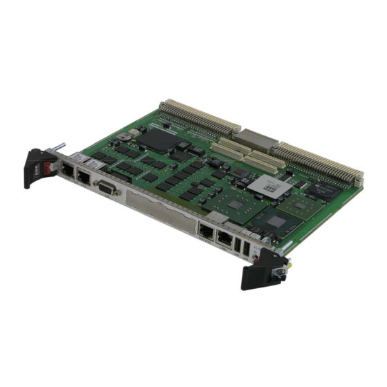
Page 44: Figure 6: Vr11 Board With Pmc Sockets
Figure 7: Front panel on single slot board Refer to the drawing for the location of interfaces on the front panel of the VP11 dual slot board: GE Intelligent Platforms – VR11, VP11 Hardware Reference Manual, Second Edition Page 44... -
Page 45: Figure 8: Front Panel On Dual Slot Board
VMEbus carrier (base board), VR11 in this case. The correlation between PMC add-on modules and routing of I/O signals from/to the VME backplane via the VR11 needs to be compliant on both ends. VMEbus Connector P1 (P7301) The following table lists the pin assignments of connector P1. -
Page 46: Table 4: Vmebus Connector P1
Rows a and c are compliant to the VMEbus specifications ANSI/VITA 1 (VME64) and ANSI/VITA 1.1 (VME64x), ANSI/VITA 35-2000 chapter 2.3 ´Mapping of Single PMC-P4 to VME-P2-Rows-A,C´. GE Intelligent Platforms – VR11, VP11 Hardware Reference Manual, Second Edition Page 46... -
Page 47: Table 5: Vmebus Connector P2
C1_..., C2_... TMDS TX… VMEbus Connector P0 (P7300) with partial PMC-I/O Note: The LAN pin assignment is compliant to the VITA 31.1 specification 'Gigabit Ethernet on VME64x Backplanes'. GE Intelligent Platforms – VR11, VP11 Hardware Reference Manual, Second Edition Page 47... -
Page 48: Table 6: Vmebus Connector P0 With Partial I/O And Hd Interface
+3.3V_SW switched-on after ramp-up. This is the only 3.3 VDC source for the Transition Module VTM22. Do not connect the +3.3V_SW pin to +3.3 V pins; damage may occur. GE Intelligent Platforms – VR11, VP11 Hardware Reference Manual, Second Edition Page 48... -
Page 49: Table 7: Vmebus Connector P0 With Partial I/O, Hd Interface, Sata, Audio
PMC I/O02, 03,07, 08, 11, 12, 13, 17, 18, 22, 23, 27, 28, 32, 49, 50, 61, 62. VMEbus Connector P0 (P7300) with full PMC-I/O Note: The LAN pin assignment is compliant to the VITA 31.1 specification 'Gigabit Ethernet on VME64x Backplanes'. GE Intelligent Platforms – VR11, VP11 Hardware Reference Manual, Second Edition Page 49... -
Page 50: Table 8: Vmebus Connector P0 With Full I/O
The IDE interface is designed as a 44-pin 2 mm pitch male onboard connector P1800 to fit directly to a 2.5-inch IDE hard drive or flash disk. P1800 is the secondary IDE interface of the onboard IDE controller. GE Intelligent Platforms – VR11, VP11 Hardware Reference Manual, Second Edition Page 50... -
Page 51: Figure 9: Ide Connector
Figure 9: IDE connector GE Intelligent Platforms – VR11, VP11 Hardware Reference Manual, Second Edition Page 51... -
Page 52: Table 9: Ide Connector
28 27 HD_RDY 30 29 \HD_DAK 32 31 HD_IRQ DIAG 34 33 HD_A1 HD_A2 36 35 HD_A0 \HD_CS1 38 37 \HD_CS0 40 39 DASP 42 41 44 43 GE Intelligent Platforms – VR11, VP11 Hardware Reference Manual, Second Edition Page 52... -
Page 53: Figure 10: Ethernet Connectors
LP_DC- RxD- LP_DB- LP_DD+ LP_DD- Two LED’s (LED1-green and LED2-yellow) are integrated in each of the RJ45 connector. These LED’s indicates the link status of the interface. GE Intelligent Platforms – VR11, VP11 Hardware Reference Manual, Second Edition Page 53... -
Page 54: Figure 12: Fast Ethernet Connector Layout
Figure 12: Fast Ethernet connector layout Serial Port COM1 (P2200) The VR11 offers two RS232 serial ports. All COM ports are accessible via the transition module; additionally COM1 (only RS232) is accessible via the front panel connector. -
Page 55: Figure 13: Com1 Location
A short cable is optionally available to convert the RJ45 style RS232 (without RI) mechanically/electrically to a Sub-D9 connector (see table below). The pin assignment for this optional cable (YLR015RS) is shown below. GE Intelligent Platforms – VR11, VP11 Hardware Reference Manual, Second Edition Page 55... -
Page 56: Figure 14: Vga Interface
RS232 Male n. a. VGA Interface (P4200) The monitor signals are available at the front panel on a standard 15-pin female D-Sub connector. Figure 14: VGA interface GE Intelligent Platforms – VR11, VP11 Hardware Reference Manual, Second Edition Page 56... -
Page 57: Figure 15: Usb
USB Interfaces (P1680, P1681) Two USB channels are available at the front panel and two USB channels are available on rear IO. Figure 15: USB Figure 16: USB pin assignment GE Intelligent Platforms – VR11, VP11 Hardware Reference Manual, Second Edition Page 57... -
Page 58: Table 15: Usb Pin Assignments
The PCI signaling voltage is fixed to 3.3 V. Nevertheless PMC cards with 3.3 V or 5 V supply voltage can be used on this PMC slot. GE Intelligent Platforms – VR11, VP11 Hardware Reference Manual, Second Edition Page 58... -
Page 59: Table 16: Pmc1 Connector Pin Assignments
Only available if connected at the VME backplane. PMC2 Connectors (P7201, P7202) PMC2 is available on a VR11 only without the front Ethernet, onboard IDE and/or front VGA connector. On a dual slot VP11, the PMC2 is available in the... -
Page 60: Table 17: Pmc2 Connector Pin Assignments
+3.3 V RES. SERR# C/BE1# V(I/O) AD14 AD15 AD13 AD12 AD11 AD10 +5 V +3.3V C/BE0# REQB# +3.3 V GNTB# Reserved V(I/O) RESETOUT# +5 V +3.3 V GE Intelligent Platforms – VR11, VP11 Hardware Reference Manual, Second Edition Page 60... -
Page 61: Pmc-I/O Connector (P6204 And P7204)
IDE-signals! Transition Module Please refer to the appendix A for interface location and connector pin assignments for the optional extension boards and transition modules. GE Intelligent Platforms – VR11, VP11 Hardware Reference Manual, Second Edition Page 61... - Page 62 GE Intelligent Platforms – VR11, VP11 Hardware Reference Manual, Second Edition Page 62...
-
Page 63: Table 18: Memory Map
Chapter Scope This chapter describes system resources, such as memory mapping, register set and default interrupt request assignments. Memory Map The table below shows the memory address area used by the VR11. Table 18: Memory map Address Size Used by... -
Page 64: Table 19: Standard Register Set
Used for onboard programmable options. They are not intended to be used from normal users. For more explanation please check the ‘Board Specific Hardware Programmer’s Manual’. Plug and Play Devices See ´Board Specific Hardware Programmer’s Manual´. GE Intelligent Platforms – VR11, VP11 Hardware Reference Manual, Second Edition Page 64... -
Page 65: Table 20: Interrupt Assignments
SETUP or when IDE is configured to 'native PCI' mode. . This interrupt is available when the secondary IDE is disabled in SETUP or when IDE is configured to 'native PCI' mode. GE Intelligent Platforms – VR11, VP11 Hardware Reference Manual, Second Edition Page 65... -
Page 66: Apic Controller
For example, interrupt 10 may be given a higher priority than interrupt 3. • More Interrupts. The three I/O APICs in the VR11 support a total of 28 independent interrupt sources. GE Intelligent Platforms – VR11, VP11 Hardware Reference Manual, Second Edition... -
Page 67: Processor
DRAM (DDR2) with a data bus width of 64 bits + ECC. One, two or four banks are provided by the VR11 with a size of either 512 MByte or 1024 MByte. This results in a minimum memory size of 512 MByte and a maximum size of 4 GByte. -
Page 68: Table 21: Interval Timer Functions
The interrupts on the IRQ input lines are handled by two registers, the interrupt request register IRR and the in-service register ISR. For programming details see the 82C59A data sheet. The VR11 support also the Interrupt handling of the APIC (Advanced Interrupt Controller). This handling of the APIC interrupt services must be supported by the operating system. -
Page 69: Real Time Clock
Using EIDE and SCSI devices: MS-DOS 6.22 can handle up to seven hard disks at a time. The VR11 products allow the simultaneous use of EIDE and SCSI hard disks. BIOS setup allows the re-ordering of the drives to boot from either SCSI or EIDE drives. -
Page 70: Table 22: Software Interfaces
• CRT resolution up to 1600x1200, DVI up to 1600x1200 Note: Termination resistors of the RGB lines are on the VR11 board for both front and rear interfaces. At higher resolutions the cable and connectors have great influence on picture quality. -
Page 71: Table 23: Additional Devices
Semiconductors. Serial EEPROM For storage of user data a serial EEPROM is implemented on the VR11 board. The user EEPROM is a 24C512 type with 64 kBytes of memory. More information about writing and reading the contents can be found in the data sheets from the manufacturer (e.g. -
Page 72: Geographic Addressing
Specific Hardware Programmer’s Manual. Watchdog, Powerfail Monitor In order to secure application software, the VR11 offers a software controlled hardware two stage counter with independent count values for each stage. First stage generates an INT or SMI. The second stage issuing a reset signal if its time-out interval expires. -
Page 73: Table 24: Bios Power Up Status
IO connector at the rear side and GND. Speaker An internal buzzer is implemented on the VR11 except on a VR11 style 8. An external standard PC compatible speaker may be connected between the appropriate IO connector at the rear side and +5 V. - Page 74 GE Intelligent Platforms – VR11, VP11 Hardware Reference Manual, Second Edition Page 74...
-
Page 76: Power Consumption
Total board size: 6U, 4 HP (VR11) Total size with optional extension board 8HP (VP11) Dimensions PCB: 233.35 mm x 178 mm x 20 mm (VR11 single Slot) PCB: 233.35 mm x 178 mm x 40 mm (VP11 dual Slot) Weight Approx. -
Page 77: Table 25: Power Consumption Cpu Dependent
When using onboard PMC modules don’t forget to add their power consumption • With an onboard hard disk drive please add the following values to the +5 V current: GE Intelligent Platforms – VR11, VP11 Hardware Reference Manual, Second Edition Page 77... -
Page 78: Figure 17: Battery Current Versus Temperature
All values were taken at 40 % RH (relative humidity). Using the values of the diagram above (Battery current versus temperature) lifetime of the battery can be derived from the diagram below (Battery current versus time). GE Intelligent Platforms – VR11, VP11 Hardware Reference Manual, Second Edition Page 78... -
Page 79: Figure 18: Battery Current Versus Time
25 °C. Self-discharge rates increase by less than 3 percent per year for temperature values up to 95 °C. The battery has a user accessible holder on the VR11. GE Intelligent Platforms – VR11, VP11 Hardware Reference Manual, Second Edition Page 79... -
Page 80: Figure 19: Battery Removal
Without an onboard battery it is recommended to use an external supply connected to this input. This voltage supplies the real time clock and the CMOS RAM for storing the BIOS Setup settings. GE Intelligent Platforms – VR11, VP11 Hardware Reference Manual, Second Edition Page 80... -
Page 81: Table 27: Environment Conditions
VP11 only supports style 1 and 3. Storage temperature on style 6 & 8 is between -55 °C (low) and +105 °C (high). Shock and vibration values for the VR11 designed to meet the values listed below: Table 28: Shock & vibration parameters... -
Page 82: Figure 20: Air Temperature Vs. Air Speed
VP11 only supports style 1 and 3 Maximum height usage for the VR11 is specified in the table below. Table 29: Maximum height usage Style 1, 3, 6 Style 8 Maximum height Operating 4.5 km Vacuum Storage 12 km Vacuum Only the style 8 board is capable to be used in a vacuum environment. -
Page 83: Table 30: Card Edge Temperatures For Style 8
The supply voltages are +5 V and 3.3 V. +12 V and -12 V are required only if needed on the PMC slot. All Output voltages of the VR11 boards have an over- current protection. The maximum current for each voltage is shown below:... -
Page 84: Table 32: Supply Voltage Range
GND and any other supply voltage. By itself the onboard digital ground GND and the front panel/chassis frame ground FGND are isolated on the VR11 with a layout distance of more than 0.3 mm in all PCB layers. However, most standard devices (keyboard, mouse, and monitor) except Ethernet will connect FGND and GND directly in the device. -
Page 85: Board Layout Drawings
Board layouts change occasionally. Please check for correct revision of layout drawings. They are inserted here in ascending order if there is more than one version. In case of doubt consult GE Intelligent Platforms. GE Intelligent Platforms – VR11, VP11 Hardware Reference Manual, Second Edition Page 85... -
Page 86: Figure 21: Component Side Of Vr11 (V0)
Placement Plan Component Side VR11 (V0) Figure 21: Component side of VR11 (V0) GE Intelligent Platforms – VR11, VP11 Hardware Reference Manual, Second Edition Page 86... -
Page 87: Figure 22: Bottom Side Of Vr11 (V0)
Placement Plan Bottom Side VR11 (V0) Figure 22: Bottom side of VR11 (V0) GE Intelligent Platforms – VR11, VP11 Hardware Reference Manual, Second Edition Page 87... -
Page 88: Figure 23: Component Side Of Vr11 (V1)
Placement Plan Component Side VR11 (V1) Figure 23: Component side of VR11 (V1) GE Intelligent Platforms – VR11, VP11 Hardware Reference Manual, Second Edition Page 88... -
Page 89: Figure 24: Bottom Side Of Vr11 (V0)
Placement Plan Bottom Side VR11 (V1) Figure 24: Bottom side of VR11 (V0) GE Intelligent Platforms – VR11, VP11 Hardware Reference Manual, Second Edition Page 89... - Page 90 GE Intelligent Platforms – VR11, VP11 Hardware Reference Manual, Second Edition Page 90...
- Page 91 DVI-to-VGA adaptor connected to P4100. You never can use two display devices connected to the transition module. If you want to have two display outputs, you will have to connect one to the front of the VR11 and one to the rear transition module.
-
Page 92: Figure 25: Vtm22 Transition Module
Figure 25: VTM22 Transition Module GE Intelligent Platforms – VR11, VP11 Hardware Reference Manual, Second Edition Page 92... -
Page 93: Table 35: Vtm22 Ide Connector
HD_IRQ HD_A1 HD_A2 HD_A0 \HD_CS3 \HD_CS1 Ethernet Interface 10/100/1000BaseT (P5000, P5500) The Ethernet interfaces for RearI/O requires usage of CAT 5 cable for proper operation with 100/1000BaseT. GE Intelligent Platforms – VR11, VP11 Hardware Reference Manual, Second Edition Page 93... -
Page 94: Figure 26: Ethernet Connector Pin Assignment
These LED’s indicate the link status of the interface. Table 37: VTM22 LEDs LED1 green Function Link No link LED2 yellow Function On, blink Tx/Rx activity No activity GE Intelligent Platforms – VR11, VP11 Hardware Reference Manual, Second Edition Page 94... -
Page 95: Table 38: Vtm22 Tmds Connector
Serial Interfaces COM1 (P2200, P2100) and COM2 (P2201, P2203) The VR11 offers two RS232 serial ports. All COM ports are accessible via the transition module at 10 pole headers and are software selectable for RS-232 or RS-422/485 operation. -
Page 96: Table 39: Vtm22 Com1
P4100, or a standard VGA Monitor/Display connected to P4001, or a standard VGA Monitor/Display via a DVI-to-VGA adaptor connected to P4100. You never can use two display devices connected to the transition module. If you GE Intelligent Platforms – VR11, VP11 Hardware Reference Manual, Second Edition Page 96... -
Page 97: Figure 27: Dvi-I Connector Layout
Both digital and analog video signals are provided. For the digital signals the 'Transition Minimized Differential Signaling' (TMDS) is used. The maximum resolution with a VR11 is limited to 1024x768. Figure 27: DVI-I connector layout GE Intelligent Platforms – VR11, VP11 Hardware Reference Manual, Second Edition Page 97... -
Page 98: Table 42: Vtm22 Dvi-I Connector Digital Pin Assignments
USB connectors (P1600, P1601) Two channels are available at the standard USB connectors. FUSE_VCC is fused with 2 A, but for normal operation don’t exceed 1 A at this pin. GE Intelligent Platforms – VR11, VP11 Hardware Reference Manual, Second Edition Page 98... -
Page 99: Table 44: Vtm22 Usb0
Miscellaneous connector (P2000) Table 46: VTM22 Miscellaneous Connector Name P2000 Name \M1LINK \M1ACT \M2LINK \M2ACT \RST_BUT FUSE_VCC \SPEAKER FUSE_VCC FUSE_VCC \STATUS_LED FUSE_VCC FUSE_VCC FUSE_VCC USB1- USB1+ USB0- USB0+ GE Intelligent Platforms – VR11, VP11 Hardware Reference Manual, Second Edition Page 99... -
Page 100: Table 47: Pmc I/O Connectors
PMCx_IO44 PMCx_IO45 PMCx_IO46 PMCx_IO47 PMCx_IO48 PMCx_IO49 PMCx_IO50 PMCx_IO51 PMCx_IO52 +5 V PMCx_IO53 PMCx_IO54 PMCx_IO55 PMCx_IO56 PMCx_IO57 +3.3 V PMCx_IO58 PMCx_IO59 PMCx_IO60 -12 V PMCx_IO61 PMCx_IO62 PMCx_IO63 PMCx_IO64 GE Intelligent Platforms – VR11, VP11 Hardware Reference Manual, Second Edition Page 100... -
Page 101: Table 48: Pmc I/O Header
51 52 PMCx_IO52 PMCx_IO53 53 54 PMCx_IO54 PMCx_IO55 55 56 PMCx_IO56 PMCx_IO57 57 58 PMCx_IO58 PMCx_IO59 59 60 PMCx_IO60 PMCx_IO61 61 62 PMCx_IO62 PMCx_IO63 63 64 PMCx_IO64 GE Intelligent Platforms – VR11, VP11 Hardware Reference Manual, Second Edition Page 101... -
Page 102: Table 49: Vtm22 Vga 2
Table 50: VTM22 SATA 0 P1700 Name SATATX0 \SATATX0 \SATARX0 SATARX0 1, 4, 7 Table 51: VTM22 SATA 1 P1701 Name SATATX1 \SATATX1 \SATARX1 SATARX1 1, 4, 7 GE Intelligent Platforms – VR11, VP11 Hardware Reference Manual, Second Edition Page 102... -
Page 103: Table 52: Vtm22 Sata Hd Direct
Left and right channels are opposite to standard. The above pin assignment represents the actual configuration on the VTM22. SPDIF connector Table 54: VTM22 SPDIF P2901 Name SPDIF out VCC3 4, 5 GE Intelligent Platforms – VR11, VP11 Hardware Reference Manual, Second Edition Page 103... -
Page 104: Table 55: Vtm22 Audio
Line in left Line in right 1, 3, 4 Note: Left and right channels are opposite to standard. The above pin assignment represents the actual configuration on the VTM22. GE Intelligent Platforms – VR11, VP11 Hardware Reference Manual, Second Edition Page 104... -
Page 105: Figure 28: Placement Plan Vtm22, V0
Placement Plan VTM22V0 Figure 28: Placement plan VTM22, V0 GE Intelligent Platforms – VR11, VP11 Hardware Reference Manual, Second Edition Page 105... - Page 106 GE Intelligent Platforms – VR11, VP11 Hardware Reference Manual, Second Edition Page 106...
-
Page 107: Table 58: Electrical Characteristics
PMC Slot1 is 66/100/133 MHz PCI-X capable. PMC Slot 2 is 33 MHz/32 bit only. The user definable I/O Pins are connected to the rear IO connector on the VR11, as defined in the VITA 36 specification. • A 5 V key is mounted on PMC2, for 5 V compatible PMC cards. -
Page 108: Figure 29: Mounting Of Pmc Module On Vr11
Mounting of PMC module To mount a PMC board to the VR11, follow these steps: 1. Remove VR11 from system housing 2. Remove the front panel cover of the PMC slot 3. Take PMC from inside through front panel and push connectors together. -
Page 109: Figure 30: Mounting Of Secondary Thermal Interface On Pmc Module
On conduction-cooled versions of boards and mezzanines the PMC modules may be equipped with optional Secondary Thermal Interfaces. If the PMCs do not fit into their sockets on the VR11 base board then you can remove them. Use a matching TORX screw driver to remove the Secodary Thermal Interfaces. - Page 110 GE Intelligent Platforms – VR11, VP11 Hardware Reference Manual, Second Edition Page 110...
-
Page 111: Basic Compatibility
The Vx11 offers a second USB port on the front panel instead of the removed PS/2 connectors. The serial port connector is a RJ45 type on the Vx11. The Vx11 has an optional Fast Ethernet port on its front panel. GE Intelligent Platforms – VR11, VP11 Hardware Reference Manual, Second Edition Page 111... -
Page 112: Table 59: Rear I/O Pin Assignments For Vx9 & Vx11
√ √ √ √ √ √ COM2 √ √ √ √ √ √ PMC 1 I/O √ √ √ √ √ √ VME bus √ √ √ GE Intelligent Platforms – VR11, VP11 Hardware Reference Manual, Second Edition Page 112... - Page 113 PMC 2 rear I/O is not possible if Ethernet 1 & 2 or VGA on the front are used because the PMC cannot installed on the SBC in this case Note: If onboard hard disk/flash drive is used than no PMC 2 is available GE Intelligent Platforms – VR11, VP11 Hardware Reference Manual, Second Edition Page 113...
- Page 114 GE Intelligent Platforms – VR11, VP11 Hardware Reference Manual, Second Edition Page 114...
-
Page 115: Technical Support
AUS, NZ) Technical Support If you should have a problem with a GE Intelligent Platforms product: Free technical support is available by phone, fax or email. Telephone support is available at main locations or at the regional center where the product was bought. -
Page 116: Error Report
In case of difficulties provide at least the information listed below to an appropriate support center or on their web site as listed above: GE Intelligent Platforms – VR11, VP11 Hardware Reference Manual, Second Edition Page 116... - Page 117 • RMA Number, if applicable • Product & Serial Number • Part Number • Version • Contact: Name & Phone Number • Detailed Description of the Problem/Defect GE Intelligent Platforms – VR11, VP11 Hardware Reference Manual, Second Edition Page 117...
-
Page 118: Additional Resources
Additional Resources © 2010 GE Intelligent Platforms Embedded Systems, Inc. All rights reserved. Information Centers * indicates a trademark of GE Intelligent For more information, please visit Platforms, Inc. and/or its affiliates. All other the GE Intelligent Platforms Embedded Sys-...