Table of Contents
Advertisement
Advertisement
Table of Contents

Related Manuals for Sharp JH-1600E

Summary of Contents for Sharp JH-1600E
- Page 1 SOLAR POWER CONDITIONER Service Manual...
-
Page 2: Table Of Contents
JH-1600E Released in May 2009 Version: V00 TABLE OF CONTENTS Important Service Safety Precautions…………………………………………… Warning…………………………………………………………………………….. General Information……………………………………………………………….. 1 System Overview ..........................2 Overview of Solar Power Conditioner ................3 Solar Power Conditioner Specifications................Analyzing Defect Situation………………………………………………………… 1 Analyzing Defect Situation.................... -
Page 3: Important Service Safety Precautions
Important Service Safety Precautions This manual contains important safety instructions for JH-16000 E that shall be followed during the installation of the solar power conditioner. To reduce the risk of electrical shock, and to ensure the safe installation and operation of the solar power conditioner, the following words appear throughout this manual to inform you or alert you something may cause dangerous situation or safety instructions must be followed. -
Page 4: Warning
WARNING These servicing instructions are for user by qualified personnel only. To reduce the risk of electrical shock, do not perform any servicing other than that specified in the operating instructions unless you are qualified to do so. Be sure to use appropriate service parts listed in the replacement parts list and tools when you repair the solar power conditioner. - Page 5 Cables should not be damaged or assembled. Do not use cables or lead wires with scar or deteriorated ones. Replace them with appropriate one immediately. Otherwise, it may cause an electrical shock or fire. Be sure to confirm the location applied for a part, wiring, soldering or the connection status of crimping terminal, are all appropriate.
-
Page 6: General Information
General Information 1. System overview Item Function Description Remark PV module Convert solar energy to electric power PV: photovoltaic Mounting Fix the PV module on the roof with mounting structure structure. DC Wiring Connect PV array to DC breaker PV array: A number of cable PV modules connected together in... -
Page 7: Overview Of Solar Power Conditioner
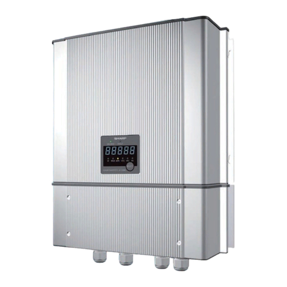
2. Overview of solar power conditioner Unit: mm Fig1. Dimension of solar power conditioner... - Page 8 Unit: mm Fig2. Dimension of bracket Fig3. Terminal of solar power conditioner...
- Page 9 Table1. Mechanical specification JH-1600E Outdoor enclosure Main body IP65 Wiring box IP55 Dimensions - without wall mount 440*348*141 mm (H*W*D / mm) Dimensions - with wall mount 440*348*153 mm (H*W*D / mm) Shipping dimension (H*W*D / mm) 515*450*290 mm Inverter weight...
-
Page 10: Solar Power Conditioner Specifications
3. Solar power conditioner specifications Model JH-1600E Maximum system voltage 350 V Rating input voltage (DC) 240 V Range of operating DC voltage(DC) 60~320 V Maximum array short circuit current(DC) 10A Maximum operating current(DC) 8.5A Nominal output voltage(AC) 230 V Operating voltage range(AC) 210 –... -
Page 11: Analyzing Defect Situation
Analyzing Defect Situation 1. Analyzing Defect Situation I. Checking serial number Check and record the serial number of the solar power conditioner (You can find it in the rating label located at right side of the unit). Representation of serial number: A. - Page 12 Installing the conditioner in the place mentioned above may cause the malfunction of the system caused by water or high temperature inside the solar power conditioner. III. Checking accumulated power Check whether the solar power conditioner is in either of the following conditions. The solar power conditioner is powered on (Indicator is displayed on the solar power conditioner display).
-
Page 13: Checking Pv Power System Flow Chart
2. Checking PV Power System Flow Chart Before checking the solar power conditioner, confirm that the following setting and connections of the PV power system: 1. DC disconnect 2. PV string 3. AC disconnect 4. Utility grid Check PV system Check DC disconnect device Connection Repair DC disconnect... -
Page 14: Checking And Changing Parameter Of Operating Condition
3. Checking and Changing Parameter of Operating Condition Purpose: If need to adjust the parameter (voltage / frequency protection level, disconnecting / reconnecting time setting, product ID) of solar power conditioner to meet the local application, follow below procedures to check and change parameters of solar power conditioner. 1. - Page 15 Setting parameter flow chart Please refer to the Push 'ENT' for 5 seconds Error/Fault code MPPT mode Error List Fault mode Night time mode Standby mode Day Power List Changed Parameters Setting Please refer to the software Setting ● ● ●...
- Page 16 List of Parameters for Operating Condition Function explanation: Utility over voltage (Vac): Setting utility over voltage trigger value. Utility under voltage (Vac): Setting utility under voltage trigger value. Voltage abnormal trip time (sec): Setting trip time when over and under voltage protection is triggered.
-
Page 17: Clearing Error
4. Clearing Error 4.1 Clearing error code list inside the unit Step1: Press ENT button for 5 seconds. “OFF” is displayed. Step2: Press SEL button the display panel show “EL”. Step3: Press SEL button the display panel show “dAY-P”. Step4: Press SEL button the display panel show “PS”. Step5: Press SEL button the display panel show “d-rSL”. -
Page 18: Error Code And Service
5. Error Code and Service Recovery method explanation: Recovery method A: Auto-restart after default reconnecting time. Recovery method B: Auto-restart after waiting 10 sec. III. Recovery method C: Auto-restart after waiting 10 sec. But enter recovery method D when error four times (show d-XX error code.) IV. - Page 19 Check The solar power conditioner is in normal status. Wait until the utility grid recovers. The solar power conditioner will restart Action automatically. Cause AC breaker is shut down. Check Check the status of the AC breaker. Case.2 Turn on the AC beaker. The utility grid is received and the solar power Action conditioner will restart automatically.
- Page 20 Check If the error message “F-02” appears frequently after restarting the solar power conditioner, the frequency detecting circuit on the control circuit is in abnormal condition. Action Replace a new solar power conditioner. Error code Recovery method : A F-03 Description Utility frequency under setting value Protection level Less 47Hz [Parametr:46Hz / 47Hz / 48Hz]...
- Page 21 Protection level --- Activation time Case.1 Cause Power failure of the utility grid. Check The solar power conditioner is in normal status. Action Wait until the utility grid recovers. The solar power conditioner will restart automatically. Case.2 Cause The solar power conditioner stops unnecessary. Check Confirm that the solar power conditioner restarts, and check the status when F-07 occurs.
- Page 22 Error code Recovery method : B P-11 Description PV array over voltage Protection level More than 320V Activation time 200 mS Case.1 Cause Input voltage of the solar power conditioner exceeds the limited value. Check Check the voltage of all input terminal of the solar power conditioner. Action (1) If the input voltage is large than 350V.
- Page 23 Error code Recovery method : C E-16 (d-16) Description Communication error. Protection level --- Activation time Case.1 Cause Noise interference Check Confirm that the AC and PV terminal noise. If the noise is large beyond acceptable. Turn off solar power conditioner immediately. Restart solar power conditioner after noise is disappearance.
- Page 24 Action Replace a new solar power conditioner. Error code Recovery method : B E-18 Description Ground fault. Protection level --- Activation time Case.1 Cause PV array grounding fail. Check Confirm PV array resistance between the PV + / - and GND. If the resistance is lower 640Kohm, ask dealer to check PV array.
- Page 25 Activation time 300ms Case.1 Cause Bad utility waveform Check Check the waveform of the utility. Action Avoid the interference on the utility waveform. Case.2 Cause Defect of the solar power conditioner. Check If the error message “E-21” appears frequently after restart the solar power conditioner, the solar power conditioner is in abnormal condition.
- Page 26 Activation time Case.1 Cause Ambient over spec. Check Measure the ambient, if over 60C than solar power conditioner stops. Action Waiting for ambient decrease. Case.2 Cause The solar power conditioner is located in inappropriate location. Check Obstruction around the solar power conditioner may cover the enclosure of solar power conditioner for admission/evacuation.
- Page 27 Error code Recovery method : C E-27(D-27) Description Relay open Protection level Activation time Case.1 Cause Relay is damage. Check If the error message “E-27” appears frequently after restart the solar power conditioner, the solar power conditioner is in abnormal condition. If this error occurs four times successively, “d-27”...
- Page 28 Description EEPROM abnormal. Protection level -- Activation time Case.1 Cause EEPROM failed. Check If the error message “D-40” appears frequently after confirming the PV array voltage. The solar power conditioner is damaged. Action Replace a new display board.
-
Page 29: Replacing Fuse
Replacing Fuse 1. Detaching Wiring Box If you have to detaching wiring box, be sure to turn off AC and DC input breaker for the solar power conditioner in advance. Otherwise, it may cause an electrical shock. Confirm the DC and AC power are turned off, and remove four screws located on the wiring box cover and take off the wiring box cover. -
Page 30: Replacing Ac Or Dc Fuse
4. Replacing AC or DC Fuse Perform “1. Detaching Wiring Box”, and remove the wiring box cover of the conditioner. Remove the AC fuse from the holder. III. Remove the DC fuse from the holder. IV. Insert a new AC fuse (FUW2) into the holder. (little fuse : 20A/250V) Insert a new DC fuse (FUW1) into the holder. -
Page 31: Replacing Unit
Replacing Unit 1. Detaching Wiring Box If you have to detaching wiring box, be sure to turn off AC and DC input breaker for the solar power conditioner in advance. Otherwise, it may cause an electrical shock. Confirm the DC and AC power are turned off, and remove four screws located on the wiring box cover and take off the wiring box cover. -
Page 32: Remove The Unit From The Wall Mount Bracket
4. Remove the unit from the wall mount bracket... -
Page 33: Checking System Condition After Service
Checking System Condition after Service 1. Checking DC input Confirm that DC and AC power breaker are turned off. If they are turned on, turn off them. Remove the wiring box cover of the solar power conditioner. III. Measure the voltage of PV string on the input side of the DC breaker. If the PV voltage is more than 70V, turn on the DC breaker. -
Page 34: Circuit And Electrical Block Diagram
Circuit and electrical block diagram Item Function Description DC EMI To prevent conduction noise out from DC cable. Boost To regular DC voltage for inverter stage. Full bridge Using four MOSFETs as switch to inverter DC voltage to AC voltage. Driver board Generator driver signal of full bridge for MOSFETs. -
Page 35: Replacement Parts List
Replacement Parts List Item Parts Code Description Quantity 9NK0813221802 AC fuse 9NK0891040102 DC fuse 9NK3071538194 Terminal block(DC) 9NK3071539594 Terminal block(AC) 9NK3262043000 Shock Hazard warning label 9NK3470343100 AC/DC Gland 9NK3470343200 RJ45 Gland 9NK3312387700 Wiring box front cover 9NK3263048200 Label for wiring box front cover (upper side) - Page 36 Item Parts Code Description Quantity (10) 9NK3103381000 Screw for wiring box front cover (11) 9NK3105299000 Screw for main body (12) 9NK3263876000 Rating label (13) 9NK3262043100 Burn Hazard warning label...
- Page 37 Item Parts Code Description Quantity (101) 9NK35136666XX Carton 511*445*295mm (102) 9NK35188380XX Bottom end block EPE (103) 9NK35009554XX Bag PE (104) 9NK35188379XX Top end block EPE Item Parts Code Description Quantity (105) 9NK33123936XX Wall mounting bracket (106) 9NK31033810XX Screw M#6-32*10 (Fix unit to the bracket) (107) 9NK31090374XX Screw ψ5.5*1.8*80 (Fix bracket to the wall) (108)
-
Page 38: Packing Instruction
Packing instruction...