Table of Contents
Advertisement
Advertisement
Chapters
Table of Contents

Related Manuals for Panasonic AG-CPD15P


Summary of Contents for Panasonic AG-CPD15P
-
Page 1: Operating Instructions
Operating Instructions Memory Card Video Recorder AG-CPD15P Model No. Car Use only Toughbook Arbitrator Before operating this product, please read the instructions carefully and save this manual for future use. ENGLISH S0806K8088 -M Printed in Japan VQT1A18-7... -
Page 2: Read This First
Read this first! WARNING: • TO REDUCE THE RISK OF FIRE OR SHOCK HAZARD, DO NOT EXPOSE THIS EQUIPMENT TO RAIN OR MOISTURE. • TO REDUCE THE RISK OF FIRE OR SHOCK HAZARD, KEEP THIS EQUIPMENT AWAY FROM ALL LIQUIDS. USE AND STORE ONLY IN LOCATIONS WHICH ARE NOT EXPOSED TO THE RISK OF DRIPPING OR SPLASHING LIQUIDS, AND DO NOT PLACE ANY LIQUID CONTAINERS ON TOP OF THE EQUIPMENT. - Page 3 Read this first! (continued) CAUTION: In order to maintain adequate ventilation, do not install or place this unit in a book case, built-in cabinet or any other confined space. To prevent risk of electric shock or fire hazard due to overheating, ensure that curtains and any other materials do not obstruct the ventilation.
-
Page 4: Important Safety Instructions
IMPORTANT SAFETY INSTRUCTIONS (1) Read these instructions. (2) Keep these instructions. (3) Heed all warnings. (4) Follow all instructions. (5) Do not use this equipment near water. (6) Clean only with a dry cloth. (7) Do not block any ventilation openings. Install in accordance with the manufacturer’s instructions. -
Page 5: Table Of Contents
Contents Read this first! ........2 IMPORTANT SAFETY INSTRUCTIONS ..4 Before use Features ..........7 Before Use ........9 Included Accessories .......8 Notes on Handling ......10 Options ..........8 Control Reference Guide ....11 About This Manual ......8 Connections ........15 Operation on the Memory Card Video Recorder P2 card Insertion and Removal ..17 About the Internal Clock ....19 Inserting a P2 card .......17... -
Page 6: Administrator Setup
Details on GPL and LGPL can be found in the GPL and LGPL sections of this manual. To obtain the source codes, go to the following home page. https://eww.pavc.panasonic.co.jp/pro-av/ The manufacturer asks users to refrain from directing inquiries concerning the source codes they have obtained and other details to its representatives. -
Page 7: Features
Features Record video on memory cards Video and audio files can be recorded on memory cards with the “P2” logo (such as the separately sold AJ-P2C016RG afterwards called P2 cards), in MPEG4 and G.726 formats. Record a variety of information In addition to video and audio files, meta information including recording date and time and recording triggers... -
Page 8: Included Accessories
Included Accessories Key ............1 Mounting bracket (attached to the recorder) ....2 Options P2 card Color Camera (AG-CK10P) 16 GB (AJ-P2C016RG) 32 GB (AJ-P2C032RG) Cable Kit (AG-CR12P) Remote Control Panel (AG-RCP30P) About This Manual This manual is organized as described “Menu Screen of the Remote b e l o w a n d u s e s t h e f o l l o w i n g Control Panel (separately sold)”... -
Page 9: Before Use
“Format” on page 86 or contact your supplier. In no event will Panasonic be liable for any damages, including any incidental • or consequential damages, stemming from a failure to record data or from lost settings or data. -
Page 10: Notes On Handling
Notes on Handling Usage Precautions for use of P2 cards • Do not remove a P2 card while (16 GB or higher capacity) it is being accessed, as the P2 • Use this unit to format new P2 cards. card may be damaged or the P2 (see “Format”... -
Page 11: Control Reference Guide
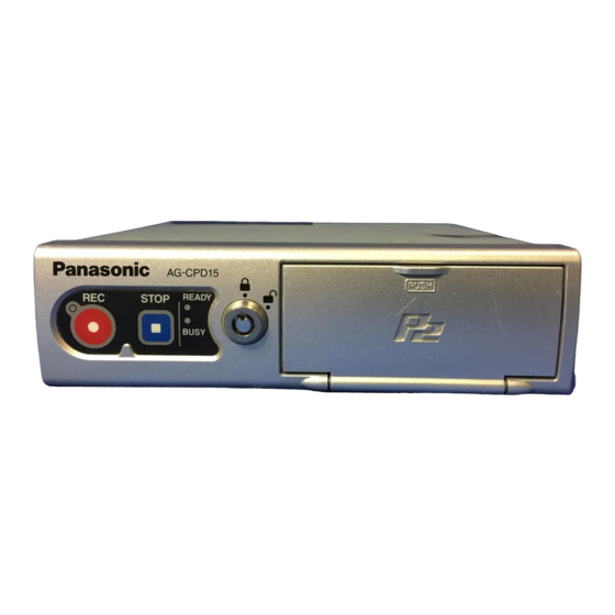
Control Reference Guide Front panel REC button ( ) READY lamp Starts recording of video and sound Lights up when recording is possible to a P2 card. on a P2 card inserted in a P2 card slot (see “Indicator Lamps and Recorder Status”... - Page 12 Control Reference Guide (continued) Rear panel (1) AUDIO OUT VIDEO OUT IN CAR MIC GPS-ANT. (OPTION) CONTROL PANEL AUDIO IN CAMERA 2 GPIO/SERIAL CAMERA 1 IN CAR MIC connector VIDEO OUT connector (Pin jack) (Pin jack) This is a mic level signal input. This is a composite signal output.
-
Page 13: Lan Connector
Control Reference Guide (continued) Rear panel (2) AUDIO OUT VIDEO OUT IN CAR MIC GPS-ANT. (OPTION) CONTROL PANEL AUDIO IN CAMERA 2 GPIO/SERIAL CAMERA 1 • Consult your supplier for help with GPS-ANT. (OPTION) connector connection. Insert the cable from the GPS antenna (included in the separately GPIO/SERIAL connector sold Cable Kit). - Page 14 Control Reference Guide (continued) Mounting bracket <Unit : mm> 187.4 (7-3/8 inches) Front Trunk mounting holes (ø3.2) Spaces for center console mounting holes These holes are used to mount the recorder in the trunk. Consult your In these spaces the holes can be supplier and request help with made to mount the recorder on the installation.
-
Page 15: Connections
Connections • Be sure to consult your supplier and request installation and connection. • Connect the red (BATT) and white (SIGNAL) wires of the power cable via a fuse (5 A). (The power cable is included in the separately sold Cable Kit.) •... - Page 16 Connections (continued) PC (commercially USB memory device available) (commercially available) Audio input LAN cable (cross (mic level) cable, commercially available) GPS antenna Remote Control Panel USB Extension (included in the (separately sold) Cable (included separately sold in the separately Cable Kit) sold Cable Kit) AUDIO OUT VIDEO OUT...
-
Page 17: P2 Card Insertion And Removal
P2 card Insertion and Removal Do not insert or remove a P2 card when another P2 card is being accessed (while the [BUSY] lamp is lit or blinking). Otherwise the P2 card may be damaged or P2 card data may be corrupted. (2) Insert a P2 card into the P2 Inserting a P2 card card slot and push it in until... -
Page 18: Removing A P2 Card
P2 card Insertion and Removal (continued) (4) Close the P2 card slot cover. Removing a P2 card Return the P2 card slot cover to its (1) Open the P2 card slot cover original closed position and press the section marked PUSH . (see previous page). -
Page 19: Turning The Recorder On And Off
Turning the Recorder On and Off Recorder power is supplied from the vehicle’s battery. Turn the vehicle’s ignition switch to ON or ACC. Power to the recorder is turned on. If the Remote Control Panel is connected, its power is also turned Turn the vehicle’s ignition switch to LOCK (OFF). -
Page 20: About The Trigger Signals
About the Trigger Signals Level signals Trigger signals (GPIO1 - 8), which are used for recording control and Color The high-level and low-level of a level Camera control, consist of edge and signal can be specified and recording level signals. control occurs when a change is detected in the specified signal. -
Page 21: Starting And Stopping Recording
Starting and Stopping Recording Select from the following detection Recording methods according to the intended Recording Start Methods application or installation conditions. Detection of own vehicle speed: • Press the [REC] button (the REC Uses the vehicle speed pulse buttons on the recorder, Color (see “Speedpulse”... -
Page 22: Stopping Recording
Starting and Stopping Recording (continued) • Video input at the [CAMERA1] - When, on a single day, the or [CAMERA2] connector (see maximum number of files that “Setup” on page 34, “Selecting can be recorded on a 16 GB a camera” on page 55 and “Init or higher capacity P2 card has Camera Select”... - Page 23 Starting and Stopping Recording (continued) Notes: Recording Stop Criteria • Continuous video and audio from Level Stop Criteria to Stop starting to stopping recording, Signal Timer Recording (whichever and including prerecording and Setting happened earlier) postrecording periods, are recorded [ S T O P ] b u t t o n i s as one file on the P2 card.
-
Page 24: On Recording
On Recording Write-protect switch Prerecording and postrecording The P2 card is equipped with a write- Prerecording is the capability of protect switch. Sliding this switch to the including material from an interval PROTECT position prevents writing before the specified start point in a data, formatting P2 cards and deleting recording. -
Page 25: Selecting The Video Source To Record
On Recording (continued) In the cases shown below, the actual Selecting the video source to record prerecord and postrecord time may be shorter than the respective setting. You can select and record video input at the [CAMERA1] or [CAMERA2] If recording is started immediately connector on the rear panel of the after system startup recorder. -
Page 26: Audio Sources When Recording
On Recording (continued) Audio sources when recording The Memory Card Video Recorder can record up to two audio channels (Audio1 and Audio2). Out of the three audio input connectors on the rear panel ([AUDIO IN 1, 2], and [IN CAR MIC]), the signal of the source connected to the [AUDIO IN 1] connector will always be recorded on the Audio1. -
Page 27: Intermittent Recording
On Recording (continued) Intermittent recording Intermittent recording records only one image per second extending recording time. Entering a recording trigger during intermittent recording interrupts intermittent recording and starts normal recording. Normal recording includes prerecording so intermittent recording and prerecording of normal recording may overlap during prerecording. -
Page 28: Programmed Recording
On Recording (continued) Programmed recording Programmed recording is a function that allows you to set recording to start and stop every day or on a specified day of the week. Programmed recording starts and stops recording according to intermittent recording setting. For example, when intermittent recording is set to “ON”, intermittent recording starts at the set start time. - Page 29 On Recording (continued) • If a recording trigger is set when intermittent recording is set to “OFF” and programmed recording is set to “ON”, only normal recording occurs and the file is not split. When a recording stop Programmed Programmed criteria other than the recording start time recording stop time...
-
Page 30: C Hanges In Intermittent Recording And Programmed Recording Status
On Recording (continued) Changes in Intermittent recording and Programmed Recording Status Status changes caused by button operations, recording triggers, recording stop criteria and other inputs are shown below for set intermittent recording and programmed recording conditions. <When intermittent recording is set to “ON”> Input Status prior When a recording stop... -
Page 31: Location And Name Of Recording Files
On Recording (continued) Location and Name of Recording Files The names of folders storing recording files are created according to the Rule of Filename. WT (world time) : “/DATA” is the base folder LT (local time) : “/DATA /LOCAL” is the base folder A folder indicating the recording start date is created in the above base folder and a file indicating the recording start time is created in that folder. -
Page 32: Location And Name Of Recording Files 31 Recording Error Warnings
On Recording (continued) Recording Error Warnings When the recorder detects that it cannot properly record audio or video, it will output the warning signals described below via GPIO9 (25-pin [GPIO/SERIAL] connector). Data output via GPIO9 Item When an error During When not recording ∗... -
Page 33: License Plate Recognition (Lpr) Mode
License Plate Recognition (LPR) Mode Engaging the License Plate Recognition (LPR) mode allows you to start up the LPR system. Set the color camera shutter speed to [LPR Shutter Speed] (1/500 or 1/1000) when using the LPR system. When a recording trigger starts a recording during license plate recognition, however, the shutter speed automatically switches to the setting configured for [Patrol Shutter Speed]. -
Page 34: Setup
Setup Factory default values are shown below. Use the Remote Control Panel to change settings. When running a PC application, the set value may be altered, or the items that can be set may be restricted. Items officers can set: Setting Item Factory Default Value Description 1 Camera... - Page 35 Setup (continued) Items administrators can set: Setting Item Factory Default Value Description 1 Rec/Play Recording and Playback Settings ∗ PowerOff Time Time from the SIGNAL turn-off to recorder shut-down (minutes) Setting : 0, 10, 20, 30, 60, 90, 120, 180, ∗...
- Page 36 Setup (continued) Setting Item Factory Default Value Description 1 Rec Continue CONTINUE Continuous recording time (minutes) Time Setting : 1, 2, 5, 10, 15, 20, 30, 60, 90, CONTINUE PreRec Time Video Prerecord time (seconds) (Video) Setting : 0, 10, 20, 30, 60, 90 PreRec Time Audio Prerecord time (seconds) (Audio)
- Page 37 Setup (continued) Setting Item Factory Default Value Description 3 Date/Time Date, Time and Time Zone Settings TimeZone Eastern Time zone Standard Hawaii Standard Time, Daylight Yukon Standard (Daylight Saving) Time, Saving Pacific Standard (Daylight Saving) Time, Time Mountain Standard (Daylight Saving) Time, Central Standard (Daylight Saving) Time, Eastern Standard (Daylight Saving) Time, Atlantic Standard (Daylight Saving) Time,...
- Page 38 Setup (continued) Setting Item Factory Default Value Description Detection Method for trigger signal (GPIO1-8) detection. Choice of signal detection depends on set [Action]. • In REC, CAM1REC and CAM2REC modes Setting : H (high-edge trigger), Level H (high-level trigger), (low-edge trigger), Level L (low-level trigger), (both-edge trigger) •...
- Page 39 Setup (continued) Setting Item Factory Default Value Description 6 Camera Color Camera setting Zoom Limit Maximum zoom magnification Setting : 22, 220 AGC Level HIGH Color Camera automatic gain control setting Setting : LOW, MID, HIGH, OFF Init Backlight Initial backlighting compensation setting (upon power on) ∗...
- Page 40 Setup (continued) Setting Item Factory Default Value Description 6 AUTO FOCUS PRESET Select color camera focusing method when, • [Init LPR Mode] is set to “DISABLE” • [Init LPR Mode] is set to “ENABLE” and [LPR Mode] is set to “PATROL” •...
- Page 41 Setup (continued) Setting Item Factory Default Value Description 7 Management Officer management setup Mode Setting Method AUTO Officer registration procedure Setting : AUTO, MANUAL, LIST Operation Key Lock of buttons by an administrator Lock Setting : ON, OFF 8 Radar/GPS Radar Gun, GPS and Speed Settings ∗...
- Page 42 Setup (continued) Setting Item Factory Default Value Description 9 Auto Auto maintenance interval and date setting Maintenance Operation Auto maintenance operation setting Setting : ON, OFF Interval Interval setting (months) Setting : 1, 3, 6, 12 Day (week) Week setting Setting : 1st, 2nd, 3rd, Last Day of the week setting (day of the week)
-
Page 43: Text Files Used With The Recorder
Text Files Used with the Recorder The following types of text files can be used by the recorder, and created with a commercially available text editor. To display correctly, the files must meet the following specifications. Refer to “Sample Files” on pages 45, 46 for examples. File Types File Types Contents... - Page 44 Text Files Used with the Recorder (continued) File Specifications Syntax: Officer data files may contain no more than one statement per line. Multiple statements or definitions on one line are invalid. Line Feed Codes: Line feeds are coded as the hexadecimal values 0Dh 0Ah or just 0Ah. Blank Lines: Blank lines are ignored.
- Page 45 If an identifier is multiply defined on different lines, the last definition line has priority. Sample Files Officer data file: FirstName=John #MiddleName= LastName=Smith ID=ICV12345 Password=panasonic SDate=2005-09-12 STime=08:15 #EDate=2005-09-12 #ETime=20:00 Shift=Patrol Area=WEST Source=Car123 # Structure of officer information file # Identifier Max.
- Page 46 FirstName=Jane MiddleName= LastName=White ID=ICV12346 Administrator Registration File : # Mike Brown FirstName=Mike MiddleName= LastName=Brown ID=ICV12347 Password=panasonic Event Type File : EvType1=FOOTBALL EvType2=BASEBALL EvType3=HOCKEY EvType6=TENNIS EvType10=GOLF # Defines event type file format # Identifier Max.characters. Description # EvTypeN 99 Defines event type N (N is a number between 1 and 10.)
-
Page 47: Control Reference Guide Of The Remote Control Panel
Control Reference Guide of the Remote Control Panel Front panel REC lamp Lights or flashes during recording. (see “Indicator Lamps and Recorder R E T U R N M E N U Status” on page 110) ∗ REC button Press to start recording video and C O N T R O L P A N E L sound to P2 card. -
Page 48: Cursor Buttons
Control Reference Guide of the Remote Control Panel (continued Front panel RETURN button Returns to the previous menu or screen. (see “Returning to previous R E T U R N M E N U screen” on page 51) MENU button C O N T R O L P A N E L Opens menus on the LCD panel. - Page 49 Control Reference Guide of the Remote Control Panel (continued) Front panel Rear panel RETURN MENU CONTROL PANEL BUSY lamp Speaker Lights or blinks when accessing In playback screen mode: a P2 card (for example during Outputs audio. However, recording and playback). (see during [ ] slow playback, ] rewind, and [...
-
Page 50: Basic Menu Operations
Basic Menu Operations For a list of all the menus, refer to “Menu List” on pages 93 - 102. (This list also describes menus available only to administrators.) Example: Audio1 Test 1. Press the [MENU] button. 4. Use the [ , ] buttons to select The Menu appears. - Page 51 Basic Menu Operations (continued) Returning to previous screen Press the [RETURN] button to return to the previous screen. The menu is cleared when the “Archive” screen, Officer setup top screen or Setup/ Admin top screen is displayed. Long menus Menus with arrows at the top and bottom contain items that are currently not shown.
-
Page 52: Setting Up/Deleting Officer Data
Setting up/Deleting Officer Data when the USB memory device When a PC application is running, is connected again, check if the this unit freezes in the live screen officer data file has been correctly and officer data cannot be set or saved to the USB memory device. - Page 53 Setting up/Deleting Officer Data (continued) 7. Use the [ , ] buttons to select 7. To enter officer2, replace the [Officer2]. current USB memory device with a USB memory device 8. Use the [ , ] buttons to select containing data for officer2. [Select] and press [ ] to confirm the entry.
-
Page 54: Locking And Unlocking Buttons
Locking and Unlocking Buttons You can lock specific buttons on the Unlocking Remote Control Panel to prevent accidental pressing of the buttons. 1. Press the [MENU] button. The Menu appears. Locking 2. Use the [ , ] buttons to select [Setup/Info] and press [ ] to 1. -
Page 55: Viewing Live Video
Viewing Live Video Use the functions described below to Making a backlit image easier to view manipulate video output by the camera and sound from the microphone. A dark subject against a bright Press the [LIVE/ARCHIVE] button to background can be made easier to view. view live video. -
Page 56: Adjusting Image Focus
Viewing Live Video (continued) Adjusting image focus Adjusting image brightness This menu is available only when the This menu is available only when the [CAMERA1] connector input is selected [CAMERA1] connector input is selected by the [CAMERA SELECT] button. by the [CAMERA SELECT] button. 1. -
Page 57: Setting Lpr Mode
Viewing Live Video (continued) Setting LPR mode Setting shutter speed (in LPR mode) Use of license plate recognition Set a shutter speed to capture sharp requires the following setup. video of fast-moving subjects. This menu is available only when [Init This menu is available only when [Init LPR Mode] in administrator setup is LPR Mode] in administrator setup is... - Page 58 Viewing Live Video (continued) Setting camera zoom (in LPR mode) 2. Use the [ , ] buttons to select [Camera] and press [ ] to The camera zoom can be set in the confirm the entry. range 1.0 to 22.0 x. 3.
-
Page 59: T O Turn Off The [Rec] Lamp During Recording
Viewing Live Video (continued) To turn off the [REC] lamp during recording Checking audio The Color Camera [REC] lamp lights Sound output is normally off when during recording. The following steps viewing live video. Use the following allow you to keep this lamp off at all steps to check that sound is input times. -
Page 60: Viewing The Status Of This Unit
Viewing Live Video (continued) Viewing the status of this unit The following function is provided to enable viewing the status of this unit and the trigger signal (GPIO1-8) status. 1. Press the [MENU] button. The Menu appears. 2. Use the [ , ] buttons to select [Setup/Info] and press [ ] to confirm the entry. - Page 61 Viewing Live Video (continued) <Simple On-Screen Display> REMAIN 4:12 min Restore C1 IRA BL TAL LOCK <Detailed On-Screen Display> /TGT REMAIN 4:12 min ----- -- . ----- ---- --- . ----- Restore 2006-08-25 14:51:19 TRIGGER A B C1 IRA BL TAL LOCK Status display Speed (MPH / KPH) PON : power ON recording “ON”...
-
Page 62: Disconnecting This Unit From A Pc Application
Viewing Live Video (continued) Disconnecting this unit from a PC application Connecting a PC to this unit and starting up a PC application freezes this unit in the live screen and disables the following operations. • Setting up/Deleting Officer Data •... -
Page 63: Recording
Recording Starting and stopping recording Starting recording Press the [REC] button. This starts video and sound recording. The live screen appears automatically if not already on. The Remote Control Panel, the Color Camera and this unit [REC] lamps go on during recording. Note: The Color Camera [REC] lamp goes on regardless of camera input... -
Page 64: A Trial Shoot
Recording (continued) Adding bookmarks A trial shoot A bookmark can be added to a file that is being recorded to mark it for When a PC application is running, playback. (see “Moving back to a this unit freezes in the live screen, previous skip location to start playback”... -
Page 65: Playback
Playback Name of record file When a PC application is running, A record file name that appears in the this unit freezes in the live screen On-Screen Display or playback file list and the card cannot be played screen takes a name that is based on back. -
Page 66: Fast Forward
Playback (continued) Rewinding Moving to the next skip location to start playback Press the [ ] button. Press the [ ] button. Rewinding is performed at 4, 20 or 200 Playback starts from the next skip location. times normal speed. If the current location comes after the last Each press changes the rewind speed skip location in the file, playback starts... -
Page 67: Setting Bookmarks
Playback (continued) • Bookmarks can be added with a Setting bookmarks minimum interval of 2 seconds. • Playing back a segment with a Adding bookmarks bookmark shows a bookmark icon Bookmarks can be added to a for about 2 seconds. file during playback, pause or slow playback. -
Page 68: Selecting A File For Playback
Playback (continued) Selecting a file for playback Turning Audio1 and 2 ON and OFF 1. Press the [MENU] button. 1. Press the [MENU] button. The Menu appears. The Menu appears. 2. Use the [ , ] buttons to select 2. Use the [ , ] buttons to select [Archive] and press [ ] to [Audio]. -
Page 69: Viewing The Status Of This Unit
Playback (continued) • When “AUTO” is selected and the Viewing the status of this unit trigger position is reached, the simple On-Screen Display does not appear Use the following function to see the but the trigger icon appears for 1 status of this unit or trigger signal to 2 seconds. - Page 70 Playback (continued) <Simple On-Screen Display> 2006-08-25 14:45:05 x1/10 Restore <Detailed On-Screen Display> /TGT 2006-08-25 14:45:05 ----- -- . ----- x1/10 ---- --- . ----- Restore 2006-08-25 14:51:19 TRIGGER A B Speed (MPH / KPH) Playback location (in file units) OWN: own vehicle speed Date/Time TGT: target vehicle speed Trigger signal (GPIO1-8) input status...
-
Page 71: Restoring Files
Restoring Files Notes: When a PC application is running, • An interrupted restore process can this unit freezes in the live screen be resumed at a later time. and files cannot be restored. • Recording is still available even if there are files in need of restoration. -
Page 72: Displaying Product Information
Displaying Product Information Viewing P2 card type and Viewing error log data software version Use the following procedure to open a dialog showing up to five of the most 1. Press the [MENU] button. recent errors. The Menu appears. 1. Perform steps 1 to 3 in 2. -
Page 73: Administrator Setup
Administrator Setup 3. Press the [MENU] button. When a PC application is running, The Menu appears. this unit freezes in the live screen 4. Use the [ , ] buttons to select and disables Administrator Setup. [Setup/Info] and press [ ] to The setup of this unit includes items confirm the entry. - Page 74 Administrator Setup (continued) If officer data is already registered for the administrator but is not identical, the following screen appears before the Menu automatically reappears. Obtain correct data from the administrator and repeat operations from Step 1 above. Authentication Since you are not an administrator, you cannot open this menu.
-
Page 75: Rec/Play
Administrator Setup (continued) PowerOn Rec Rec/Play Use this function to set recording to PowerOff Time start when this unit is turned on. Use this function to set the interval Setting : ON, OFF after which the Remote Control Panel and this unit will shut down Loop Rec after the ignition switch has been Setting : OFF fixed... -
Page 76: Rule Of Filename
Administrator Setup (continued) ∗ Rec Continue Time ∗ PostRec Time (Audio) Use this function to set recording Use this function to set the time continue time for normal recording interval audio recording will continue when a trigger is entered or when after the [STOP] button is pressed. -
Page 77: Play Mode
Administrator Setup (continued) GPIO9 for Rec Play Mode Enables or disables output of Use this function to turn all valid recording status signals to GPIO9. files starting in order from the oldest When enabled, a high level (output file on two P2 cards into a virtual file voltage 5 V) indicates recording is for playback. -
Page 78: Programed Rec
Administrator Setup (continued) Skip Target Programed Rec Use this function to set the skip Use this function to set recording to start location (the amount of time that is and stop every day or on a specified skipped) when the [Skip back] or [Skip day of the week. -
Page 79: Date/Time
Administrator Setup (continued) Note: Date/Time No administrator data is registered TimeZone when shipped from the factory. Indicates time difference from world standard time. List Admin Hawaii : Hawaiian standard time Use this function to view the IDs of Yukon : Alaska standard time administrators and officer names Yukon DST : Alaska daylight saving time already registered in this unit. -
Page 80: Trigger
Administrator Setup (continued) • In NONE mode Trigger : High-edge trigger GPIO : Low-edge trigger SPEED : Detects vehicle speed Use this function to turn GPIO on or off. (GPIO8 only) Setting : ON, OFF Notes: Trigger1 to 8 • When SPEED is selected, [Printable] <... -
Page 81: Camera
Administrator Setup (continued) Trigger Camera Use this function to turn trigger Zoom Limit display on or off upon trigger signal Use this function to enter maximum (GPIO1–8) inputs. zoom ratio. Setting : ON, OFF Setting : ×22, ×220 Note: The Detailed On-Screen Display (see AGC Level “Viewing the status of this unit”... - Page 82 Administrator Setup (continued) Init IR Mode Init LPR Mode Use this function to set the IR Enables or disables the LPR function when the power is on. function (license plate recognition) ∗ ∗ Setting : AUTO , OFF, ON, LAST when the recorder is turned on.
-
Page 83: Management Mode
Administrator Setup (continued) • The [LOCK] lamp indicates Management Mode whether the keys are locked. Management of Officer Setup • Although the key lock function is available in officer setup, when Setting Method locked by administrator setup, the Use one of the following methods to keys cannot be unlocked from enter officer data. - Page 84 Administrator Setup (continued) Connection of Radar Geodetic System Use this function to specify the radar Use this function to set the geodetic gun connection port. system. Japanese maps use one VPU : when connected to this unit of two geodetic systems. Adjust the OFF : when not connected system to the map you are using.
-
Page 85: File Management
Administrator Setup (continued) Rec Start Information File Management Own Speed Export Use this function to set the speed Use this function to copy video and of your own vehicle at the start of audio data files recorded on this unit recording according to set speed to a USB memory device. - Page 86 Administrator Setup (continued) Format Use this function to format all P2 cards in this unit. Note that 16 GB or higher capacity P2 cards limit the number of files that can be recorded. The table below shows the number of recording days and the maximum number of files recorded per day.
-
Page 87: Auto Maintenance
Administrator Setup (continued) Notes: Auto Maintenance • To start recording immediately after During continuous operation, the the end of auto maintenance, set Memory Card Video Recorder restarts, power ON recording to “ON”. checks files and frees memory at regular • When auto maintenance is completed, intervals to maintain system health. - Page 88 Administrator Setup (continued) Next Maintenance Day Time This function shows the date for the Use this function to set auto next auto maintenance operation. maintenance start time. The set Operation, Interval, Day The “Set” button appears when a and Time appear at the bottom of setting is changed.
-
Page 89: Service
Administrator Setup (continued) Operations Service Version Up AG-CPD15 Operating Time For details on obtaining version Use this function to view the upgrade files, consult your supplier. operating time of this unit. Make sure to use a computer (unit : H) beforehand to save the version FAN Operating Time upgrade file you obtain in the root... - Page 90 Administrator Setup (continued) ∗1 The configuration file is the file Menu Copy with the “.CFG” extension. The Use this function to copy menu configuration file contains all settings from this recorder to another information set on this recorder memory card recorder (referred to as excluding the following data.
- Page 91 Administrator Setup (continued) ∗2 Don’t insert a P2 card in the slot2 Remove the USB memory device since the menu settings are not and perform “Operations on a second copied. recorder” starting from step 1. ∗3 The following lamp states indicate Replace the USB memory device that an error has occurred.
-
Page 92: Factory Default
Administrator Setup (continued) Factory Default ∗ All recorder settings can be returned to their factory defaults. Note that the recorder will not revert to user made settings after being reset to their factory defaults. Make sure you really want to return all settings to their factory defaults before performing the following steps. -
Page 93: Menu List
Menu List Use menus provided by the Remote Control Panel to set up and adjust this unit. When the [MENU] button is pressed while recording is being stopped in the live screen • Menu top screen Camera (see pages 56 - 58) When [Init LPR Mode] is set to Menu “DISABLE”:... - Page 94 Menu List (continued) • Menu top screen Setup/Info Menu (see pages 52, 53, 54, 59, 60, 72, 73) Camera Setup/Info RecCheck Officer Audio On Screen Type Archive Camera LED Setup/Info Admin Restore Information Reboot Restore (see page 71) Information (see page 72) Restore Start Restoring Files.
- Page 95 Menu List (continued) When the [MENU] button is pressed while the live screen is being recorded • Menu top screen Camera (see pages 56 - 58) When [Init LPR Mode] is set to Menu “DISABLE”: Camera Audio Auto Focus (ENTER) Setup/Info Manual Focus AE[-2 -- +2]...
- Page 96 Menu List (continued) When the [MENU] button is pressed in the playback screen • Menu top screen Archive (see page 68) Menu File List [1/4] Archive 2006-08-21 14:18:56 Audio 2006-08-21 14:27:32 Setup/Info 2006-08-21 15:49:04 Restore 2006-08-21 16:00:04 2006-08-21 20:17:46 2006-08-22 20:17:58 2006-08-22 12:51:37 2006-08-22 17:42:08 ENTER...
- Page 97 Menu List (continued) When the [MENU] button is pressed in the “Archive” screen, Officer Setup top screen, Setup/Admin top screen or during a “Restore” operation Menu Archive (see page 68) Archive Setup/Info File List [1/4] Restore 2006-08-21 14:18:56 2006-08-21 14:27:32 Restore (see page 71) 2006-08-21 15:49:04 Restore...
- Page 98 Menu List (continued) When the [MENU] button is pressed in the Officer Setup top screen during recording Menu Setup/Info Setup/Info Officer (below) (see pages 52, 53, 54, 73) The Officer setup top screen appears. Setup/Info Officer Admin (see pages 99 - 101) Admin The Setup/Admin top screen appears.
- Page 99 Menu List (continued) • Setup/Admin top screen (1)-1 Rec/Play (see pages 75 - 78) (see pages 73, 74) Rec/Play [1/3] Setup/Admin [1/2] PowerOff Time 120 min Init Camera Select Rec/Play Init Audio2 In Select INCAR Programed Rec PowerOn Rec Date/Time Loop Rec Registration Intermittent Rec...
- Page 100 Menu List (continued) • Setup/Admin top screen (1)-2 Registration (see page 79) (see pages 73, 74) Registration Setup/Admin [1/2] Load Admin List Admin Rec/Play Load Officer Programed Rec List Officer Date/Time Registration Load Event Type Trigger List Event Type Camera Management Mode Trigger (see page 80) Trigger...
-
Page 101: File Management
Menu List (continued) • Setup/Admin top screen (2) Radar/GPS (see pages 83 - 85) (see pages 73, 74) Radar/GPS [1/2] Setup/Admin [2/2] Radar Model : ProLaser3 Baud Rate 4800 Radar/GPS Bit Length 8 bit File Management Stop Bit 1 bit Auto Maintenance NONE Parity... - Page 102 Menu List (continued) When the [MENU] button is pressed while the PC application is running • Menu top screen Camera (see pages 56 - 58) When [Init LPR Mode] is set to Menu “DISABLE”: Camera Audio Auto Focus (ENTER) Setup/Info Manual Focus AE[-2 -- +2] Setup/Info...
-
Page 103: Connector Signals
Connector Signals [CAMERA1] connector Signal (male) number N.C. GND (SHIELD) V_OUT GND (V_OUT) BL_L GND (TxD/RxD) AUTO_ZOOM_L REC_L GND (DC_IN) REC_LED_L DC_IN GND (SHIELD) N.C. GND (SHIELD) [DC IN] connector Signal Cable color (male) number Black GND ( ) BATT ( ) 12V/24V ∗... - Page 104 Connector signals (continued) [GPIO/Serial] connector Cable Signal Remarks (female) number color N.C. Serial Serial Serial Serial Serial Serial Trigger cable N.C. (included in the separately GPIO Black sold Cable Kit) GPIO1 Brown GPIO2 GPIO3 Orange GPIO4 Yellow N.C. N.C. N.C. RS-232C N.C.
- Page 105 Connector signals (continued) [CONTROL PANEL] connector Signal (male) number N.C. N.C. DC_IN GND (DC_IN) SOUT_P SOUT_N CONTROL PANEL SIN_P SIN_N GND (DIGITAL) GND (FG)
-
Page 106: Vehicle Speed Pulse Setting Table (At 40 Mph)
Vehicle Speed Pulse Setting Table (at 40 mph) Outside Pulses Per Tire Revolution Diameter of Tire (inch) 90 105 120 134 149 164 179 194 98 112 126 140 154 168 182 92 105 119 132 145 158 171 87 100 112 124 137 149 162 94 106 118 130 142 153 90 101 112 123 134 146 96 107 117 128 139... - Page 107 Vehicle Speed Pulse Setting Table (at 40 mph) (continued) Outside Pulses Per Tire Revolution Diameter of Tire (inch) 15 209 224 239 254 269 284 299 314 329 344 359 373 16 196 210 224 238 252 266 280 294 308 322 336 350 17 185 198 211 224 237 250 264 277 290 303 316 330 18 174 187 199 212 224 237 249 261 274 286 299 311 19 165 177 189 201 212 224 236 248 259 271 283 295...
-
Page 108: Vehicle Speed Pulse Setting
Vehicle Speed Pulse Setting Table (at 60 kph) Outside Pulses Per Tire Revolution Diameter of Tire (mm) 93 106 119 133 146 159 172 88 101 114 126 139 152 164 96 109 121 133 145 157 92 104 115 127 138 150 111 122 133 144 95 106 117 127 138 92 102 112 122 133... - Page 109 Vehicle Speed Pulse Setting Table (at 60 kph) (continued) Outside Pulses Per Tire Revolution Diameter of Tire (mm) 400 186 199 212 225 239 252 265 279 292 305 318 332 420 177 189 202 215 227 240 253 265 278 291 303 316 440 169 181 193 205 217 229 241 253 265 277 289 301 460 161 173 185 196 208 219 231 242 254 265 277 288 480 155 166 177 188 199 210 221 232 243 254 265 276...
-
Page 110: Indicator Lamps And Recorder Status
Indicator Lamps and Recorder Status This table shows the relationship between lamp Lit/Unlit/blinking states and the recorder’s operating status. : Lit : Normal blinking : Unlit : Fast blinking (about three times/sec) : Blinking consisting of short off intervals combined with long on intervals Indicator Lamp Recorder Status READY... - Page 111 Indicator Lamps and Recorder Status (continued) ∗1 Inserting a P2 card that displays a “RUNDOWN” On Screen status display (see “Viewing Live Video → Viewing the status of this unit” on pages 60, 61) will cause the [READY] lamp to blink. ∗2 The [REC] lamp normally blinks under the following conditions: •...
-
Page 112: Troubleshooting
Troubleshooting Before requesting service, check the points listed below. If the problem persists, contact your supplier. Starting up Symptom Remedy Power does not come on. • Check whether power cable (included in the separately sold Cable Kit) is connected correctly. Power gets turned off •... - Page 113 Troubleshooting (continued) Recording Symptom Remedy Cannot start recording. • Is a P2 card inserted in a P2 card slot? • Is the P2 card slot cover closed? Or a recording error • Is there any free space on the P2 card? Check warning appears.
- Page 114 Troubleshooting (continued) Symptom Remedy Video is distorted or not • Are Color Camera and video monitoring equipment connected properly? recorded. • Are both the video input connector selection and the input selection made with the Remote Control Panel the same? •...
-
Page 115: Error Messages
Error Messages Message Measure E00411 Update file not found. No update file could be found on the P2 card or USB memory device. • Check whether the update file for this E00418 unit has been correctly copied to the P2 card or USB memory device. E00461 •... - Page 116 Error messages (continued) Message Measure E00449 Unexpected update failure. Some other update error occurred. • Check whether the update file for this E00466 unit has been correctly copied to the P2 card or USB memory device. E00467 • Reformat the P2 card or USB memory E00499 device before use.
- Page 117 Error messages (continued) Message Measure E02461 Couldn’t delete files. Check the card information, and proceed as follows according to the information. CARD PROTECT: Release the write-protect switch of the P2 card. UNFORMATTED: Replace with the formatted P2 card. REFORMAT: Upload or export data to back it up and reformat the card.
- Page 118 Error messages (continued) Message Measure E15753 Altered P2 Card found on slot1. Backup data P2 card data has been modified on and reformat. another device. Upload or export data to back it up and E15754 Altered P2 Card found reformat the card. on slot2.
- Page 119 Error messages (continued) Message Measure E20801 The recorder reboots by unrecoverable card ejection error. Be sure to use the correct procedure to remove and load P2 cards. E20802 The recorder reboots by unrecoverable card insertion error. E20803 Card is not ready. Check the P2 card and re-insert it, or Please try to reinsert the card, reboot this unit.
- Page 120 Error messages (continued) Message Measure E20922 Unsupported Control Panel A Remote Control Panel not supported Detected! by this unit was detected. Disconnect the Remote Control Panel. ∗∗∗∗∗ E22420 Officer’s information file The officer data file (WID .TXT) is cannot be loaded. corrupted.
- Page 121 Error messages (continued) Message Measure E28402 All USB storages are read only. Connect a write-enabled USB memory Couldn’t start export. device. E28403 Media error. Replace the P2 card or the USB Export is incomplete. memory device. E28404 USB storage file system error. Couldn’t start export.
-
Page 122: Status Display
Status Display The Status Display shows messages about the operating status of the P2 card and this unit. Take action as appropriate for each status. Status Display Measure 8 GB or lower capacity P2 cards: CARD FULL The following conditions may have occurred. •... -
Page 123: Software License Agreement
Software License Agreement <GPL> GNU GENERAL PUBLIC LICENSE TERMS AND CONDITIONS FOR COPYING, Version 2, June 1991 DISTRIBUTION AND MODIFICATION Copyright (C) 1989, 1991 Free Software Foundation, Inc. 0. This License applies to any program or other work which contains a notice placed by the copyright holder 59 Temple Place, Suite 330, Boston, MA 02111-1307 USA saying it may be distributed under the terms of this Everyone is permitted to copy and distribute verbatim... - Page 124 Software License Agreement <GPL> (continued) These requirements apply to the modified work as a even though third parties are not compelled to copy the whole. If identifiable sections of that work are not derived source along with the object code. from the Program, and can be reasonably considered 4.
- Page 125 Software License Agreement <GPL> (continued) believed to be a consequence of the rest of this License. SUSTAINED BY YOU OR THIRD PARTIES OR A FAILURE OF THE PROGRAM TO OPERATE WITH 8. If the distribution and/or use of the Program is restricted ANY OTHER PROGRAMS), EVEN IF SUCH HOLDER in certain countries either by patents or by copyrighted OR OTHER PARTY HAS BEEN ADVISED OF THE...
-
Page 126: Lgpl
Software License Agreement <LGPL> GNU LESSER GENERAL PUBLIC LICENSE that a company cannot effectively restrict the users of Version 2.1, February 1999 a free program by obtaining a restrictive license from a patent holder. Therefore, we insist that any patent license Copyright (C) 1991, 1999 Free Software Foundation, Inc. - Page 127 Software License Agreement <LGPL> (continued) be distributed under the terms of this Lesser General (For example, a function in a library to compute Public License (also called “this License”). Each square roots has a purpose that is entirely well-defined licensee is addressed as “you”. independent of the application.
- Page 128 Software License Agreement <LGPL> (continued) uses the Library”. Such a work, in isolation, is not a properly with a modified version of the library, if the user derivative work of the Library, and therefore falls outside installs one, as long as the modified version is interface- the scope of this License.
- Page 129 Software License Agreement <LGPL> (continued) distributing or modifying the Library or works based on Software Foundation. If the Library does not specify a license version number, you may choose any version ever published by the Free Software Foundation. 10. Each time you redistribute the Library (or any work 14 .
-
Page 130: Openssl License
Software License Agreement <OpenSSL License> LICENSE ISSUES This package is an SSL implementation written by Eric Young (eay@cryptsoft.com). The OpenSSL toolkit stays under a dual license, i.e. both The implementation was written so as to conform with the conditions of the OpenSSL License and the original Netscapes SSL. -
Page 131: Blowfish License
Software License Agreement <Blowfish License> Copyright (C) 1995-1997 Eric Young (eay@cryptsoft.com) THIS SOFTWARE IS PROVIDED BY ERIC YOUNG “AS IS” AND ANY EXPRESS OR IMPLIED WARRANTIES, All rights reserved. INCLUDING, BUT NOT LIMITED TO, THE IMPLIED This package is an Blowfish implementation written by Eric WARRANTIES OF MERCHANTABILITY AND FITNESS Young (eay@cryptsoft.com). -
Page 132: Xfree86 License
Software License Agreement <XFree86 License> 1. XFree86 License The above copyright notice and this permission notice shall be included in all copies or substantial portions of the XFree86 code without an explicit copyright is covered by Software. the following copyright/license: THE SOFTWARE IS PROVIDED “AS IS”, WITHOUT Copyright (C) 1994-2002 The XFree86 Project, Inc. - Page 133 Software License Agreement <XFree86 License> (continued) 2.2 Berkeley-based copyrights: 3. All advertising materials mentioning features or use of this software must display the following 2.2.1 General acknowledgement: This product includes software developed by the University of California, Berkeley Redistribution and use in source and binary forms, with and its contributors.
-
Page 134: Specifications
Specifications Dimensions (W x H x D) Power requirements: (excluding protrusions and recorder 12 V DC / 24 V DC mounting brackets) Input current: 2.1 A (at 12 V DC) 178 mm x 50 mm x 155 mm 1.1 A (at 24 V DC) (7 inches x 1- inches x 6- inches) - Page 135 Specifications (continued) Recording time Card model Recording Number Recording Capacity of intermittent number bit rate (bps) of cards time (hours) recording (hours) approx.64 approx.292 Q-512k approx.128 approx.584 approx.32 approx.243 Q-1M approx.64 approx.486 16 GB AJ-P2C016RG approx.32 approx.208 F-1M approx.64 approx.416 approx.16 approx.87 F-2M...
- Page 136 Specifications (continued) Video GPIO Inputs: 8 ports Inputs: Input voltage L: 1.0 V CAMERA1 x 1 H: 4 V- 28 V 1.0 Vp-p, 75 Ω, unbalanced Input current: 12 mA (max.) CAMERA2 (Pin jack) x 1 Output: 1 port 1.0 Vp-p, 75 Ω, unbalanced (GPIO9 for Rec) Output: (open-emitter output)
-
Page 137: Worldwide Product Warranties
"Panasonic") will repair the products listed below with new or Programs will be uninterrupted or error free. Panasonic shall rebuilt parts, free of charge in the U.S.A. or other Panasonic have no obligation for any defects in the disk(s) or other... - Page 138 MEMO...
- Page 139 MEMO...
- Page 140 Panasonic Computer Solutions Company Panasonic Computer Solutions Company 50 Meadowlands Parkway, Panazip 2F-5, Secaucus, NJ 07094 © 2007...