Table of Contents
Advertisement
Quick Links
Digital Video Recorder
Instruction Manual
Manuel d'instructions
Manual de Instrucciones
About this manual
Before installing and using this unit, please read
this manual carefully. Be sure to keep it handy for
later reference.
À propos de ce manuel
Avant d'installer et d'utiliser cet appareil, veuillez
lire ce manuel attentivement. Assurez-vous de le
garder à portée de la main pour référence
ultérieure.
DSR-3000
Acerca de este manual
Antes de instalar y usar este aparato, lea
detenidamente este manual. Asegúrese de
guardarlo a mano para futuras referencias.
English
GB
Français
F
Español
E
Advertisement
Table of Contents

Related Manuals for Sanyo DSR-3000


Summary of Contents for Sanyo DSR-3000
-
Page 1: Digital Video Recorder
DSR-3000 Digital Video Recorder English Instruction Manual Français Manuel d’instructions Español Manual de Instrucciones About this manual Acerca de este manual Before installing and using this unit, please read Antes de instalar y usar este aparato, lea this manual carefully. Be sure to keep it handy for detenidamente este manual. -
Page 2: Declaration Of Conformity
: DSR-3000 RISK OF ELECTRIC SHOCK DO NOT OPEN Trade Name : SANYO Responsible party : SANYO FISHER COMPANY CAUTION: TO REDUCE THE RISK OF ELECTRIC SHOCK, Address : 21605 Plummer Street, DO NOT REMOVE COVER (OR BACK). NO USER-SERVICEABLE PARTS INSIDE. -
Page 3: Table Of Contents
CONTENTS MAIN FEATURES ..........ACCESSORIES. -
Page 4: English
CONTENTS RECORDING CONDITIONS SET SETTING ......45 Recording settings for digital series connection (maximum 3 units) . . . Setting NORMAL RECORDING AREA OVERWRITE and REMAINING DISK WARNING on the operating display section . -
Page 5: Main Features
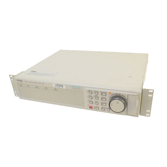
MAIN FEATURES ACCESSORIES This digital video recorder can be used to store images recorded by a monitoring camera onto its built-in hard disk. • Equipped with a large-capacity 3.5-inch hard disk drive. • Recording and playback of images can be carried out using digital signals from a multiplexer. -
Page 6: Part Names
The indicator illuminates while locked. CHANNEL button and indicator ALARM buttons (û ALARM ù) If the digital video recorder is connected to a Sanyo multiplexer that When these buttons are pressed during playback, playback skips to allows decoding of channel information (camera numbers), channels the previous or next alarm recording. -
Page 7: Rear Panel
Rear panel 2 3 4 ALARM CLOCK AC IN RESET ADJUST ALARM ALARM FULL AUDIO VIDEO REMOTE DIGITAL LOOP OUT RS485 SUB IN SUB OUT RS232C TERMINATE PC Card SLOT EJECT RS485 RESET LOOP OUT S-VIDEO PC card slot Alarm connector Connect a network card or SCSI card (sold separately) here. -
Page 8: Connections
CONNECTIONS Be sure to carefully read the Instruction Manuals for all equipment being connected to the digital video recorder. If the connections are incorrect, smoke or operating malfunctions may result. Basic connections Video camera (sold separately) Microphone input ALARM CLOCK AC IN RESET ADJUST... -
Page 9: Digital Multiplexer Connections
Digital multiplexer connections Connect to a multiplexer (MPX-CD163 or CD93) that allows digital connections. Alarm input ALARM CLOCK AC IN RESET ADJUST ALARM ALARM C IN FULL AUDIO VIDEO REMOTE DIGITAL LOOP OUT RS485 SUB IN SUB OUT RS232C TERMINATE PC Card SLOT EJECT RS485... -
Page 10: Built-In Hard Disk
BUILT-IN HARD DISK Hard disk A Normal recording area • When the REC/STOP button is pressed while monitoring is in Recording areas progress, images are recorded in the normal recording area. • The recording areas on the hard disk (normal recording area: 80%, When start and end times are entered for each day of the week and alarm recording area: 19%, archive area: 1%) are established are then enabled, timer recording is automatically carried out in the... -
Page 11: Recording Speed Tables
BUILT-IN HARD DISK Recording speed tables These recording speed tables show the recording times for various picture quality and frame/field settings when recording in the normal recording area of the hard disk (80 GB). They do not include audio recording settings. The setting times for the normal recording area and the alarm recording area represent the picture quality values given in the recording speed tables, multiplied by the percentages for the normal recording area and alarm recording area that have been set using the recording area setting menu commands. -
Page 12: Operating Display
Connect the digital video recorder to a multiplexer that is capable of When the digital video recorder is first turned on, the time appears as decoding Sanyo’s channel information (camera number) and press 00:00:00, and the time starts counting after the date has been set. -
Page 13: Recording Images In The Normal Recording Area
RECORDING IMAGES IN THE NORMAL RECORDING AREA Monitored images are recorded. Normal recording Images can be recorded in the normal recording area while they are being monitored. Insert the power cord into a wall outlet and turn on the Operating display power. -
Page 14: Timer Recording
RECORDING IMAGES IN THE NORMAL RECORDING AREA Timer recording The monitored images can be recorded automatically by setting start and end times for each day of the week. Insert the power cord into a wall outlet and turn on the Operating display power. - Page 15 Timer recording starts when the timer setting time is reached. “a” appears in the operating display and the images being monitored are 10-05-01 recorded in the normal recording area. Recording onto the hard disk proceeds 19:30:00 EN 0.10SEC automatically (default setting) according to the following settings. The settings can be changed between long-period recording and high-quality recording in five steps.
-
Page 16: Recording Images In The Alarm Recording Area
RECORDING IMAGES IN THE ALARM RECORDING AREA Alarm images are recorded Alarm recording Insert the power cord into a wall outlet and turn on the Operating display power. 01-01-01 The POWER indicator illuminates, and after approximately 15 seconds, the 00:00:00 EN 0.10SEC EXIT/OSD indicator illuminates. -
Page 17: Pre-Alarm Recording
RECORDING IMAGES IN THE ALARM RECORDING AREA Pre-alarm images Monitored images are recorded are recorded Pre-alarm recording Insert the power cord into a wall outlet and turn on the Operating display power. 01-01-01 The POWER indicator illuminates, and after approximately 15 seconds, the 00:00:00 EN 0.10SEC EXIT/OSD indicator illuminates. - Page 18 RECORDING IMAGES IN THE ALARM RECORDING AREA When an alarm is received, pre-alarm recording stops automatically and the alarm images are recorded. The “PRE” disappears from the operating display, “ALARM” flashes and the 10-06-01 ALARM 0000 ALARM indicator flashes. 09:30:15 EN 0.10SEC ALARM Note: When the remaining area in the alarm recording area reaches 1%, the ALARM FULL indicator on the front panel flashes.
- Page 19 PLAYING BACK IMAGES RECORDED IN THE NORMAL RECORDING AREA The digital video recorder can play back recorded images in the normal recording area (normal recording, timer recording). Playback operations SEARCH ALARM FRAME/FIELD Normal recording area b Skipping to the previous or next alarm b Switching between frame and field (See page 24.) (See page 22.)
-
Page 20: Playing Back Images Recorded In The Normal Recording
PLAYING BACK IMAGES RECORDED IN THE NORMAL RECORDING AREA Playback Press the PLAY/STOP button. c appears in the operating display and the images recorded in the normal recording area are played back. 10-26-01 PLAY/STOP Note: 11:02:50 EN 0.10SEC • Image playback starts from the point (time) that the recording started. If there is no starting position, or if a reset has been made, the oldest recorded image is played back. - Page 21 PLAYING BACK IMAGES RECORDED IN THE NORMAL RECORDING AREA Zooming the image during playback Press the ZOOM button during playback. The zoom frame (blue) appears in the center of the screen. ZOOM Move the zoom frame to the position where the image is to be enlarged.
- Page 22 PLAYING BACK IMAGES RECORDED IN THE NORMAL RECORDING AREA Viewing still images Press the STILL button during playback. h appears in the operating display and a still image is displayed. 11-17-01 02:38:00 EN 0.10SEC STILL Press the STILL button once more. Still mode is canceled.
-
Page 23: Switching Between Frame And Field Playback
PLAYING BACK IMAGES RECORDED IN THE NORMAL RECORDING AREA Selecting a camera image channel for playback When the digital video recorder has been connected to a multiplexer (sold separately) and camera images have been recorded, you can specify the channel (camera number) for the images recorded and play them back. Press the CHANNEL button while playback is paused. -
Page 24: Searching For Recorded Images
SEARCHING FOR RECORDED IMAGES Images that have been recorded in the alarm recording area and in the archive area can be played back. Furthermore, images can also be searched for by recording date and time, and you can also search for moving objects that have been detected by a motion sensor during image playback. a Alarm search (See page 24.) Archive area <ALARM SEARCH>... -
Page 25: Alarm Search
SEARCHING FOR RECORDED IMAGES Alarm search All alarm recording images in the alarm recording area can be searched for and played back. If pre-alarm images have is recorded, the images immediately before the alarms can also be played back. Press the SEARCH FRAME/FIELD button during recording <SEARCH>... -
Page 26: Alarm Thumbnail Search
SEARCHING FOR RECORDED IMAGES Alarm thumbnail search Alarm images can be searched for and played back from thumbnails. All alarm images recorded in the alarm recording area are displayed as thumbnails. Press the SEARCH FRAME/FIELD button during recording <SEARCH> or when the digital video recorder is stopped. ALARM SEARCH ->... - Page 27 SEARCHING FOR RECORDED IMAGES Time/date search The recording date and time for images in the normal recording area (normal recording and timer recording images) and in the alarm recording area of the hard disk can be specified and the images can be played back. Press the SEARCH FRAME/FIELD button during recording <SEARCH>...
- Page 28 SEARCHING FOR RECORDED IMAGES Turn the shuttle dial clockwise <TIME/DATE SEARCH> A search display appears while searching is in progress, and then a preview RECORDING TOP : 11-05-00 08:00 RECORDING END : 12-22-00 17:00 screen showing the date and time entered appears. SEARCH : Note: If there are no images that match the time exactly, the image closest to DATE...
-
Page 29: Archive Area Search
SEARCHING FOR RECORDED IMAGES Archive area search You can play back images that have been saved (copied) in the archive area. Press the SEARCH FRAME/FIELD button during recording <SEARCH> or when the digital video recorder is stopped. ALARM SEARCH -> ALARM THUMBNAIL SEARCH ->... -
Page 30: Motion Detection Search
• If the digital video recorder is connected to a Sanyo multiplexer that allows decoding of channel information (camera numbers), channels can be specified so that only images from those channels are searched for. If any other type of multiplexer is connected, this setting is not possible. - Page 31 SEARCHING FOR RECORDED IMAGES Turn the shuttle dial clockwise. <MOTION DETECTION SEARCH> The screen changes and the preview screen for camera number 4 appears. SEARCH FROM : NORMAL START : 10-28-01 08:00 START: The date and time for the first image in the selected recording area : 10-28-01 20:00 appears.
- Page 32 SEARCHING FOR RECORDED IMAGES Use the jog dial to move the cursor to PREVIEW, and then <MOTION DETECTION SEARCH> turn the shuttle dial clockwise. The screen showing the SEARCH FROM : NORMAL / CHANNEL : 4 motion sensor settings appear in the preview screen each START : 10-28-01 10:00 time the shuttle dial is turned.
-
Page 33: Saving (Copying) Recorded Images
SAVING (COPYING) RECORDED IMAGES Important images that have been recorded onto the normal recording area or alarm recording area can be copied to a CompactFlash card or to the archive area of the hard disk. Images can be copied to the archive area of the hard disk. -
Page 34: Copying Images From Archive Area To A Compactflash Card
SAVING (COPYING) RECORDED IMAGES Use the jog dial to select ARCHIVE AREA and then turn the shuttle dial clockwise. The cursor moves to HOW MANY. COPY TO : ARCHIVE AREA HOW MANY : 1 PICTURES Turn the shuttle dial clockwise, use the jog dial to change the setting to “10”, and then turn the shuttle dial clockwise. -
Page 35: Compactflash Recording Area
• If you press the COPY button while copying is in progress, copying is canceled. CompactFlash recording area A SANYO folder is created in the root directory. COMPACT FLASH Sub-folders for holding the copied images are created in SANYO 00000001 00000001.JPG... -
Page 36: Copying To A Dds (Dat) Drive
SAVING (COPYING) RECORDED IMAGES Copying to a DDS (DAT) drive Insert an SCSI card (sold separately) for connecting the DDS (DAT) drive into the PC card slot at the rear of the digital video recorder. Images from the archive area can be copied to the DDS (DAT) drive, and images recorded on the DDS (DAT) drive can also be copied to the archive area. - Page 37 SAVING (COPYING) RECORDED IMAGES Reading data from a DDS (DAT) drive into the archive area Note: All of the previously recorded images in the archive area are deleted when images are transferred in this way. Press the COPY button during recording or when the digital <ARCHIVE SET>...
- Page 38 SAVING (COPYING) RECORDED IMAGES Deleting DDS (DAT) drive image data Press the COPY button during recording or when the digital <ARCHIVE SET> video recorder is stopped. BACK UP -> RESTORE -> The ARCHIVE SET screen appears. ERASE -> COPY Use the jog dial to select ERASE and then turn the shuttle <WARNING>...
-
Page 39: Menu Flow Chart And Menu Operations
MENU FLOW CHART AND MENU OPERATIONS MENU flow Settings for recording Settings for operating environment Main menu 1 contains settings that deal mainly with recording. Main menu 2 contains settings that deal mainly with the operating environment. Main menu 1 Main menu 2 <MAIN MENU 1>... -
Page 40: Basic Menu Screen Operations
MENU FLOW CHART AND MENU OPERATIONS Basic menu screen operations Press the EXIT/OSD button. The display returns to the normal screen. Press the MENU button. The MAIN MENU 1 screen appears. If you press the MENU EXIT/OSD button once more, the MAIN MENU 2 screen appears. MENU <MAIN MENU 1>... -
Page 41: Language/Clock Set Settings
LANGUAGE/CLOCK SET SETTINGS This sub-menu lets you set the language for menu screens, the date and time that appear on the screen at all times, and summer time. It also includes a function that lets you synchronize the time settings when more than one device is connected. Main menu 1 Sub-menus Sets the language. -
Page 42: Daylight Saving Setting
LANGUAGE/CLOCK SET SETTINGS DAYLIGHT SAVING setting EXT. CLOCK SET setting (default setting: USE) (default setting: 01:00) This can be used to set the starting time and ending time for daylight If more than two devices are connected at the same time, the time saving. -
Page 43: Video Input Set Setting
If using a multiplexer manufactured by SANYO or some other manufacturer in analog connection mode, connect the SW OUT terminal at the rear of this unit to the SW IN terminal of the multiplexer. This is not necessary if using a SANYO multiplexer in digital connection mode. English... -
Page 44: Recording Area Set Setting
RECORDING AREA SET SETTING Main menu 1 Sub-menus Displays the total hard disk capacity. <MAIN MENU 1> <RECORDING AREA SET> 1.LANGUAGE/CLOCK SET -> TOTAL CAPACITY : 80GB 2.VIDEO INPUT SET -> NORMAL RECORDING AREA : 80 % 3.RECORDING AREA SET ->... -
Page 45: Area Full Reset Setting
RECORDING AREA SET SETTING Turn the shuttle dial counterclockwise. Use the jog dial to move the cursor to the AREA FULL RESET → setting for the NORMAL RECORDING AREA, and The screen changes to show a “WARNING” display. This is a then turn the shuttle dial clockwise. -
Page 46: Recording Conditions Set Setting
RECORDING CONDITIONS SET SETTING This lets you make settings and set overwriting permissions for each recording area when multiple digital video recorders (up to a maximum of three) are connected for series recording. Main menu 1 Sub-menus Sets series recording. <MAIN MENU 1>... -
Page 47: Setting Normal Recording Area Overwrite And Remaining Disk Warning On The Operating Display Section
RECORDING CONDITIONS SET SETTING Setting NORMAL RECORDING AREA When the cursor is at the REMAINING DISK WARNING OVERWRITE and REMAINING DISK setting, turn the shuttle dial clockwise, and then use the jog WARNING on the operating display dial to set the display value for the amount of disk space remaining (example: “5”). -
Page 48: Normal Rec Mode Set Setting
NORMAL REC MODE SET SETTING Main menu 1 Sub-menus Sets the image quality. <MAIN MENU 1> <NORMAL REC MODE SET> 1.LANGUAGE/CLOCK SET -> PICTURE QUALITY : ENHANCED Sets the recording method 2.VIDEO INPUT SET -> FRAME/FIELD RECORDING : FIELD 3.RECORDING AREA SET ->... -
Page 49: Timer Set Setting
TIMER SET SETTING Use the timer function of the digital video recorder to set the times for timer recording. Main menu 1 Sub-menus <MAIN MENU 1> <TIMER SET> Sets the timer. 1.LANGUAGE/CLOCK SET -> WEEK START STOP REC CYCLE The timer must be set when carrying out 2.VIDEO INPUT SET ->... - Page 50 TIMER SET SETTING Press the EXIT/OSD button. Use the jog dial to change from “– –” to “08”, and then turn the shuttle dial clockwise. The display returns to the normal screen. “– – ” (minutes) flashes in the START column. EXIT/OSD Note: •...
-
Page 51: Timer Reservations Spanning More Than 24 Hours
TIMER SET SETTING Timer reservations spanning more than Use the jog dial to change from “TUE” to “WED”, and then 24 hours turn the shuttle dial clockwise. To make 24-hour timer reservations, use lines 7 (SAT) and 8 (DLY) of “–... -
Page 52: Holiday Set Setting
HOLIDAY SET SETTING Main menu 1 Sub-menus <MAIN MENU 1> <HOLIDAY SET> Sets an ordinary day to a holiday. 1.LANGUAGE/CLOCK SET -> 1. ----- 11. ----- 2.VIDEO INPUT SET -> 2. ----- 12. ----- 3.RECORDING AREA SET -> 3. ----- 13. -
Page 53: Alarm Rec Mode Set Setting
ALARM REC MODE SET SETTING Main menu 1 Sets the image quality. <MAIN MENU 1> 1.LANGUAGE/CLOCK SET Sets the recording method (frame or field). 2.VIDEO INPUT SET -> 3.RECORDING AREA SET -> 4.RECORDING CONDITIONS SET -> Sets audio recording. 5.NORMAL REC MODE SET ->... - Page 54 ALARM REC MODE SET SETTING Turn the shuttle dial clockwise, use the jog dial to set the Turn the shuttle dial clockwise, use the jog dial to set the recording method (example: “FRAME”), and then turn the recording speed (example: “0.13”), and then turn the shuttle shuttle dial clockwise.
-
Page 55: Pre-Alarm Recording Setting
ALARM REC MODE SET SETTING Pre-alarm recording setting Use the jog dial to set the recording time duration (example: “5SEC”), and then turn the shuttle dial clockwise. Use the jog dial to move the cursor to the ALARM The cursor moves to ALARM TRIGGER. RECORDING setting, and then turn the shuttle dial clockwise. -
Page 56: Alarm Trigger Setting
ALARM REC MODE SET SETTING Alarm trigger setting Built-in motion sensor settings The monitor screen (-: 8x10) can be displayed on the monitor screen so that detection of suspicious people (alarms) can be carried out Use the jog dial to move the cursor to the ALARM TRIGGER more easily. - Page 57 ALARM REC MODE SET SETTING Use the jog dial to move the cursor to the MOTION SENSOR Turn the shuttle dial clockwise twice. setting, and then turn the shuttle dial clockwise. This completes the motion sensor settings, and the display is The motion sensor screen appears on the normal screen.
-
Page 58: Display Set Setting
DISPLAY SET SETTING Main menu 2 Sub-menus Displays the date on the monitor screen. <MAIN MENU 2> <DISPLAY SET> 1.DISPLAY SET/VIDEO LOSS SET -> DATE : ON Displays the time on the monitor screen. 2.RS-232C/RS-485 SET -> TIME : ON 3.BUZZER SET ->... -
Page 59: Rs-232C/Rs-485 Set Setting
RS-232C/RS-485 SET SETTING Main menu 2 Sub-menus Selects CONTROL. <MAIN MENU 2> <RS-232C/RS-485 SET> 1.DISPLAY SET/VIDEO LOSS SET -> CONTROL : RS-232C Sets communication environment. 2.RS-232C/RS-485 SET -> DATA SPEED : 19200 3.BUZZER SET -> STATUS INFO : *** 4.SECURITY LOCK SET ->... -
Page 60: Rs-485 Selection
RS-232C/RS-485 SET SETTING RS-485 Selection Turn the shuttle dial clockwise, use the jog dial to select an Connect the RS-485 control terminals (A and B) of the digital video address (example: “37”), and then turn the shuttle dial recorder in series with other devices such as a controller, multiplexer clockwise. -
Page 61: Buzzer Set Setting
BUZZER SET SETTING Main menu 2 Sub-menus Sets the buzzer to sound during alarms. <MAIN MENU 2> <BUZZER SET> 1.DISPLAY SET/VIDEO LOSS SET -> ALARM : OFF Sets the buzzer to sound when there is 2.RS-232C/RS-485 SET -> DISK FULL : ON 3.BUZZER SET ->... -
Page 62: Security Lock Set Setting
SECURITY LOCK SET SETTING Passwords for this digital video recorder can be set by the Administrator or the User or both. Setting passwords enables privileges to be set for recording and playback operations. After the security lock has been set, if someone other than the password setter touches an operating button on the unit, the buzzer will sound and a password must be entered. -
Page 63: B User Password Setting
SECURITY LOCK SET SETTING User password setting Use the jog dial to change the setting to “ON”, and then turn Example: To set the password to “AB123456” the shuttle dial clockwise. The cursor moves to USER. Use the jog dial to move the cursor to USER, and then turn the shuttle dial clockwise. -
Page 64: C Recording And Playback Operating Privilege Setting
SECURITY LOCK SET SETTING Recording and playback operating privilege Security lock setting setting At the normal monitoring screen, press and hold the Selection of operating privilege SUHTTLE HOLD button for approximately 3 seconds. The available operations vary depending on the ON/OFF and The LOCK indicator at the front panel illuminates and the buzzer ADMIN/USER settings. -
Page 65: Network Set Setting
NETWORK SET SETTING Main menu 2 Sub-menus Sets LAN card. <MAIN MENU 2> <NETWORK SET> 1.DISPLAY SET/VIDEO LOSS SET -> LAN CARD : LAN1 Sets NETWORK control. 2.RS-232C/RS-485 SET -> NETWORK CONTROL : OFF 3.BUZZER SET -> IP ADDRESS : 192.168. 0. 1 4.SECURITY LOCK SET ->... -
Page 66: Password Setting Setting
NETWORK SET SETTING PASSWORD SETTING setting Turn the shuttle dial clockwise and use the jog dial to select For network connection there are three access levels, each of which network control (example: “ON”), and then turn the shuttle has a password. Each password can consist of a combination of 4 to 8 dial clockwise. - Page 67 NETWORK SET SETTING Repeat this procedure to continue entering “123456”, and then turn the shuttle dial clockwise. The cursor moves to ID2. PASSWORD SETTING : PASSWORD (4-8) : AB123456 : 2222---- : 3333---- As required, use the same procedure to set passwords for ID2 and ID3, and then turn the shuttle dial clockwise.
-
Page 68: Hdd Set Setting
HDD SET SETTING Main menu 2 Sub-menus <MAIN MENU 2> <HDD SET> Initializes hard disk. 1.DISPLAY SET/VIDEO LOSS SET -> DISK1 80GB 2.RS-232C/RS-485 SET -> DISK2 : ---GB 3.BUZZER SET -> DISK INITIALIZE -> Records mirroring. 4.SECURITY LOCK SET -> CAUTION : ALL RECORDING WILL BE ERASED! 5.NETWORK SET ->... -
Page 69: Power Failure/Used Time Display
POWER FAILURE/USED TIME DISPLAY Main menu 2 Sub-menus <MAIN MENU 2> <POWER FAILURE/USED TIME> 1.DISPLAY SET/VIDEO LOSS SET -> POWER FAILURE 2.RS-232C/RS-485 SET -> #020 FAILURE ----- --:-- 3.BUZZER SET -> RECOVER ----- --:-- 4.SECURITY LOCK SET -> 5.NETWORK SET ->... -
Page 70: Interface Specifications
2400, 4800, 9600, 19200 bps Parity None Stop bit Communication protocol A proprietary Sanyo protocol (SSP: Security Serial Protocol) is used. It is recommended that a special controller be used. Contact the place of purchase for further details on obtaining a special controller. English... - Page 71 INTERFACE SPECIFICATIONS RS485 termination switch settings (RS485 TERMINATE) Termination setting If several unit are being connected together, termination settings must also be made. • Set the RS485 termination switch on the rear panel to ON, and set the termination switch of the last device in the series to ON. •...
- Page 72 INTERFACE SPECIFICATIONS Command Table (Table 4) The following table shows all of the commands that can be processed by the digital video recorder. If a command sent does not correspond to a digital video recorder function, the command is received but no operation is carried out. Upper bit Lower bit TIMER ON/OFF...
-
Page 73: Specifications
SPECIFICATIONS Hard disk capacity : 80 GB (Installation of additional hard disk 80 GB (sold separately) possible) Television System : NTSC color signal standard Picture Resolution : 720 x 240 (Field), 720 x 480 (Frame) Compression : M-JPEG Picture Quality : 5 Levels (Basic, Normal, Enhanced, Fine, Super Fine) Recording Type : Frame or Field Recording... - Page 74 OBLIGATIONS In order to obtain warranty service, the product must be delivered to and picked up from an Authorized Sanyo Service Center at the user’s expense, unless specifically stated otherwise in this warranty. The names and addresses of Authorized Sanyo Service Centers may be obtained by calling the toll-free number listed below.
- Page 75 SANYO Electric Co., Ltd. 1AC6P1P2474-A L8HAA/US (0202KP-CZ) Printed in Japan...