Table of Contents
Advertisement
Advertisement
Table of Contents

Related Manuals for Motorola RFS4010 Series


Summary of Contents for Motorola RFS4010 Series
- Page 1 RFS4010 Series RF Switch Installation Guide...
- Page 2 MOTOROLA and the Stylized M Logo are registered in the US Patent & Trademark Office. Symbol is a registered trademark of Symbol Technologies, Inc. All other product or service names are the property of their respective owners. © Motorola, Inc. 2010. All rights reserved.
-
Page 3: Table Of Contents
Contents 1.0 Introduction ......... 1 2.0 Specifications . -
Page 5: Introduction
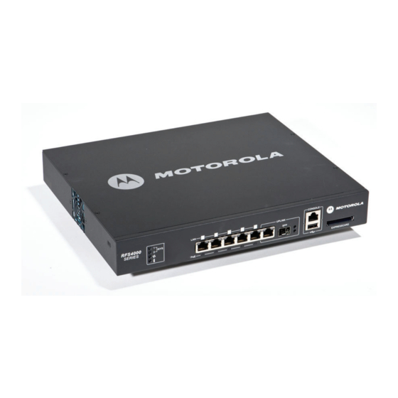
Introduction Introduction The Motorola RFS4010 RF Switch is a member of Motorola’s RFS Series Wireless Switch family. The RFS4010 RF Switch provides centralized Wireless LAN (WLAN) configuration and management by coalescing a network “intelligence” previously spread across physically distributed access points. -
Page 6: Site Preparation
Verify the electrical circuits have appropriate overload protection. • Motorola strongly recommends the use of an Uninterruptible Power Supply (UPS) that supports the RFS4010 RF • Switch power rating. Not using a UPS can result in data loss or equipment damage due to a power surge or power failure. -
Page 7: Specifications
Specifications Specifications 2.1 Physical Specifications Width 304.8mm (12.0in) Height 44.45mm (1.75 in) 1 RU Depth 254mm (10.0 in) Weight 2.15 Kg (4.75 lbs) ° ° ° ° Operating Temperature C - 40 C (32 F - 104 Operating Humidity 5% - 85% RH, non-condensing Operating Altitude 10,000 ft @ 28deg C <... -
Page 8: Led Codes
RFS4010 RF Switch: Installation Guide LED Codes The RFS4010 RF Switch has four vertically-stacked LEDs on its front panel. Each of the six Gigabit Ethernet Ports have two status LEDs. These LEDs display two colors (green & amber), and three lit states (solid, blinking, and off). - Page 9 LED Codes 3.1.1 Start Up / POST (Primary System or Redundant System) System Status 1 LED System Status 2 LED Event Power off Green Blinking Green Blinking Power On Self Test (POST) running Green Solid Green Blinking POST succeeded (Operating System Loading) Green Solid POST succeeded (Normal Operation) Amber Blinking...
- Page 10 RFS4010 RF Switch: Installation Guide 3.1.2 Switch Status (Primary System) System Status 1 LED System Status 2 LED Event Power off Redundancy Feature Enabled Green Solid Primary System Normal Operation No Access Ports Adopted Redundancy Feature Enabled Green Solid Green Solid Primary System Normal Operation Actively Adopting Access Ports No Country Code configured on the switch...
-
Page 11: Temperature Status Led
LED Codes 3.1.4 Fan LED Fan LED Event System Off / POST Start Green Blinking POST in Process Green Solid All System Fans Normal Operation Redundant Cooling Failure Amber Solid System Operational System Cooling Failure Amber Blinking System will be held in reset until the issue is resolved 3.1.5 Temperature Status LED... - Page 12 RFS4010 RF Switch: Installation Guide 3.2 RJ-45 Gigabit Ethernet LEDs Port Port speed activity PoE Status LED...
-
Page 13: Poe Status Led
LED Codes 3.2.1 RJ-45 Port Speed LED Port Speed LED Event 10 Mbps Green Solid 100 Mbps Green Blinking 1000 Mbps Amber Blinking Port Fault 3.2.2 RJ-45 Port Activity LED Port Status LED Event No Link or Administratively shut down Green Solid Link present Green Blinking... -
Page 14: Sfp Gigabit Ethernet Leds
RFS4010 RF Switch: Installation Guide 3.3 SFP Gigabit Ethernet LEDs UPLINK Port speed Port activity 3.3.1 SFP Port Speed LED Port Speed LED Event Green Blinking 1000 Mbps Amber Blinking Module or Tx/Rx Fault Loss 3.3.2 SFP Port Activity LED Port Status LED Event No Link or Administratively shut down... -
Page 15: Hardware Setup
The sections that follow describe detailed connection and cabling information for each port. For software configuration, please see the RFS Series Wireless LAN Switches Wi-NG System Reference Guide available from the Motorola website. -
Page 16: Installing Gigabit Ethernet Sfps
The RFS4010 RF Switch has five RJ-45 Gigabit Ethernet ports and one 1 combo Gigabit (RJ45 + SFP) uplink port. Using the RJ-45 ports requires connecting a Category-6 Ethernet cable to the port. To use the Gigabit SFP port, first install the SFP Module (Motorola Part Number: Fiber-3000-1S-WWR). 4.2.1 Installing Gigabit Ethernet SFPs Open the bail on the transceiver. - Page 17 Hardware Setup Once the SFP transceivers are properly seated in their ports, close the bails to lock the transceivers in place. Close bail to lock SFP transceiver in place...
- Page 18 RFS4010 RF Switch: Installation Guide Insert the fiber optic cables into the installed transceivers.
-
Page 19: Connecting Usb Devices
Hardware Setup 4.3 Connecting USB Devices port The RFS4010 RF Switch contains one USB port for connecting USB flash storage devices to the switch. The switch can use the USB flash storage device for file transfers and firmware updates. Follow the setup instructions below to connect the devices to the switch and then access those devices through the Web UI or Command Line Interface. -
Page 20: Rack Mount Instructions
RFS4010 RF Switch: Installation Guide 4.4 Rack Mount Instructions To install the RFS4010 RF Switch in a rack: Attach the switch to the 1U rack mount kit using the guides provided. Switch Guides Power Supply Guide Cable Management Back Front 1U Rack Mount Kit Attach to Rack Place the power supply unit in the rack mount tray in the space provided. -
Page 21: Console Port
Hardware Setup 4.5 RFS4010 RF Switch Console Port Setup To add the RFS4010 RF Switch to the network and prepare it for initial configuration: Using the supplied console cable (pictured below), connect the RFS4010 RF Switch serial port to an RS-232 (DB-9) serial port on a separate computer (the “configuration computer”). Console Port CONSOLE... - Page 22 4.6 Supplying Power to the RFS4010 RF Switch Power Inlet Plug the power supply (Motorola Part Number: 50-14000-244R) into the power inlet at the back of the RFS4010 RF Switch. Plug the cord into a standard AC outlet with a voltage range of 100 to 240 VAC.
- Page 23 WARNING! An improper shutdown can render the RFS4010 RF Switch inoperable such that it could require service by Motorola Support. Do not remove AC power without first following the shutdown procedure. An abrupt loss of power can corrupt the information stored on the device.
-
Page 24: Verifying The Installation
RFS4010 RF Switch: Installation Guide 3. As soon as the switch resets, depress the reset button on the rear of the switch and continue to hold it through the boot up process until the following message is displayed in the console: Startup config will be RESET to factory default loading linux image 2 ....... -
Page 25: Regulatory Information
This regulatory section applies to the RFS-4010. For more information refer to section 6, Part Numbers, Support, and Sales. All Motorola devices are designed to be compliant with rules and regulations in locations they are sold and will be labeled as required. - Page 26 RFS4010 RF Switch: Installation Guide Class 1 Laser devices are not considered to be hazardous when used for their intended purpose. The following statement is required to comply with US and international regulations: CAUTION Use of controls, adjustments or performance of procedures other than those specified herein may result in hazardous laser light exposure.
- Page 27 Regulatory Information Statement of Compliance Motorola hereby declares that this device is in compliance with all the applicable Directives, 2004/108/EC, 2006/95/EC. A Declaration of Conformity may be obtained from http://www2.symbol.com/doc/ Japan (VCCI) - Voluntary Control Council for Interference Class B ITE この装置は、情報処理装置等電波障害自主規制協議会...
- Page 28 RFS4010 RF Switch: Installation Guide Waste Electrical and Electronic Equipment (WEEE) English: For EU Customers: All products at the end of their life must be returned to Symbol for recycling. For information on how to return product, please go to: http://www.symbol.com/environmental_compliance.
- Page 29 Regulatory Information Italiano: per i clienti dell'UE: tutti i prodotti che sono giunti al termine del rispettivo ciclo di vita devono essere restituiti a Symbol al fine di consentirne il riciclaggio. Per informazioni sulle modalità di restituzione, visitare il seguente sito Web: http://www.symbol.com/ environmental_compliance.
-
Page 30: Part Numbers, Support, And Sales
• Model number or product name • Software type and version number Motorola responds to calls by email, telephone or fax within the time limits set forth in support agreements. If you purchased your Enterprise Mobility business product from a Motorola business partner, contact that business partner for support. -
Page 31: End-User License Agreement
ANOTHER PERSON OR ANY OTHER LEGAL ENTITY, YOU REPRESENT AND WARRANT THAT YOU HAVE THE AUTHORITY TO BIND THAT COMPANY, PERSON OR ENTITY. LICENSE GRANT. Subject to the terms of this Agreement, Motorola, Inc. and/or its subsidiaries ("Licensor") hereby grants Licensee a limited, personal, non-sublicensable, non-transferable, nonexclusive license to use the software that Licensee is about to download or install and the documentation that accompanies it (collectively, the "Software") - Page 32 RFS4010 RF Switch: Installation Guide interrupt, destroy or limit the functionality of any computer software or hardware or telecommunications equipment. Licensee, not Licensor, remains solely responsible for all Content that Licensee uploads, posts, e-mails, transmits, or otherwise disseminates using, or in connection with, the Software. FEES;...
- Page 33 "Restricted Rights" as provided for in FAR, 48 CFR 52.227-14 (JUNE 1987) or DFAR, 48 CFR 252.227- 7013 (OCT 1988), as applicable. The "Manufacturer" for purposes of these regulations is Motorola, Inc., One Symbol Plaza, Holtsville, NY 11742.
-
Page 34: Rfs4010 China Rohs Compliance
(Cables and Cable Assemblies) 塑料和聚合物部件 (Plastic and Polymeric Parts) 光学和光学组件 (Optics and Optical Components) 电池 (Batteries) O: 表示该有毒有害物质在该部件所有均质材料中的含量均在 SJ/T11363-2006 标准规定的 限量要求以下。 X: 表示该有毒有害物质至少在该部件的某一均质材料中的含量超出 SJ/T11363-2006 标准 规定的限量要求。 对销售之日的所售产品,本表表示,公司供应链的电子信息产品可能包含这些物质。注 意:在所售产品中可能会也可能不会含有所有所列的部件。 This table was created to comply with China RoHS requirements for Motorola’s RFS4010. - Page 35 MOTOROLA INC. 1303 E. ALGONQUIN ROAD SCHAUMBURG, IL 60196 http://www.motorola.com 72E-129260-01 Revision B February 2010...