Motorola Netopia 2200 Series User Manual
Motorola netopia 2200-, 3300- or 7000-series gateway user guide
Hide thumbs
Also See for Netopia 2200 Series:
- Administrator's handbook (368 pages) ,
- Specification sheet (5 pages) ,
- Administrator's handbook (254 pages)
Table of Contents
Advertisement
Quick Links
Advertisement
Table of Contents

Related Manuals for Motorola Netopia 2200 Series


Summary of Contents for Motorola Netopia 2200 Series
- Page 1 Administrator’s Handbook ® Motorola Netopia Embedded Software Version 7.7.4 Qwest...
-
Page 2: Copyright
(such as translation, transformation or adaptation) without written permission from Motorola, Inc. Motorola reserves the right to revise this publication and to make changes in content from time to time without obligation on the part of Motorola to provide notification of such revision or change. Motorola provides this guide without warranty of any kind, either implied or expressed, including, but not limited to, the implied warranties of merchantability and fitness for a particular purpose. -
Page 3: Table Of Contents
......26 Set up the Motorola Netopia® Gateway ....27 Configure the Motorola Netopia®... - Page 4 Table of Contents Advanced Setup CHAPTER 3 ......... . 73 Access the Expert Web Interface .
- Page 5 Table of Contents Glossary CHAPTER 6 ..........315 Technical Specifications and Safety Information .
- Page 6 Table of Contents...
-
Page 7: Intended Audience
See “Advanced Setup” on page 73. About Motorola Netopia® Documentation Motorola, Inc. provides a suite of technical information for its 2200 and 3300-series family of intelligent enterprise and consumer Gateways. It consists of: •... -
Page 8: Organization
This guide consists of seven chapters, including a glossary, and an index. It is organized as follows: “Introduction” — Describes the Motorola Netopia® document suite, the purpose of, • the audience for, and structure of this guide. It gives a table of conventions. -
Page 9: Documentation Conventions
Documentation Conventions Documentation Conventions General This manual uses the following conventions to present information: Convention (Typeface) Description Menu commands bold italic monospaced bold italic sans serif Web GUI page links and button names Computer display text terminal User-entered text bold terminal Italic Italic type indicates the complete titles of manuals. - Page 10 Introduction curly ({ }) brackets, with values Alternative values for an argument are separated with vertical bars (|). presented in curly ({ }) brackets, with values separated with vertical bars (|). User-entered text bold terminal type face Variables for which you supply your own italic terminal values type face...
-
Page 11: Overview Of Major Capabilities
UPnP™ feature allows ease of connection with many compatible networked devices. • “Management” on page 16 A Web server built into the Motorola Netopia® Operating System makes setup and maintenance easy using standard browsers. Diagnostic tools facilitate troubleshooting. • “Security” on page 18 Network Address Translation (NAT), password protection, Stateful Inspection firewall... -
Page 12: Wide Area Network Termination
While an Always On connection is convenient, it does leave your network permanently con- nected to the Internet, and therefore potentially vulnerable to attacks. Motorola Netopia®'s Instant On technology furnishes almost all the benefits of an Always- On connection while providing two additional security benefits: •... - Page 13 Wide Area Network Termination • Your network may change address with each connection making it more difficult to attack. When you configure Instant On access, you can also configure an idle time-out value. Your Gateway monitors traffic over the Internet link and when there has been no traffic for the configured number of seconds, it disconnects the link.
-
Page 14: Simplified Local Area Network Setup
URL (Universal Resource Locator) as text to surf to a desired web- site. The Motorola Netopia® DNS Proxy feature allows the LAN-side IP address of the Gateway to be used for proxying DNS requests from hosts on the LAN to the DNS Servers config- ured in the gateway. - Page 15 NAT port maps. This means that applications that sup- port UPnP, and are used with a UPnP-enabled Motorola Netopia® Gateway, will not need application layer gateway support on the Motorola Netopia® Gateway to work through NAT.
-
Page 16: Management
System and security logs • Diagnostics functions Once you have removed your Motorola Netopia® Gateway from its packing container and powered the unit up, use any LAN attached PC or workstation running a common web browser application to configure and monitor the Gateway. - Page 17 Management ☛ NOTE: Your Service Provider may request information that you acquire from these var- ious diagnostic tools. Individual tests may be performed at the command line. (See “Command Line Interface” on page 163.).
-
Page 18: Security
IP address from the ISP. • When NAT is ON, the Motorola Netopia® Gateway “proxies” for the end computer sta- tions on your network by pretending to be the originating host for network communica- tions from non-originating networks. - Page 19 It routes packets received from remote networks to the correct computer on the LAN (Ethernet) interface. • When NAT is OFF, a Motorola Netopia® Gateway acts as a traditional TCP/IP router, all LAN computers/devices are exposed to the Internet. A diagram of a typical NAT-enabled LAN follows: Motorola Netopia®...
-
Page 20: Default Server
Inter- net traffic. Motorola Netopia® Gateways provide special gaming and other service configuration tools that enable you to establish NAT-protected LAN layouts that still provide flexible by-pass capabilities. - Page 21 PAT (NAPT) via the same public IP address for all other hosts on the private LAN subnet. VPN IPSec Pass Through This Motorola Netopia® service supports your independent VPN client software in a trans- parent manner. Motorola has implemented an Application Layer Gateway (ALG) to support multiple PCs running IP Security protocols.
- Page 22 This permits tunnelling from the Gateway without the use of third-party VPN client software on your client PCs. Currently one IPSec VPN tunnel is supported on Motorola Netopia® 2200 and 3300 Series Gateways. Unlike VPN Passthrough, IPsec VPN tunnel is a keyed feature that you can obtained from Motorola.
-
Page 23: Dynamic Dns
Security Dynamic DNS Dynamic DNS support allows you to use the free services of www.dyndns.org. Dynamic DNS automatically directs any public Internet request for your computer's name to your cur- rent dynamically-assigned IP address. This allows you to get to the IP address assigned to your Gateway, even though your actual IP address may change as a result of a PPPoE con- nection to the Internet. -
Page 25: Basic Mode Setup
Most users will find that the basic Quickstart configuration is all that they ever need to use. This section may be all that you ever need to configure and use your Motorola Netopia® Gateway. The following instructions cover installation in Router Mode. -
Page 26: Important Safety Instructions
Important Safety Instructions POWER SUPPLY INSTALLATION Connect the power supply cord to the power jack on the Motorola Netopia® Gateway. Plug the power supply into an appropriate electrical outlet. ☛ CAUTION: Depending on the power supply provided with the product, either the direct plug-in power supply blades, power supply cord plug or the appliance coupler serves as the mains power disconnect. -
Page 27: Set Up The Motorola Netopia® Gateway
Gateway to your power source, PC or local area network, and your Internet access point, whether it is a dedicated DSL outlet or a DSL or cable modem. Different Motorola Neto- pia® Gateway models are supplied for any of these connections. Be sure to enable... - Page 28 Microsoft Windows: Step 1. Navigate to the TCP/IP Properties Control Panel. a. Windows 98, ME. and 2000 versions follow a path like this: Start menu -> Settings -> Control Panel -> Net- work (or Network and Dial-up Connections -> Local Area Connection -> Properties) -> TCP/IP [your_network_card] or Internet Protocol [TCP/ IP] ->...
- Page 29 Set up the Motorola Netopia® Gateway c. Windows Vista is set to obtain an IP address automatically by default. You may not need to configure it at all. To check, open the Networking Control Panel and select Internet Protocol Version 4 (TCP/IPv4).
- Page 30 Apple Menu -> System Prefer- ences -> Network Then go to Step 2. Step 2. Select Built-in Ethernet Step 3. Select Configure Using DHCP Step 4. Close and Save, if prompted. Proceed to “Configure the Motorola Netopia® Gateway” on page...
-
Page 31: Configure The Motorola Netopia® Gateway
This user name and password are separate from the user name and password you will use to access the Internet. You may change them later. You will be challenged for this Admin username and password any time that you attempt to access the Motorola Neto- pia® Gateway’s configuration pages. - Page 32 When you connect to your Gateway as an Administrator, you enter “admin” as the User- Name and the Password you just created. The browser displays the Internet Login page. Enter the User Name and Password supplied by your Internet Service Provider. Connect Click the button.
- Page 33 The Motorola Netopia® Gateway’s home page appears. If you have any questions or encounter problems with your Motorola Netopia® Gateway, refer to the detailed documentation on the Motorola Netopia® CD, or contact your service provider’s technical support helpdesk. Answers to many frequently asked Motorola Netopia® modem questions are also available...
-
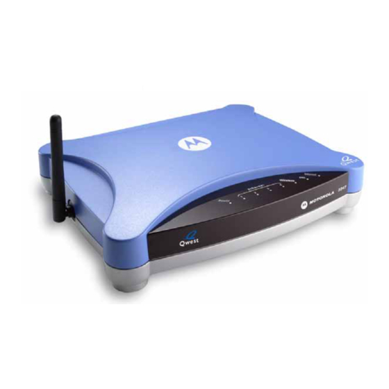
Page 34: Motorola Netopia® Gateway Status Indicator Lights
Colored LEDs on your Motorola Netopia Gateway indicate the status of various port activ- ity. Also, see “Basic Troubleshooting” on page 157 for more information. Motorola Netopia® Gateway 3347-02 status indicator lights Internet Power Wireless Ethernet 1, 2, 3, 4... -
Page 35: Accessing The Web User Interface
Accessing the Web User Interface After you have performed the basic Quickstart configuration, any time you log in to your Motorola Netopia® Gateway you will access the Motorola Netopia® Gateway Home page. http://192.168.0.1 You access the Home Page by typing in your Web browser’s location... -
Page 36: Links Bar
Links Bar The Links Bar is the frame at the left-hand side of the page con- taining the major navigation links. These links are available from almost every page, allowing you to move freely about the site. The headings in the following table are hyperlinks. You can click on any heading to read about that feature. -
Page 37: Home
Home Home Home Page Information The Home page displays information about the following categories: • Connection Information • Router Information • Local Network Help Click the link in the left-hand column of links to display a page of explanatory infor- mation. - Page 38 Home Page Links The links in the left-hand column of the Home page access a series of pages to allow you to monitor, diagnose, and update your router. The following sections give descriptions of these pages.
-
Page 39: Wireless
Home Link: Wireless (supported models only) Wireless When you click , the 3-D Reach Wireless configuration page appears. Enable Wireless The wireless function is not automatically enabled by default. If you check the Enable Wireless checkbox, the Wireless Options are enabled, and the Gateway will provide or broadcast its wireless LAN services. - Page 40 • or enter this name on their clients in order to join this wireless LAN. Privacy The pull-down menu for enabling Privacy offers four settings: WPA-802.1x, WPA-PSK, WEP-Manual, and Off - No Privacy. IT IS STRONGLY RECOMMENDED THAT YOU ENABLE SOME FORM OF PRIVACY FOR THE SECURITY OF YOUR WIRELESS NETWORK.
-
Page 41: Operating Mode
Home Advanced Configuration Options (optional) Advanced Configuration Options button, the Advanced 802.11 When you click the Wireless screen appears. This screen varies its options depending on which form of wire- less Privacy you have selected. Operating Mode The pull-down menu allows you to select and lock the Gateway into the wireless transmis- sion mode you want. - Page 42 • At Startup – the default setting – causes the Motorola Netopia® Gateway at startup to briefly initialize on the default channel, then perform a full two- to three-second scan, and switch to the best channel it can find, remaining on that channel until the next reboot.
- Page 43 Your own wireless network clients, however, must log into the wireless LAN by using the exact SSID of the Motorola Netopia® Router. In addition, if you have enabled WEP or WPA encryption on the Motorola Netopia® Router, your network clients must also have WEP or WPA encryption enabled, and must have the same WEP or WPA encryption key as the Motorola Netopia®...
- Page 44 Privacy • OFF - No Privacy: This mode disables privacy on your network, allowing any wireless users to connect to your wireless LAN. Use this option if you are using alternative secu- rity measures such as VPN tunnels, or if your network is for public use. WEP - Manual: WEP Security is a Privacy option that is based on encryption between •...
- Page 45 Home RADIUS Server authentication RADIUS servers allow external authentication of users by means of a remote authentica- tion database. The remote authentication database is maintained by a Remote Authentica- tion Dial-In User Service (RADIUS) server. In conjunction with Wireless User Authentication, you can use a RADIUS server database to authenticate users seeking access to the wire- less services, as well as the authorized user list maintained locally within the Gateway.
- Page 46 Enter your RADIUS Server information in the appropriate fields: • RADIUS Server Addr/Name: The default RADIUS server name or IP address that you want to use. • RADIUS Server Secret: The RADIUS secret key used by this server. The shared secret should have the same characteristics as a normal password.
- Page 47 Home WPA-PSK One of the easiest ways to enable Privacy on your Wireless network is by selecting WPA-PSK (Wi-Fi Protected Access) from the pull-down menu. The screen expands to allow you to enter a Pre Shared Key. The key can be between 8 and 63 characters, but for best security it should be at least 20 characters.
- Page 48 WEP-Manual Alternatively, you can enable WEP (Wired Equivalent Privacy) encryption by selecting WEP-Manual from the Privacy pull-down menu. You can provide a level of data security by enabling WEP (Wired Equivalent Privacy) for encryption of network data. You can enable 40-, 128-, or 256-bit WEP Encryption (depend- ing on the capability of your client wireless card) for IP traffic on your LAN.
- Page 49 Home WEP - Manual allows you to enter your own encryption keys manually. This is a difficult process, but only needs to be done once. Avoid the temptation to enter all the same char- acters. Encryption Key Size #1 – #4: Selects the length of each encryption key. The longer the key, the stronger the encryption and the more difficult it is to break the encryption.
- Page 50 Enable Multiple Wireless IDs This feature allows you to add additional network identifiers (SSIDs or Network Names) for your wireless network. To enable Multiple Wireless IDs, click the button. The Enable Multiple Wireless IDs screen appears to allow you to add up to three addi- tional Wireless IDs.
- Page 51 Home Privacy modes available from the pull-down menu for the multiple SSIDs are: WPA-PSK, WPA-802.1x, or Off-No Privacy. These additional Wireless IDs are “Closed System Mode” Wireless IDs (see below) that will not be shown by a client scan, and therefore must be manually configured at the client. In addition, wireless bridging between clients is disabled for all members of these addi- tional network IDs.
- Page 52 Click the button, and the Gateway will restart with your new settings. ☛ NOTES: The Gateway supports up to 4 different SSIDs: • One SSID is broadcast by default and has wireless bridging enabled by default. • Three additional SSIDs are in “Closed System Mode” and have wireless bridging disabled.
-
Page 53: Wifi Multimedia
Home WiFi Multimedia WiFi Multimedia is an advanced feature that allows you to prioritize various types of data travelling over the wireless network. Certain types of data that are sensitive to delays, such as voice or video, must be prioritized ahead of other, less delay-sensitive types, such as email. - Page 54 The screen expands. Router EDCA Parameters (Enhanced Distributed Channel Access) govern wireless data from your Gateway to the client; Client EDCA Parameters govern wireless data from the client to your Gateway. ☛ NOTE: It is not recommended that you modify these settings without direct knowl- edge or instructions to do so.
- Page 55 Home • cwMax: (Maximum Contention Window) upper limit in milliseconds of the range of determining final random backoff. The value you choose must be higher than cwMin. • TXOP Limit: Time interval in microseconds that clients may initiate transmissions. (When Operating Mode is B-only, default values are used and this field is not config- urable.) Save Changes Click the...
- Page 56 The screen expands to permit you to add MAC addresses. Click the button. Once it is enabled, only entered MAC addresses that have been set to Allow will be accepted onto the wireless LAN. All unlisted addresses will be blocked, in addition to the listed addresses with Allow disabled.
- Page 57 Home Submit Click the button. Save Changes When you are finished adding MAC addresses click the button. You will be returned to the 802.11 Wireless page. You can Add, Edit, or Delete any of your entries later by returning to this page.
-
Page 58: Gaming
Link: Gaming Gaming When you click , the NAT (Games and Other Services) page appears. NAT (Games and Other Services) allows you to host internet applications when NAT is enabled. You can host different games and software on different PCs. If you uncheck the Enable NAT checkbox, the rest of the information on the page is hidden. - Page 59 Home Each time you enable a software service or game your entry will be added to the list of Service Names displayed on the NAT Configuration page. To remove a game or software from the hosted list, choose the game or software you want Disable to remove and click the button.
- Page 60 Close Combat III: The Russian Combat Flight Sim: WWII Combat Flight Sim 2: WWII Front, v 1.0 Europe Series, v 1.0 Pacific Thr, v 1.0 Dark Reign Delta Force (Client and Server) Delta Force 2 Diablo II Server Dialpad DNS Server Dune 2000 eDonkey 2000 eMule...
- Page 61 Home Roger Wilco Rogue Spear ShoutCast Server SMTP SNMP SSH server StarCraft Starfleet Command StarLancer, v 1.0 Telnet TFTP Tiberian Sun: Command and Conquer Timbuktu Total Annihilation Ultima Online Unreal Tournament Server Urban Assault, v 1.0 VNC, Virtual Network Comput- Westwood Online, Command Win2000 Terminal Server XBox Live Games...
- Page 62 Port Forwarding forwards a range of WAN ports to an IP address on the LAN. Enter the fol- lowing information: Service Name: A unique identifier for the Custom Service. • • Global Port Range: Range of ports on which incoming traffic will be received. Base Host Port: The port number at the start of the port range your Router should use •...
-
Page 63: Static Nat
Home Trigger Ports forwards a range of ports to an IP address on the LAN only after specific out- bound traffic “triggers” the feature. Enter the following information: • Service Name: A unique identifier for the Custom Service. Global Port Range: Range of ports on which incoming traffic will be received. •... - Page 64 This feature allows you to direct unsolicited or non-specific traffic to a designated LAN sta- tion. With NAT “On” in the Router, these packets normally would be discarded. For instance, this could be application traffic where you don’t know (in advance) the port or protocol that will be used.
-
Page 65: Advanced Setup
Home Link: Advanced Setup Advanced Setup allows you to configure a wide variety of specific Router and networking settings. Advanced Setup is for advanced users and system administrators, and most users will not need to modify these settings. If you need to enter Advanced Setup, and Advanced Setup click the link, the Advanced Setup Home page displays. -
Page 66: Status
Link: Status Status When you click the link, the Links Bar expands to display nine statistical sub-head- ings. These screens will vary depending on your Gateway’s model and traffic activity. • “DSL” on page 66 • “ATM” on page 67 •... - Page 67 Home • SN Margin (db): Signal to noise margin, in decibels. Reflects the amount of unwanted “noise” on the DSL line. • Line Attenuation: Amount of reduction in signal strength on the DSL line, in decibels. CRC Errors: Number of times data packets have had to be resent due to errors in •...
- Page 68 IP interfaces Address: Your Router's IP address as seen from your internal network (LAN), and from • the public Internet (WAN) • Netmask: The subnet mask for the respective IP interfaces (LAN and WAN) • Name: The name of each IP interface (example:Eth0, WAN1) Network Routing Table and Host Routing Table The Routing tables display all of the IP routes currently known to your Router.
- Page 69 Home Wireless (supported models only) Wireless When you click , the Wireless Statistics page appears. The Wireless Statistics page: • displays your Router's unique hardware Wireless (MAC) address. • displays detailed statistics about your Wireless LAN data traffic, upstream and down- stream.
-
Page 70: User List
Some browsers, such as Internet Explorer for Windows XP, require that you specify the Motorola Netopia® Gateway’s URL as a “Trusted site” in “Internet Options: Security”. User List User List When you click , the User List Statistics page appears. -
Page 71: Diagnostics
Home Link: Diagnostics This automated multi-layer test examines the functionality of the Router from the physical connections to the data traffic being sent by users through the Router. You enter a web address, such as tftp.netopia.com, or an IP address in the Web Address Test button. -
Page 72: Help
Link: Help Help When you click the link in the left-hand column of links a page of explanatory infor- mation displays. Help (in English only) is available for every page in the Web interface. Here is an example from the Home page:... -
Page 73: Chapter 3 Advanced Setup
Access the Expert Web Interface Advanced Setup CHAPTER 3 Using the Web-based user interface for the Motorola Netopia® 2200 and 3300-series Gateway you can configure, troubleshoot, and monitor the status of your Gateway. Access the Expert Web Interface Open the Web Connection... - Page 74 Advanced Setup Click on the link in the left-hand column of links. The Home Page opens in Advanced Setup.
- Page 75 Access the Expert Web Interface Home Page - Advanced Setup The Advanced Setup Home Page is the summary page for your Motorola Netopia® Gate- way. The links bar at the left provides links to controlling, configuring, and monitoring pages. Critical configuration and operational status is displayed in the center section.
- Page 76 Home Page - Information The Home Page contains a summary of the Gateway’s configuration settings and status. Summary Information Field Status and/or Description Connection Information DSL/WAN Status Wide Area Network may be Waiting for DSL (or other waiting status), Up or Down Connection Up or Down User Name...
-
Page 77: Links Bar
Links Bar Links Bar The Links Bar is the frame at the left-hand side of the page containing the major navigation links. These links are available from every page, allowing you to move freely about the site. The headings in the following table are hyperlinks. You can click on any heading to read about that feature. -
Page 78: Configure
Configure Link: When you click Configure, the Links bar expands to display the con- figuration options available. Advanced options are intended for experienced users and adminis- trators. Exercise great caution when making any changes to Advanced Configuration options. • “Connection” on page 79 •... -
Page 79: Connection
Links Bar Connection Link: When you click Connection, the Connection Configuration page appears. Note: The appearance of this page will vary based on the model and WAN connection you have. Here you can set up or change the way you connect to your ISP. You should only change these settings at your ISP's direction, or by agreement with your ISP. - Page 80 VPI/VCI: These values depend on the way your ISP's equipment is configured. The • default setting is 8/35. With this setting, the router will match the settings your ISP is using, with no input on your part. You probably would not need to change this. Protocol: The authentication and encapsulation protocol is determined by your ISP, •...
- Page 81 Motorola Netopia® Gateway. For Windows XP users, the automatic discovery feature places an icon representing the Motorola Netopia® Gateway automatically in the “My Network Places” folder. Double- clicking this icon opens the Gateway’s web UI. PCs using UPnP can retrieve the Gateway’s WAN IP address, and automatically create NAT port maps.
-
Page 82: Dhcp Server
DHCP Server Link: When you click DHCP Server, the DHCP Server Configuration page appears. This feature simplifies network administration because the Router maintains a list of IP address assignments. Additional computers can be added to your LAN without the hassle of configuring an IP address. - Page 83 Links Bar • Subnet Mask: Specifies the subnet mask of the Router itself. Defaults to the common Class C subnet. • DHCP Start Address: Specifies the first address in the DHCP address range. You can reserve a sequence of up to 253 IP addresses (including up to 64 IP addresses for wireless clients) within a subnet, beginning with the specified address, for dynamic assignment.
- Page 84 Check the Enabled checkbox Submit and click the button. The screen expands to allow you to enter subnet information. If DHCP Server (see below) is not enabled, the DHCP Start Address and DHCP End Address fields do not appear. Enter the Router’s IP address on the subnet in the IP Address field and the subnet mask for the...
-
Page 85: Ip Passthrough
Links Bar IP Passthrough Link: Passthrough, the IP Passthrough Configuration page appears. When you click The IP passthrough feature allows a single PC on the LAN to have the Router’s public address assigned to it. It also provides PAT (NAPT) via the same public IP address for all other hosts on the private LAN subnet. - Page 86 address and subnet mask. If the WAN interface does not have a suitable subnet mask that is usable, for example when using PPP or PPPoE, the DHCP subnet configuration will default to a class C subnet mask. Select either User Configured PC or an IP address displayed in the selec- tion window (these are the IP addresses currently being served to com- puters on your LAN.) If you select “User Configured PC”, you must then configure a local PC to have the pub-...
-
Page 87: Nat
Links Bar Link: When you click NAT, the NAT (Games and Other Services) page appears. NAT (Games and Other Services) allows you to host internet applications when NAT is enabled. You can host different games and software on different PCs. If you uncheck the Enable NAT checkbox, the rest of the information on the page is hidden. - Page 88 Select a PC to host the software from the Select Host Device pull-down menu and click Enable Each time you enable a software service or game your entry will be added to the list of Service Names displayed on the NAT Configuration page. To remove a game or software from the hosted list, choose the game or software you want Disable to remove and click the...
- Page 89 Links Bar Supported Games and Software Age of Empires, v.1.0 Age of Empires: The Rise of Age of Wonders Rome, v.1.0 Asheron's Call Baldur's Gate Battlefield Communicator Buddy Phone Calista IP Phone CART Precision Racing, v 1.0 Citrix Metaframe/ICA Client Close Combat for Windows 1.0 Close Combat: A Bridge Too Far, v 2.0...
- Page 90 Motocross Madness 2, v 2.0 Motocross Madness, v 1.0 MSN Game Zone MSN Game Zone (DX7 an 8 Need for Speed 3, Hot Pursuit Need for Speed, Porsche Play) Net2Phone NNTP Operation FlashPoint Outlaws pcAnywhere (incoming) POP-3 PPTP Quake II Quake III Rainbow Six RealAudio...
- Page 91 Links Bar Define Custom Service To configure a Custom Service, choose whether to use Port Forwarding or Trigger Ports. • Port Forwarding forwards a range of WAN ports to an IP address on the LAN. Trigger Ports forwards a range of ports to an IP address on the LAN only after specific •...
- Page 92 Service Name: A unique identifier for the Custom Service. • Global Port Range: Range of ports on which incoming traffic will be received. • • Base Host Port: The port number at the start of the port range your Router should use when forwarding traffic of the specified type(s) to the internal IP address.
- Page 93 Links Bar Static NAT This feature allows you to: • Direct your Router to forward all externally initiated IP traffic (TCP and UDP protocols only) to a default host on the LAN. • Enable it for certain situations: – Where you cannot anticipate what port number or packet protocol an in-bound appli- cation might use.
-
Page 94: Ipsec
IPSec Link: IPSec When you click on the link, the IPSec configuration screen appears. Your Gateway can support two mechanisms for IPSec tunnels: IPSec PassThrough supports Virtual Private Network (VPN) clients running on LAN- • connected computers. Normally, this feature is enabled. You can disable it if your LAN-side VPN client includes its own NAT interoperability Enable IPSec option. - Page 95 Links Bar Configuring an IPSec VPN Tunnel Use the following procedure to configure your IPSec tunnel. Obtain your configuration information from your network administrator. The tables “Parameter Descriptions” on page 100 describe the various parameters that may be required for your tunnel. Not all of them need to be changed from the defaults for every VPN tunnel.
- Page 96 Table 1: IPSec Tunnel Details Parameter Setup Worksheet Motorola Netopia® Parameter Peer Gateway Gateway Name Peer Internal Network Peer Internal Netmask NAT Enable On/Off PAT Address Negotiation Method Main/Aggressive Local ID Type IP Address Subnet Hostname ASCII Local ID Address/Value...
- Page 97 Links Bar Check the Enable IPSec checkbox. Click Add. The Tunnel Configuration page appears. Enter the tunnel Name. This parameter does not have to match the peer/remote VPN device. Enter the initial group of tunnel parameters. Refer to your “IPSec Tunnel Details Parameter Setup Worksheet” on page 96 and the “Parameter Descriptions”...
- Page 98 Submit Click the button. The Tunnel Details screen appears. Make the Tunnel Details entries. Enter or select the required settings. Soft MBytes, Soft Seconds, Hard MBytes, and Hard Seconds values do not have to match the peer/remote VPN device. Refer to your “IPSec Tunnel Details Parameter Setup Worksheet”...
- Page 99 Links Bar You will be returned to the IPSec configuration screen where your entries are displayed in a list. You can return to this screen at any time to edit or delete your entries. Save Changes Click the button and, when prompted, restart your Router.
- Page 100 Parameter Descriptions The following tables describe SafeHarbour’s parameters that are used for an IPSec VPN tunnel configuration: Table 2: IPSec Configuration page parameters Field Description Name The Name parameter refers to the name of the configured tunnel. This is mainly used as an identifier for the administrator. The Name parameter is an ASCII value and is limited to 31 characters.
- Page 101 Links Bar Table 3: IPSec Tunnel Details page parameters PAT Address If NAT is enabled, this field appears. You can specify a Port Address Trans- lation (PAT) address or leave the default all-zeroes (if Xauth is enabled). If you leave the default. the address will be requested from the remote router and dynamically applied to the Gateway.
- Page 102 Table 3: IPSec Tunnel Details page parameters SA Hash Type SA Hash Type refers to the Authentication Hash algorithm used during SA negotiation. Values supported include MD5 and SHA1. N/A will display if NONE is chosen for Auth Protocol. Invalid SPI Enabling this allows the Gateway to re-establish the tunnel if either the Recovery Netopia Gateway or the peer gateway is rebooted.
- Page 103 Extended Authentication (XAuth), an extension to the Internet Key Exchange (IKE) protocol. The Xauth extension provides dual authentication for a remote user’s Motorola Netopia® Gateway to establish a VPN, autho- rizing network access to the user’s central office. IKE establishes the tun- nel, and Xauth authenticates the specific remote user's Gateway.
-
Page 104: Router Password
Use the following procedure to create or change an Administrative (Admin) password for your Netopia Gateway: • Enter your new password in the New Password field. Motorola’s rules for a Password are: - It can have up to eight alphanumeric characters. - It is case-sensitive. •... -
Page 105: Time Zone
Links Bar Time Zone Link: Time Zone link, the Time Zone page appears. When you click the You can set your local time zone by selecting your time zone from the pull-down menu. This allows you to set the time zone for access controls (and in general). -
Page 106: Vlan
MOCA. This allows great flexibility on how the components of a system are connected to each other. VLANs are part of Motorola’s VGx Virtual Gateway technology which allows individual port- based VLANs to be treated as separate and distinct “channels.” When data is passed to a... - Page 107 (QoS). In effect, a single Motorola gateway acts as separate virtual gateways for each distinct service being delivered.
- Page 108 When configuring VLANs you must define how traffic needs to be forwarded: • If traffic needs to be bridged between LAN and WAN you can create a single VLAN that encompasses the WAN port and LAN ports. • If traffic needs to be routed then you must define four elements: •...
- Page 109 Links Bar An example of multiple VLANs, using a Motorola Netopia® Gateway with VGx managed switch technology, is shown below: A VLAN Model Combining Bridging and Routing...
- Page 110 To configure VLANs check the Enable checkbox. To create a VLAN select a list item from the main VLAN page and click the Edit button. The VLAN Entry page appears. Check the Enable checkbox, and enter a descriptive name for the VLAN.
- Page 111 Links Bar You can create up to 16 VLANs, and you can also restrict any VLAN, and the computers on it, from administering the Gateway. • VLAN Name – A descriptive name for the VLAN. Type – LAN or WAN Port(s) can be enabled on the VLAN. You can choose a type desig- •...
- Page 112 VLAN ID – If you select Global as the VLAN Type, the VLAN ID field appears for you to • enter a VID. This must be a unique identifying number between 1 and 4094. (A VID of zero (0) is permitted on the Ethernet WAN port only.) •...
- Page 113 136) • For Motorola Netopia® VGx technology models, separate Ethernet switch ports are dis- played and may be configured. To enable any of them on this VLAN, check the associated Enable checkbox(es). Typically you will choose a physical port, such as an Ethernet port (example: eth0.1) or...
- Page 114 When you enable an interface, the Tag, Priority, and Promote checkboxes and an • 802.1p Priority Bit pull-down menu appear for that interface. Tag – Packets transmitted from this port through this VLAN must be tagged with the VLAN VID. Packets received through this port destined for this VLAN must be tagged with the VLAN VID by the source.
- Page 115 Links Bar • Select an IP Interface for this VLAN. These selections will vary depending on your IP interfaces. For example, if you have set up multiple VCCs, these will appear in the list as ip-vcc1, ip-vcc2, and so forth. When you select an IP interface, the screen expands to allow you to configure Inter- •...
- Page 116 You can Edit, Clear, Enable, or Disable your VLAN entries by returning to the VLANs page, and selecting the appropriate entry from the displayed list. • Save Changes When you are finished, click the button. • Click the Restart Device button.
- Page 117 Links Bar The screen expands to display the VLAN settings.
- Page 118 Example You want to configure a 3347-02 Gateway with two SSIDs (see “Enable Multiple Wireless IDs” on page 136 for more information) for two VLANs, allowing both access to the Inter- net. One SSID will be in the same VLAN as the four ports of the Ethernet Switch, so that those two networks can communicate.
- Page 119 Links Bar Check the Enable checkbox, and in the VLAN Name box, enter the name you would like. For example, call it Network A. Since this VLAN will be for SSID1 and the Ethernet ports, leave Admin Restricted unchecked. This will give this VLAN access to the Gateway. Submit Click the button.
- Page 120 In this case, select all the physical Ethernet ports: eth0.1 through eth0.4, and wireless ssid1. Select ip-eth-a, the IP interface for the group. This will be Inter-Vlan-Group #1. Check the Group-1 checkbox. These ports will be able to communicate with each other. Click the Submit button.
- Page 121 Links Bar The VLAN Name must be given another unique name. For example, call it Network B. Since this is for the second SSID that we don’t want to be given access to the Gateway, check the Admin Restricted checkbox. Submit Click the button.
- Page 122 In the Port Configuration for VLAN: 2 page, you add the Port Interfaces you want associated with the VLAN. Select the ip-eth-a port interface and check the ssid2 port interface. Make this VLAN a member of Inter-Vlan-Group Group-2. Click the Submit button.
- Page 123 Links Bar Next, create a VLAN to provide the Inter-Vlan-Groups access to the Internet (WAN). For example, call it WAN VLAN. Click the Submit button.
- Page 124 Check the vcc1 checkbox, select the ip-vcc1 IP interface, and check the Inter-Vlan- Group Group-1 and Group-2 checkboxes. Members of Groups 1 and 2 will now be able to communicate with the Internet (WAN), but not with each other. When you are finished, click the Submit button, then the Save Changes...
-
Page 125: Wireless
Links Bar Wireless Link: (supported models only) Wireless When you click , the 3-D Reach Wireless configuration page appears. Enable Wireless The wireless function is automatically enabled by default. If you uncheck the Enable Wire- less checkbox, the Wireless Options are disabled, and the Gateway will not provide or broadcast any wireless LAN services. - Page 126 • or enter this name on their clients in order to join this wireless LAN. Privacy The pull-down menu for enabling Privacy offers four settings: WPA-802.1x, WPA-PSK, WEP-Manual, and Off - No Privacy. IT IS STRONGLY RECOMMENDED THAT YOU ENABLE SOME FORM OF PRIVACY FOR THE SECURITY OF YOUR WIRELESS NETWORK.
- Page 127 Links Bar Advanced Configuration Options (optional) Advanced Configuration Options button, the Advanced 802.11 When you click the Wireless screen appears. This screen varies its options depending on which form of wire- less Privacy you have selected. Operating Mode The pull-down menu allows you to select and lock the Gateway into the wireless transmis- sion mode you want.
- Page 128 Default Channel (1 through 11, for North America) on which the network will broadcast. This is a frequency range within the 2.4Ghz band. Channel selection depends on government regulated radio frequencies that vary from region to region. The widest range available is from 1 to 14. Europe, France, Spain and Japan differ.
- Page 129 Your own wireless network clients, however, must log into the wireless LAN by using the exact SSID of the Motorola Netopia® Router. In addition, if you have enabled WEP or WPA encryption on the Motorola Netopia® Router, your network clients must also have WEP or WPA encryption enabled, and must have the same WEP or WPA encryption key as the Motorola Netopia®...
- Page 130 Privacy • OFF - No Privacy: This mode disables privacy on your network, allowing any wireless users to connect to your wireless LAN. Use this option if you are using alternative secu- rity measures such as VPN tunnels, or if your network is for public use. WEP - Manual: WEP Security is a Privacy option that is based on encryption between •...
- Page 131 Links Bar RADIUS Server authentication RADIUS servers allow external authentication of users by means of a remote authentica- tion database. The remote authentication database is maintained by a Remote Authentica- tion Dial-In User Service (RADIUS) server. In conjunction with Wireless User Authentication, you can use a RADIUS server database to authenticate users seeking access to the wire- less services, as well as the authorized user list maintained locally within the Gateway.
- Page 132 The Configure RADIUS Server screen appears. Enter your RADIUS Server information in the appropriate fields: • RADIUS Server Addr/Name: The default RADIUS server name or IP address that you want to use. • RADIUS Server Secret: The RADIUS secret key used by this server. The shared secret should have the same characteristics as a normal password.
- Page 133 Links Bar WPA-PSK One of the easiest ways to enable Privacy on your Wireless network is by selecting WPA-PSK (Wi-Fi Protected Access) from the pull-down menu. The screen expands to allow you to enter a Pre Shared Key. The key can be between 8 and 63 characters, but for best security it should be at least 20 characters.
- Page 134 WEP-Manual Alternatively, you can enable WEP (Wired Equivalent Privacy) encryption by selecting WEP-Manual from the Privacy pull-down menu. You can provide a level of data security by enabling WEP (Wired Equivalent Privacy) for encryption of network data. You can enable 40-, 128-, or 256-bit WEP Encryption (depend- ing on the capability of your client wireless card) for IP traffic on your LAN.
- Page 135 Links Bar WEP - Manual allows you to enter your own encryption keys manually. This is a difficult process, but only needs to be done once. Avoid the temptation to enter all the same char- acters. Encryption Key Size #1 – #4: Selects the length of each encryption key. The longer the key, the stronger the encryption and the more difficult it is to break the encryption.
- Page 136 Enable Multiple Wireless IDs This feature allows you to add additional network identifiers (SSIDs or Network Names) for your wireless network. To enable Multiple Wireless IDs, click the button. The Enable Multiple Wireless IDs screen appears to allow you to add up to three addi- tional Wireless IDs.
- Page 137 Links Bar Privacy modes available from the pull-down menu for the multiple SSIDs are: WPA-PSK, WPA-802.1x, or Off-No Privacy. These additional Wireless IDs are “Closed System Mode” Wireless IDs (see below) that will not be shown by a client scan, and therefore must be manually configured at the client. In addition, wireless bridging between clients is disabled for all members of these addi- tional network IDs.
- Page 138 Click the button, and the Gateway will restart with your new settings. ☛ NOTES: The Gateway supports up to 4 different SSIDs: • One SSID is broadcast by default and has wireless bridging enabled by default. • Three additional SSIDs are in “Closed System Mode” and have wireless bridging disabled.
- Page 139 Links Bar WiFi Multimedia WiFi Multimedia is an advanced feature that allows you to prioritize various types of data travelling over the wireless network. Certain types of data that are sensitive to delays, such as voice or video, must be prioritized ahead of other, less delay-sensitive types, such as email.
- Page 140 The screen expands. Router EDCA Parameters (Enhanced Distributed Channel Access) govern wireless data from your Gateway to the client; Client EDCA Parameters govern wireless data from the client to your Gateway. ☛ NOTE: It is not recommended that you modify these settings without direct knowl- edge or instructions to do so.
- Page 141 Links Bar • cwMax: (Maximum Contention Window) upper limit in milliseconds of the range of determining final random backoff. The value you choose must be higher than cwMin. • TXOP Limit: Time interval in microseconds that clients may initiate transmissions. (When Operating Mode is B-only, default values are used and this field is not config- urable.) Save Changes...
- Page 142 The screen expands to permit you to add MAC addresses. Click the button. Once it is enabled, only entered MAC addresses that have been set to Allow will be accepted onto the wireless LAN. All unlisted addresses will be blocked, in addition to the listed addresses with Allow disabled.
- Page 143 Links Bar Submit Click the button. Save Changes When you are finished adding MAC addresses click the button. You will be returned to the 802.11 Wireless page. You can Add, Edit, or Delete any of your entries later by returning to this page.
-
Page 144: Status
Status Link: Status When you click the link, the Links Bar expands to display nine statistical sub-head- ings. These screens will vary depending on your Gateway’s model and traffic activity: • “DSL” on page 144 • “ATM” on page 145 •... - Page 145 Links Bar • SN Margin (db): Signal to noise margin, in decibels. Reflects the amount of unwanted “noise” on the DSL line. • Line Attenuation: Amount of reduction in signal strength on the DSL line, in decibels. CRC Errors: Number of times data packets have had to be resent due to errors in •...
- Page 146 IP interfaces Address: Your Router's IP address as seen from your internal network (LAN), and from • the public Internet (WAN) • Netmask: The subnet mask for the respective IP interfaces (LAN and WAN) • Name: The name of each IP interface (example:Eth0, WAN2) Network Routing Table and Host Routing Table The Routing tables display all of the IP routes currently known to your Router.
- Page 147 Links Bar (supported models only) When you click USB, the USB Statistics page appears. The USB Statistics page: • displays your Router's unique hardware (MAC) address. • displays detailed statistics about your LAN data traffic, upstream and downstream. Logs When you click Logs, the Logs page appears. Select a log from the pull-down menu (the pull-down menu is available from every Log page): All: Displays the entire system log.
- Page 148 file can be opened with your favorite text editor. ☛ Note: Some browsers, such as Internet Explorer for Windows XP, require that you specify the Motorola Netopia® Gateway’s URL as a “Trusted site” in “Internet Options: Security”. User List User List When you click , the User List Statistics page appears.
-
Page 149: Diagnostics
Links Bar Diagnostics Link: When you click Diagnostics, the Diagnostics page appears. This automated multi-layer test examines the functionality of the Router from the physical connections to the data traffic being sent by users through the Router. You enter a web address, such as tftp.netopia.com, or a known IP address, in the Web Test button. - Page 150 This sequence of tests takes approximately one minute to generate results. Please wait for the test to run to completion. Each test generates one of the following result codes: Result Meaning * PASS: The test was successful. * FAIL: The test was unsuccessful. * SKIPPED: The test was skipped because a test on which it depended failed.
-
Page 151: Remote Access
This link allows you to authorize a remotely-located person, such as a support technician, to directly access your Motorola Netopia® Gateway. This is useful for fixing configuration problems when you need expert help. You can limit the amount of time such a person will have access to your Gateway. -
Page 152: Update Router
Update Router Link: When you click Update Router, the Software Upgrade page appears. Operating System Software is what makes your Router run and occasionally it needs to be updated. Your Current Software Version is displayed at the top of the page. (example screen –... -
Page 153: Reset Router
Links Bar Reset Router Link: You might need to reset your Router to its factory default state, and clear all of your previ- Reset Router ous settings. The link allows you to do that. When you click the link, you will be challenged to confirm that this is what you want to do. -
Page 154: Restart Router
Restart Router Link: When the Gateway is restarted, it will disconnect all users, initialize all its interfaces, and copy the Operating System Software and feature keys from its internal storage. -
Page 155: Basic Mode
Basic Mode Basic Mode Basic Mode, you will be returned to the Basic Mode Home Page. When you click... -
Page 156: Help
Help Help When you click the link in the left-hand column of links a page of explanatory informa- tion displays. Help is available for every page in the Web interface. Here is an example from the Home page:... -
Page 157: Chapter 4 Basic Troubleshooting
Basic Troubleshooting CHAPTER 4 This section gives some simple suggestions for troubleshooting problems with your Gate- way’s initial configuration. Before troubleshooting, make sure you have • read the Quickstart Guide; • plugged in all the necessary cables; and • set your PC’s TCP/IP controls to obtain an IP address automatically. -
Page 158: Status Indicator Lights
Status Indicator Lights The first step in troubleshooting is to check the status indicator lights (LEDs) in the order outlined in the following section. Motorola Netopia® Gateway 3347-02 status indicator lights Internet Power Wireless Ethernet 1, 2, 3, 4 Action Green when power is on. -
Page 159: Led Function Summary Matrix
Status Indicator Lights LED Function Summary Matrix Power Internet Ethernet Wireless Unlit No power No signal No signal No signal No signal Solid Power on Internet con- Router is con- Synched with Synched with Green nection is nected. Ethernet card WLAN established. - Page 160 • Make sure the you are using the Ethernet cable, not the DSL cable. The Ethernet cable is thicker than the standard telephone cable. • Make sure the Ethernet cable is securely plugged into the Ethernet jack on the PC. •...
-
Page 161: Factory Reset Switch
Factory Reset Switch Factory Reset Switch Lose your password? This section shows how to reset the Netopia Gateway so that you can access the configuration screens once again. ☛ NOTE: Keep in mind that all of your settings will need to be reconfigured. If you don't have a password, the only way to access the Netopia Gateway is the following: Referring to the following diagram, find the round Reset Switch opening. -
Page 163: Chapter 5 Command Line Interface
CHAPTER 5 Command Line Interface The Motorola Netopia® Gateway operating software includes a command line interface (CLI) that lets you access your Motorola Netopia® Gateway over a telnet connection. You can use the command line interface to enter and update the unit’s configuration settings, monitor its performance, and restart it. - Page 164 CONFIG Commands “IP Settings” on page 215 “Syslog” on page 274 “Queue Configuration” on page 231 “Wireless Settings (supported models)” on page 277 “IPMaps Settings” on page 239 “VLAN Settings” on page 288 “Network Address Translation (NAT) Default Settings” “VoIP settings” on page 294 on page 240 “Network Address Translation (NAT) Pinhole Settings”...
-
Page 165: Overview
Overview Overview The CLI has two major command modes: SHELL and CONFIG. Summary tables that list the commands are provided below. Details of the entire command set follow in this sec- tion. SHELL Commands Command Status and/or Description to send ARP request atmping to send ATM OAM loopback clear... - Page 166 view to show configuration information voip to show VoIP info to show who is using the shell...
- Page 167 Overview CONFIG Commands Command Verbs Status and/or Description delete Delete configuration list data help Help command option save Save configuration data script Print configuration data Set configuration data validate Validate configuration settings view View configuration data Keywords ATA remote config options ATM options (DSL only) backup Backup gateway options...
-
Page 168: Starting And Ending A Cli Session
You must know the IP address of the Motorola Netopia® Gateway before you can make a telnet connection to it. By default, your Motorola Netopia® Gateway uses 192.168.0.1 as the IP address for its LAN interface. You can use a Web browser to configure the Motorola Netopia® Gateway IP address. -
Page 169: Using The Cli Help Facility
Using the CLI Help Facility Ending a CLI Session You end a command line interface session by typing quit from the SHELL node of the command line interface hierarchy. Saving Settings In CONFIG mode, the save command saves the working copy of the settings to the Gate- way. -
Page 170: About Shell Commands
Issue administrative commands to restart Motorola Netopia® Gateway functions SHELL Prompt When you are in SHELL mode, the CLI prompt is the name of the Motorola Netopia® Gate- way followed by a right angle bracket (>). For example, if you open a CLI connection to the Netopia- Motorola Netopia®... -
Page 171: Shell Commands
Sends an Address Resolution Protocol (ARP) request to match the nnn.nnn.nnn.nnn IP address to an Ethernet hardware address. clear [yes] Clears the configuration settings in a Motorola Netopia® Gateway. If you do not use the optional qualifier, you are prompted to confirm the clear command. - Page 172 The test timed out without producing a result. Try running the test again. download [ server_address ] [ filename ] [confirm] This command installs a file of configuration parameters into the Motorola Netopia® Gate- way from a TFTP (Trivial File Transfer Protocol) server. The TFTP server must be accessible on your Ethernet network.
- Page 173 Adds the message in the message_string argument to the Motorola Netopia® Gateway diagnostic log. loglevel [ level ] Displays or modifies the types of log messages you want the Motorola Netopia® Gateway loglevel to record. If you enter the command without the optional level argument, the command line interface displays the current log level setting.
- Page 174 DNS information. ping [-s size ] [-c count ]{ hostname | ip_address } Causes the Motorola Netopia® Gateway to issue a series of ICMP Echo requests for the device with the specified name or IP address.
- Page 175 “CD mode is not supported on this plat- form.” reset crash Clears crash-dump information, which identifies the contents of the Motorola Netopia® Gateway registers at the point of system malfunction. reset dhcp server Clears the DHCP lease table in the Motorola Netopia®...
- Page 176 Restarts the heartbeat sequence. reset ipmap Clears the IPMap table (NAT). reset log Rewinds the diagnostic log display to the top of the existing Motorola Netopia® Gateway reset show diagnostic log. The log command does not clear the diagnostic log. The next command will display information from the beginning of the log file.
-
Page 177: Show Crash
SHELL Commands restart [ seconds ] Restarts your Motorola Netopia® Gateway. If you include the optional seconds argument, your Motorola Netopia® Gateway will restart when the specified number of seconds have elapsed. You must enter the complete restart command to initiate a restart. - Page 178 Displays the Differentiated Services and QoS values configured in the Motorola Netopia® Gateway. show dslf device-association Displays LAN devices that conform with the TR111 Gateway requirement. It displays - IP Address, Manufacture OUI and Serial number. show enet [ all ] Displays Ethernet interface statistics maintained by the Motorola Netopia®...
- Page 179 Displays OAM internal information, such as OAM mode, state, configurations, events and OAM statistics. show features Displays standard and keyed features installed in the Motorola Netopia® Gateway. show group-mgmt Displays the IGMP Snooping Table. show ip arp Displays the Ethernet address resolution table stored in your Motorola Netopia® Gateway.
- Page 180 Displays the LAN Host Discovery Table of hosts on the wired or wireless LAN, and whether or not they are currently online. show ip routes Displays the IP routes stored in your Motorola Netopia® Gateway. show ip state-insp Displays whether stateful inspection is enabled on an interface or not, exposed addresses and blocked packet statistics because of stateful inspection.
-
Page 181: Show Log
Displays the current status of a Motorola Netopia® Gateway, the device's hardware and software revision levels, a summary of errors encountered, and the length of time the Motorola Netopia® Gateway has been running since it was last restarted. Identical to the status command. - Page 182 show vlan Displays detail of VLAN status and statistics. Example: show vlan Displaying vlan segment interfaces ==== vlan mode ==== ==== segment 0 port masks ==== PortPort : 00000000-00000000 GlobalPort : 00000000-00000000 SumPort : 00000000-00000000 ==== segment 1 port masks ==== PortPort : 00001006-00000001 GlobalPort : 00000000-00000000...
- Page 183 SHELL Commands SumPort : 00000000-00000000 ==== segment 8 port masks ==== PortPort : 00000000-00000000 GlobalPort : 00000000-00000000 SumPort : 00000000-00000000 ==== segment 9 port masks ==== PortPort : 00000000-00000000 GlobalPort : 00000000-00000000 SumPort : 00000000-00000000 ==== segment 10 port masks ==== PortPort : 00000000-00000000 GlobalPort : 00000000-00000000...
- Page 184 Displays details on connected clients, or more details on a particular client if the MAC address is added as an argument. telnet { hostname | ip_address } [ port ] Lets you open a telnet connection to the specified host through your Motorola Netopia® Gateway.
-
Page 185: Wan Commands
Traces the routing path to an IP destination. upload [ server_address ] [ filename ] [confirm] Copies the current configuration settings of the Motorola Netopia® Gateway to a TFTP (Triv- ial File Transfer Protocol) server. The TFTP server must be accessible on your Ethernet net- work. - Page 186 Use the end-to-end argument to ping a remote end node. reset dhcp client release [ vcc-id ] Releases the DHCP lease the Motorola Netopia® Gateway is currently using to acquire the IP settings for the specified DSL port. The vcc-id identifier is an “index”...
-
Page 187: About Config Commands
) at the CLI SHELL prompt. CONFIG Mode Prompt When you are in CONFIG mode, the CLI prompt consists of the name of the Motorola Neto- pia® Gateway followed by your current node in the hierarchy and two right angle brackets config... -
Page 188: Entering Commands In Config Mode
prompt and pressing R . For example, you move to the IP subnode by entering ETURN and pressing R ETURN Netopia-3000/9437188 (top)>> ip Netopia-3000/9437188 (ip)>> As a shortcut, you can enter the significant letters of the node name in place of the full node name at the CONFIG prompt. -
Page 189: Displaying Current Gateway Settings
Step Mode: A CLI Configuration Technique The Motorola Netopia® Gateway command line interface includes a step mode to auto- mate the process of entering configuration settings. When you use the CONFIG step mode,... - Page 190 Error: Subnet mask is incorrect Global Validation did not pass inspection! validate You can use the command to verify your configuration settings at any time. Your Motorola Netopia® Gateway automatically validates your configuration any time you save a modified configuration.
-
Page 191: Config Commands
If there is a match, the configura- tion is downloaded to the Motorola Netopia® ATA, and the ATA is restarted. Once the Motorola Netopia® ATA is restarted, it comes up with the newly downloaded configuration. - Page 192 set ata profile [ 0... 3 ] ata-dhcpc-vid string Specifies a vendor ID for the specified profile when ata-dhcpc-vid-enable is on. set ata profile [ 0... 3 ] ata-static-wan-ip ip_addr Specifies a static WAN IP address for the specified profile. set ata profile [ 0...
- Page 193 CONFIG Commands set ata profile [ 0... 3 ] ata-outproxy-port port Specifies an outbound proxy server port, typically 5060, for the specified profile. set ata profile [ 0... 3 ] ata-auth-id value Specifies an authorization ID for the specified profile. set ata profile [ 0...
- Page 194 You can use the CLI to set up each ATM virtual circuit. set atm option {on | off } Enables the WAN interface of the Motorola Netopia® Gateway to be configured using the Asynchronous Transfer Mode (ATM) protocol. set atm [vcc n ] option {on | off } Selects the virtual circuit for which further parameters are set.
- Page 195 CONFIG Commands set atm [vcc n ] qos sustained-cell-rate { 1 ... n } If QoS class is set to vbr, then specify the sustained-cell-rate that should apply to the specified virtual circuit. This value should be less than, or equal to the Peak Cell Rate, which should be less than, or equal to the line rate.
- Page 196 When bridging is enabled, the Motorola Netopia® Gateway maintains a table of up to 512 MAC addresses. Entries that are not used within 30 seconds are dropped. If the bridging table fills up, the oldest table entries are dropped to make room for new entries.
- Page 197 CONFIG Commands ☛ NOTE: A filterset can only be configured for the bridge if the system bridge or concur- rent bridging/routing is enabled. set bridge ethernet option { on | off } Enables or disables bridging services for the specified virtual circuit using Ethernet fram- ing.
-
Page 198: Dhcp Settings
IP addresses and provide configuration information to other devices on your net- work dynamically. A device that acquires its IP address and other TCP/IP configuration set- tings from the Motorola Netopia® Gateway can use the information for a fixed period of time (called the DHCP lease). - Page 199 CONFIG Commands choose what group of gen-options is to be served to a particular DHCP Client. See “DHCP Generic Options” on page 200 “DHCP Option Filtering” on page 204. Option Groups refer to gen-options; they do not contain them. Deleting a gen-option from an option group does not delete the option.
- Page 200 DHCP Generic Options You can specify DHCP Generic Options which allow you to configure the content to be served for particular option numbers. set dhcp gen-option name name Specifies a DHCP generic option set named name of one to 15 characters. You can specify up to 20 gen-options.
- Page 201 CONFIG Commands Data Size Option Data Format (bytes) Configure IP address 29 - 31 Flag IP address IP address and mask list Multiples of 8 Flag Unsigned 4 byte integer Flag Unsigned 1 byte integer Unsigned 4 byte integer Flag String (up to 100 characters) 41 - 42 IP address list...
- Page 202 Data Size Option Data Format (bytes) Configure String (up to 100 characters) IP address list Multiples of 4 66 - 67 String (up to 100 characters) 68 - 76 IP address list Multiples of 4 Pascal string list (length byte + data) 78 - 79 Complex Empty...
- Page 203 CONFIG Commands Data Size Option Data Format (bytes) Configure 249 (note) Microsoft uses this instead of 121 Empty set dhcp gen-option data-type [ ascii | hex | dotted-decimal ] Specifies the DHCP gen-option data type: ascii, hex or dotted-decimal. set dhcp gen-option data data Specifies the gen-option data.
- Page 204 DHCP Option Filtering Beginning with Firmware Version 7.7, support for DHCP option filtering is provided via the filterset settings. set dhcp filterset name " string " rule n type [ dhcp-option | hw-address | requested-option ] Specifies a DHCP filterset named string as one of three possible types: The rule can either specify an option and option contents, dhcp-option;...
- Page 205 CONFIG Commands [ pass | discard | continue ] Assigns an absent action to the filterset. If set to pass the absent-pool address is hid- den. set dhcp filterset name " string " rule n match-option-group " option_group *" Assigns the option group named option_group to match. set dhcp filterset name "...
- Page 206 192.168.6.100 set dhcp filterset name "settopbox" rule 1 absent-pool 0.0.0.0 Netopia-3000/9450000 (dhcp)>> set dhcp assigned-filterset " string " Assigns the filterset named string created above to the DHCP configuration.
- Page 207 CONFIG Commands DMT Settings DSL Commands set dmt dsl-annex-support [ off | on ] This controls whether other annex support (just as Annex M) is enabled. Default is off. set dmt type [ lite | dmt | ansi | multi | adsl2 | adsl2+ | readsl2 | adsl2anxm | adsl2+anxm ] Selects the type of Discrete Multitone (DMT) asynchronous digital subscriber line (ADSL) protocol to use for the WAN interface.
- Page 208 (inner or outer pair) are in use on your phone line. Specifying tip_ring forces the inner pair to be used; and A_A1 the outer pair. set dmt metallic-termination [ auto | disabled | always_on ] (not supported on all models) This command allows you to apply a sealing current to “dry” DSL lines so that the wiring doesn’t corrode.
- Page 209 CONFIG Commands set dns secondary-address ip_address 0.0.0.0 Specifies the IP address of the secondary DNS name server. Enter if your network does not have a secondary DNS name server. set dns configured-dns-priority [ 0 - 255 ] Sets the configured DNS priority relative to acquired DNS. These server addresses may be acquired via DHCP (client), PPP, or statically configured.
- Page 210 Dynamic DNS Settings Dynamic DNS support allows you to use the free services of www.dyndns.org. Dynamic DNS automatically directs any public Internet request for your computer's name to your cur- rent dynamically-assigned IP address. This allows you to get to the IP address assigned to your Gateway, even though your actual IP address may change as a result of a PPPoE con- nection to the Internet.
-
Page 211: Igmp Settings
Other uses include updating the address books of mobile computer users in the field, or sending out company newsletters to a distribution list. Since a router should not be used as a passive forwarding device, Motorola Netopia® Gateways use a protocol for forwarding multicasting: Internet Group Management Protocol (IGMP). - Page 212 • IGMP Snooping – enables the Motorola Netopia® Gateway to “listen in” to IGMP traf- fic. The Gateway discovers multicast group membership for the purpose of restricting multicast transmissions to only those ports which have requested them. This helps to reduce overall network traffic from streaming media and other bandwidth-intensive IP...
- Page 213 CONFIG Commands address. When a leave message is received, the querier can check its internal table to see if there are any more clients on this group. If there are none, it immediately sends an IGMP leave message to the upstream querier. •...
- Page 214 set igmp version [ 1 | 2 | 3 ] Sets the IGMP querier version: version 1, version 2, or version 3. If you know you will be communicating with other hosts that are limited to v1, for backward compatibility, select 1; otherwise, allow the default 3.
- Page 215 CONFIG Commands IP Settings You can use the command line interface to specify whether TCP/IP is enabled, identify a default Gateway, and to enter TCP/IP settings for the Motorola Netopia® Gateway LAN and WAN ports. ☛ NOTE: For the DSL platform you must identify the virtual PPP interface [vccn], a num- ber from 1 to 8.
- Page 216 { admin-disabled | none } Specifies restrictions on the types of traffic the Motorola Netopia® Gateway accepts over the DSL virtual circuit. The admin-disabled argument means that access to the device via telnet, web, and SNMP is disabled. RIP and ICMP traffic is still accepted. The none argument means that all traffic is accepted.
- Page 217 IGMP hosts on the LAN interface. set ip dsl vccn igmp-null-source-addr { on | off } Specifies whether you want the Motorola Netopia® Gateway to identify the source IP address of every IGMP packet transmitted from this interface as 0.0.0.0 when mcast-fwd is set to on.
- Page 218 A address ip_address Assigns an IP address to the Motorola Netopia® Gateway on the local area network. The IP address you assign to the local Ethernet interface must be unique on your network. By default, the Motorola Netopia® Gateway uses 192.168.0.1 as its LAN IP address.
- Page 219 255.255.255.0 (Class C subnet mask). set ip ethernet A restrictions { none | admin-disabled } Specifies whether an administrator can open a telnet connection to a Motorola Netopia® Gateway over an Ethernet interface (A = the LAN) to monitor and configure the unit.
- Page 220 Default IP Gateway Settings set ip gateway option { on | off } Specifies whether the Motorola Netopia® Gateway should send packets to a default Gate- way if it does not know how to reach the destination host. set ip gateway interface { ip-address | ppp-vccn } Specifies how the Motorola Netopia®...
- Page 221 [ vccn ] option { on | off } Enables or disables IP routing through the virtual PPP interface. By default, IP routing is turned on. If you turn off IP routing and save the new configuration, the Motorola Netopia® Gateway clears IP routing settings set ip ip-ppp [ vccn ] address ip_address Assigns an IP address to the virtual PPP interface.
- Page 222 0.0.0.0, the peer system must be configured to supply this address. set ip ip-ppp [ vccn ] restrictions { admin-disabled | none } Specifies restrictions on the types of traffic the Motorola Netopia® Gateway accepts over the PPP virtual circuit. The admin-disabled argument means that access to the device via telnet, web, and SNMP is disabled.
- Page 223 IP address on the WAN interface. set ip ip-ppp vcc n mcast-fwd [ on | off ] Specifies whether you want the Motorola Netopia® Gateway interface to act as an IGMP proxy host. set ip ip-ppp vcc n unnumbered [ on | off ] Specifies whether you want the Motorola Netopia®...
- Page 224 set ip ip-ppp vcc n dns acquired-dns-priority [ 0 - 255 ] Sets the priority for DNS acquired via PPP. See “Domain Name System Settings” on page 208 for more information.
- Page 225 Ethernet MAC addresses. Unlike dynamic ARP table entries, static ARP table entries do not time out. You can configure as many as 16 static ARP table entries for a Motorola Netopia® Gate- way. Use the following commands to add static ARP entries to the Motorola Netopia®...
- Page 226 IP Prioritization set ip prioritize [ off | on ] Allows you to support traffic that has the TOS bit set. This defaults to off.
- Page 227 CONFIG Commands Differentiated Services (DiffServ) set diffserv option [ off | on ] Turns the DiffServ option off (default) or on. on enables the service and IP TOS bits are used, even if no flows are defined. Consequently, if the end-point nodes provide TOS set- tings from an application that can be interpreted as one of the supported states, the Gate- way will handle it as if it actively marked the TOS field itself.
- Page 228 set diffserv custom-flows name name protocol [ TCP | UDP | ICMP | other ] direction [ outbound | inbound | both ] start-port [ 0 - 65535 ] end-port [ 0 - 65535 ] inside-ip inside-ip-addr inside-ip-mask inside-ip-netmask outside-ip outside-ip-addr outside-ip-mask outside-ip-netmask qos [ off | assure | expedite | network-control ] Defines or edits a custom flow.
- Page 229 CONFIG Commands • qos – Allows you to specify the Quality of Service for the flow: off, assure, expedite or network-control. These are used both to mark the IP TOS byte and to distribute pack- ets into the queues as if they were marked by the source. QoS Setting TOS Bit Value Behavior...
- Page 230 set diffserv qos dscp-map-1 [ best-effort | assured | expedite | network-control ] set diffserv qos dscp-map-31 [ best-effort | assured | expedite | network-control ] By default, the following settings are used in custom mode: set diffserv qos dscp-map-0 best-effort set diffserv qos dscp-map-1 best-effort set diffserv qos dscp-map-2 best-effort set diffserv qos dscp-map-3 best-effort...
- Page 231 CONFIG Commands Queue Configuration Beginning with Firmware Version 7.7.4, the queuing characteristics of all “N” and “-02” model Gateway’s WAN interface can now be configured for: • strict priority queuing (as currently) • weighted fair queuing • rate-limiting funnel ☛ Note: The configuration mechanism is designed to be flexible enough to accommo- date complex queuing requirements.
- Page 232 set queue name queue_name option [ on | off ] type [ basic | wfq | priority | funnel ] Creates a queue named queue_name and assigns a type: • basic – Basic Queue • wfq – Weighted Fair Queue •...
- Page 233 CONFIG Commands Weighted Fair Queue set queue name wfq option [ on | off ] set queue name wf_queue_name type wfq set queue name wf_queue_name weight-type [ relative | bps ] set queue name wf_queue_name entry n input input_queue_name set queue name wf_queue_name entry n weight weight set queue name wf_queue_name entry n share-bw [ on | off ] set queue name wf_queue_name entry n default-input queue_name Specifies the attributes of the Weighted Fair Queue named wf_queue_name .
- Page 234 set queue name "wfq" entry 3 weight 30000 set queue name "wfq" entry 3 share-bw off set queue name "wfq" entry 4 input "basic_q3" set queue name "wfq" entry 4 weight 40000 set queue name "wfq" entry 4 share-bw off set queue name "wfq"...
- Page 235 CONFIG Commands Priority Queue set queue name priority_queue_name option [ off | on ] set queue name priority_queue_name type priority set queue name priority_queue_name default-input queue_name A priority queue can contain up to 8 input queues. For each input queue, the following is configured: set queue name priority_queue_name entry n input input_queue_name...
- Page 236 Funnel Queue A funnel queue is used to limit the rate of the transmission below the actual line rate: set queue name funnel_queue_name option [ on | off ] set queue name funnel_queue_name type funnel set queue name funnel_queue_name input input_queue_name set queue name funnel_queue_name bps bps Specifies the Funnel Queue named funnel_queue_name attributes.
- Page 237 PPP link may make maintenance of dynamic routes problematic. You can configure as many as 32 static IP routes for a Motorola Netopia® Gateway. Use the following commands to maintain static routes to the Motorola Netopia® Gateway rout-...
- Page 238 Specifies the IP address of the Gateway for the static route. The default Gateway must be located on a network connected to the Motorola Netopia® Gateway configured interface. set ip static-routes destination-network net_address metric integer Specifies the metric (hop count) for the static route.
- Page 239 CONFIG Commands delete ip static-routes destination-network net_address Deletes a static route. Deleting a static route removes all information associated with that route. IPMaps Settings set ip-maps name < name > internal-ip < ip address > Specifies the name and static ip address of the LAN device to be mapped. set ip-maps name <...
- Page 240 Network Address Translation (NAT) Default Settings NAT default settings let you specify whether you want your Motorola Netopia® Gateway to forward NAT traffic to a default server when it doesn’t know what else to do with it. The NAT default host function is useful in situations where you cannot create a specific NAT pin- hole for a traffic stream because you cannot anticipate what port number an application...
- Page 241 CONFIG Commands To set up NAT pinholes, you identify the type(s) of traffic you want to redirect by port num- ber, and you specify the internal host to which each specified type of traffic should be directed. The following list identifies protocol type and port number for common TCP/IP protocols: •...
- Page 242 PPPoE /PPPoA Settings You can use the following commands to configure basic settings, port authentication set- tings, and peer authentication settings for PPP interfaces on your Motorola Netopia® Gate- way. Configuring Basic PPP Settings.
- Page 243 [vccn] lcp-echo-requests { on | off } Specifies whether you want your Motorola Netopia® Gateway to send LCP echo requests. You should turn off LCP echoing if you do not want the Motorola Netopia® Gateway to drop a PPP link to a nonresponsive peer.
- Page 244 [vccn] time-out integer If you specified a connection type of instant-on, specifies the number of seconds, in the range 30 - 3600, with a default value of 300, the Motorola Netopia® Gateway should wait for communication activity before terminating the PPP link.
- Page 245 For example, if the remote peer requires CHAP authentication and has a name and CHAP secret for the Motorola Netopia® Gateway, you must enable CHAP and specify the same name and secret on the Motorola Netopia® Gateway before the link can be established.
- Page 246 PPPoE with IPoE Settings Ethernet WAN platforms set wan-over-ether pppoe [ on | off ] Enables or disables PPPoE on the Ethernet WAN interface. set wan-over-ether pppoe-with-ipoe [ on | off ] Enables or disables the PPPoE with IPoE support on Ethernet WAN, including VDSL, plat- forms when pppoe option is set to on.
- Page 247 CONFIG Commands set ip ip-ppp enet-B option on set ip ip-ppp enet-B address 0.0.0.0 set ip ip-ppp enet-B peer-address 0.0.0.0 set ip ip-ppp enet-B restrictions admin-disabled set ip ip-ppp enet-B addr-mapping on set ip ip-ppp enet-B dns acquired-dns-priority 20 set ip ip-ppp enet-B igmp-null-source-addr off set ip ip-ppp enet-B tx-queue "none"...
- Page 248 set ip ip-ppp vcc1 mcast-fwd [ on | off } Enables or disables multi-cast forwarding on the specified interface. If set to on, this inter- face acts as an IGMP proxy host, and IGMP packets are transmitted and received on this interface on behalf of IGMP hosts on the LAN interface.
- Page 249 These are exchanged between your Gateway and service provider Access Node (AN) devices for network fault management, performance analysis and fault isolation. All VDSL and Ethernet WAN Motorola Netopia Gateways support Ethernet OAM options. More Ethernet Packet-Transfer-Mode (PTM) enabled xDSL Motorola Netopia Gateways will support 802.3ah Ethernet OAM options in future releases.
- Page 250 set ethernet oam ah discovery-timer [ 1 - 300 ] Specifies the discovery timer value for continuity check in seconds. Range is 1 – 300 sec- onds. Default is 1. set ethernet oam ah keepalive-timer [ 5 - 305 ] Specifies the keep-alive timer value in seconds.
- Page 251 CONFIG Commands Command Line Interface Preference Settings You can set command line interface preferences to customize your environment. set preference verbose { on | off } Specifies whether you want command help and prompting information displayed. By default, the command line interface verbose preference is turned off. If you turn it on, the command line interface displays help for a node when you navigate to that node.
- Page 252 Port Renumbering Settings If you use NAT pinholes to forward HTTP or telnet traffic through your Motorola Netopia® Gateway to an internal host, you must change the port numbers the Motorola Netopia® Gateway uses for its own configuration traffic. For example, if you set up a NAT pinhole to forward network traffic on Port 80 (HTTP) to another host, you would have to tell the Motor-...
-
Page 253: Security Settings
BreakWater Basic Firewall’s three settings are: • ClearSailing ClearSailing, BreakWater's default setting, supports both inbound and outbound traffic. It is the only basic firewall setting that fully interoperates with all other Motorola Neto- pia® software features. • SilentRunning Using this level of firewall protection allows transmission of outbound traffic on pre-con- figured TCP/UDP ports. - Page 254 Restore SilentRunning when finished. Basic Firewall Background As a device on the Internet, a Motorola Netopia® Gateway requires an IP address in order to send or receive traffic. The IP traffic sent or received have an associated application port which is dependent on the nature of the connection request.
- Page 255 Enabled Disabled Disabled telnet Motorola Netopia® Enabled Disabled Disabled server http external Enabled Disabled Disabled http Motorola Netopia® server Enabled Disabled Disabled DHCP client Enabled Enabled Disabled DHCP server Not Applicable Not Applicable Not Applicable snmp Enabled Disabled...
- Page 256 When connecting the Motorola Netopia® unit in a telecommuting scenario, the corporate VPN settings will dictate the settings to be used in the Motorola Netopia® unit. If a param- eter has not been specified from the other end of the tunnel, choose the default unless you fully understand the ramifications of your parameter choice.
- Page 257 CONFIG Commands set security ipsec tunnels name "123" The name of the tunnel can be quoted to allow special characters and embedded spaces. set security ipsec tunnels name "123" tun-enable (on) {on | off} This enables this particular tunnel. Currently, one tunnel is supported. set security ipsec tunnels name "123"...
- Page 258 set security ipsec tunnels name "123" IKE-mode pre-shared-key ("") {hex string} page 94 for details about SafeHarbour IPsec tunnel capability. Example: 0x1234 set security ipsec tunnels name "123" IKE-mode neg-method {main | aggressive} page 94 for details about SafeHarbour IPsec tunnel capability. Note: Aggressive Mode is a little faster, but it does not provide identity protection for nego- tiations nodes.
- Page 259 "123" IKE-mode invalid-spi-recovery { off | on } Enables the Gateway to re-establish the tunnel if either the Motorola Netopia® Gateway or the peer gateway is rebooted. set security ipsec tunnels name "123" xauth enable {off | on } Enables or disables Xauth extensions to IPsec, when IKE-mode neg-method is set to aggressive.
- Page 260 set security ipsec tunnels name "123" local-id id_value Specifies the NAT local ID value as specified in the local-id-type for the specified IPsec tunnel, when Aggressive Mode is set. ☛ Note: If subnet is selected, the following two values are used instead: set security ipsec tunnels name "123"...
- Page 261 CONFIG Commands Internet Key Exchange (IKE) Settings The following four IPsec parameters configure the rekeying event. set security ipsec tunnels name "123" IKE-mode ipsec-soft-mbytes (1000) {1-1000000} set security ipsec tunnels name "123" IKE-mode ipsec-soft-seconds (82800) {60-1000000} set security ipsec tunnels name "123" IKE-mode ipsec-hard-mbytes (1200) {1-1000000} set security ipsec tunnels name "123"...
- Page 262 Stateful Inspection Stateful inspection options are accessed by the security state-insp tag. set security state-insp [ ip-ppp | dsl ] vcc n option [ off | on ] set security state-insp ethernet [ A | B ] option [ off | on ] Sets the stateful inspection option off or on on the specified interface.
- Page 263 CONFIG Commands set security state-insp udp-timeout [ 30 - 65535 ] Sets the stateful inspection UDP timeout interval, in seconds. set security state-insp dos-detect [ off | on ] Enables or disables the stateful inspection Denial of Service detection feature. If set to on, the device will monitor packets for Denial of Service (DoS) attack.
- Page 264 exposed-address# " n " protocol [ tcp | udp | both | any ] Sets the protocol for the stateful inspection feature for the exposed address list. Accepted values for protocol are tcp, udp, both, or any. If protocol is not any, you can set port ranges: set security state-insp xposed-addr exposed-address# "...
-
Page 265: Snmp Settings
Identifies the system contact, such as the name, phone number, beeper number, or email address of the person responsible for the Motorola Netopia® Gateway. You can enter up to 255 characters for the contact_info argument. You must put the contact_info argu- ment in double-quotes if it contains embedded spaces. - Page 266 You must put the location_info argument in double-quotes if it contains embedded spaces. SNMP Notify Type Settings set snmp notify type [ v1-trap | v2-trap | inform ] Sets the type of SNMP notifications that the system will generate: • v1-trap –...
- Page 267 CONFIG Commands set snmp v3 ro-account security-name string Adds the specified 1 – 32 character name string as the name of the Read-Only user. set snmp v3 ro-account security-model [ none | auth | auth+priv ] Sets the security model for the Read-Only account: none, authentication, or authentication plus privacy.
- Page 268 set snmp v3 rw-account security-name string Adds the specified 1 – 32 character name string as the name of the Read-Write user. set snmp v3 rw-account security-model [ none | auth | auth+priv ] Sets the security model for the Read-Write account: none, authentication, or authentication plus privacy.
-
Page 269: System Settings
Specifies the name of your Motorola Netopia® Gateway. Each Motorola Netopia® Gateway is assigned a name as part of its factory initialization. The default name for a Motorola Netopia® Gateway consists of the word “Netopia-3000/XXX” where “XXX” is the serial number of the device;... - Page 270 • medium - Medium-level informational messages or greater; includes status messages that can help monitor network traffic. • high - High-level informational messages or greater; includes status messages that may be significant but do not constitute errors. The default. • alerts - Warnings or greater;...
- Page 271 CONFIG Commands set system ftp-server option [ off | on ] Enables or disables a simple FTP server in the Gateway. If enabled, the Gateway will accept binary embedded software images (‘.bin’) files or command line configuration files. Supported FTP commands MODE (data transfer mode (only Streaming supported) NOOP...
- Page 272 A password can be as many as 8 characters. Passwords are case-sensitive. Passwords go into effect immediately. You do not have to restart the Motorola Netopia® Gateway for the password to take effect. Assigning an administrator or user password to a Motorola Netopia®...
- Page 273 Zero Touch refers to automatic configuration of your Motorola Netopia® Gateway. The Motorola Netopia® Gateway has default settings such that initial connection to the Inter- net will succeed. If the zerotouch option is set to on, HTTP requests to any destination IP address except the IP address(es) of the configured redirection URL(s) will access a redi-...
- Page 274 http://<domain-name OR IP address>/optionalPath https://<domain-name OR IP address>/optionalPath:port https://<domain-name OR IP address>/optionalPath <domain-name OR IP address>/optionalPath:port <domain-name OR IP address>/optionalPath If the port number is omitted, port 80 will be assumed. Syslog set system syslog option [ off | on ] Enables or disables system syslog feature.
- Page 275 CONFIG Commands Default syslog installation procedure Access the router via telnet from the private LAN. DHCP server is enabled on the LAN by default. The product’s stateful inspection feature must be enabled in order to examine TCP, UDP and ICMP packets destined for the router or the private hosts.
- Page 276 set system ntp alt-server-address <ip-addr> Type the command to save the configuration • Type save • Exit the configuration interface by typing exit • Restart the router by typing restart The router will reboot with the new configuration in effect.
- Page 277 { off | at-startup | continuous } Specifies the wireless AutoChannel Setting for 802.11G models. AutoChannel is a feature that allows the Motorola Netopia® Gateway to determine the best channel to broadcast automatically. For details, see “AutoChannel Setting”...
- Page 278 set wireless mode { both-b-and-g | b-only | g-only } Specifies the wireless operating mode for connecting wireless clients: both-b-and-g, b- only, or g-only, and locks the Gateway in that mode. ☛ NOTE: If you choose to limit the operating mode to B or G only, clients using the mode you excluded will not be able to connect.
- Page 279 CONFIG Commands set wireless multi-ssid second-ssid-wpa-ver { all | WPA1-only | WPA2-only } set wireless multi-ssid third-ssid-wpa-ver { all | WPA1-only | WPA2-only } set wireless multi-ssid fourth-ssid-wpa-ver { all | WPA1-only | WPA2-only } Specifies the type of WPA version enabled on multiple SSIDs when multi-ssid option is set to on and privacy is set to WPA-PSK.
- Page 280 set wireless no-bridging [ off | on ] When set to on, this will block wireless clients from communicating with other wireless cli- ents on the LAN side of the Gateway. set wireless tx-power [ full | medium | fair | low | minimal ] Sets the wireless transmit power, scaling down the router's wireless transmit coverage by lowering its radio power output.
- Page 281 CONFIG Commands Wireless Multi-media (WMM) Settings Router EDCA Parameters (Enhanced Distributed Channel Access) govern wireless data from your Gateway to the client; Client EDCA Parameters govern wireless data from the client to your Gateway. set wireless wmm option [ off | on ] Enables or disables wireless multi-media settings option, which allows you to fine tune WiFi Multimedia Quality of Service (QoS) by transmitting data depending on Diffserv priority set- tings.
- Page 282 set wireless wmm router-edca video { aifs 1... 255 } set wireless wmm router-edca video { cwmin value } set wireless wmm router-edca video { cwmax value } Sets values for Gateway WMM video parameters. set wireless wmm router-edca best-effort { aifs 1... 255 } set wireless wmm router-edca best-effort { cwmin value } set wireless wmm router-edca best-effort { cwmax value } Sets values for Gateway WMM best effort parameters.
- Page 283 CONFIG Commands set wireless wmm client-edca background { aifs 1... 255 } set wireless wmm client-edca background { cwmin value } set wireless wmm client-edca background { cwmax value } set wireless wmm client-edca background { txoplimit 0... 9999 } Sets values for client WMM background parameters.
- Page 284 Wireless Privacy Settings set wireless network-id privacy option { off | WEP | WPA-PSK | WPA-802.1x } Specifies the type of privacy enabled on the wireless LAN. off = no privacy; WEP = WEP encryption; WPA-PSK = Wireless Protected Access/Pre-Shared Key; WPA-802.1x = Wireless Protected Access/802.1x authentication.
- Page 285 CONFIG Commands For simplicity, it is easiest to have both the Gateway and the client transmit with the same key. The default is 1. set wireless network-id privacy encryption-key1-length {40/64bit, 128bit, 256bit} set wireless network-id privacy encryption-key2-length {40/64bit, 128bit, 256bit} set wireless network-id privacy encryption-key3-length {40/64bit, 128bit, 256bit} set wireless network-id privacy encryption-key4-length...
- Page 286 set wireless mac-auth wrlss-MAC-list mac-address MAC-address_string Enters a new MAC address into the MAC address authorization table. The format for an Ethernet MAC address is six hexadecimal values between 00 and FF inclusive separated by colons or dashes (e.g., 00:00:C5:70:00:04). set wireless mac-auth wrlss-MAC-list mac-address “...
- Page 287 CONFIG Commands RADIUS Server Settings set radius radius-name " server_name_string " Specifies the default RADIUS server name or IP address. set radius radius-secret " shared_secret " Specifies the RADIUS secret key used by this server. The shared secret should have the same characteristics as a normal password.
-
Page 288: Vlan Settings
VLAN Settings You can create up to 8 VLANs, and you can also restrict any VLAN, and the computers on it, from administering the Gateway. See “VLAN” on page 106 for more information. set vlan name name Sets the descriptive name for the VLAN. If no name is specified, displays a selection list of node names to select for editing. - Page 289 CONFIG Commands set vlan name name ports port tag [ off | on ] If set to on, packets transmitted from this port through this VLAN must be tagged with the VLAN VID. Packets received through this port destined for this VLAN must be tagged with the VLAN VID by the source.
- Page 290 Example 1: • A simple example using the “Step” method – Navigate to the VLAN item: Netopia-3000/9437188 (top)>> vlan Netopia-3000/9437188 (vlan)>> set vlan (vlan) node list ... Select (name) node to modify from list, or enter new (name) to create. vlan name (?): vlan1 (vlan1) has been added to the (vlan) list name "vlan1"...
- Page 291 CONFIG Commands Example 2: • An example of a “Triple-Play” setup: set vlan name "LanPorts" type by-port set vlan name "LanPorts" admin-restricted off set vlan name "LanPorts" seg-pbits 0 set vlan name "LanPorts" ports eth0.1 option off set vlan name "LanPorts" ports eth0.2 option on set vlan name "LanPorts"...
- Page 292 set vlan name "Voip_217" ip-interfaces ip-eth-a option off set vlan name "Voip_217" inter-vlan-routing group-1 on set vlan name "Voip_217" inter-vlan-routing group-2 off set vlan name "Voip_217" inter-vlan-routing group-3 off set vlan name "Voip_217" inter-vlan-routing group-4 off set vlan name "PPPoE_11" type global set vlan name "PPPoE_11"...
- Page 293 CONFIG Commands set vlan name "Video_31" type global set vlan name "Video_31" id 31 set vlan name "Video_31" admin-restricted off set vlan name "Video_31" seg-pbits 5 set vlan name "Video_31" ports eth0.1 option on set vlan name "Video_31" ports eth0.1 tag off set vlan name "Video_31"...
-
Page 294: Voip Settings
(PSTN). VoIP calls use an Internet protocol, Session Initiation Protocol (SIP), to transmit sound over a network or the Internet in the form of data packets. Certain Motorola Neto- pia® Gateway models have two separate voice ports for connecting telephone handsets. - Page 295 CONFIG Commands set voip phone [ 0 | 1 ] sip-registrar-setting sip-expires-time [ 0 - 65535 ] Specifies the SIP registration server time-out duration from 0 – 65535 seconds for the specified phone. Default is 3600 (1 hour). set voip phone [ 0 | 1 ] sip-out-proxy-server [ server_name | ip_address ] Specifies the SIP outbound proxy server for the specified phone by fully qualified server name or IP address.
- Page 296 [ 1 | 2 | 3 | 4 | 5 | 6 | 7 | none ] Assigns a priority to the ulaw codec, the common analog voice encoding method used in North America. set voip phone [ 0 | 1 ] codec G729A priority [ 1 | 2 | 3 | 4 | 5 | 6 | 7 | none ] Assigns a priority to the G729 annex A codec, the common analog voice compression implementation used in North America.
- Page 297 CONFIG Commands • inband: sends the DTMF digits as a normal inband tone. • rfc2833: sends the DTMF digits as an event as part of the RTP packet header information. • info: sends the DTMF digits in the SIP INFO message. set voip phone [ 0 | 1 ] sip-advanced-setting sip-end-of-dial-marker [ off | on ] sip-end-of-dial-marker –...
- Page 298 set voip phone [ 0 | 1 ] sip-advanced-setting call-feature call-waiting-option [ off | on ] call-waiting-option – enables or disables call waiting. set voip phone [ 0 | 1 ] sip-advanced-setting call-feature call-conferencing-option [ off | on ] call-conferencing-option – enables or disables 3-way call conferencing. set voip phone [ 0 | 1 ] sip-advanced-setting call-feature subscribe-do-not-disturb-option [ off | on ] subscribe-do-not-disturb-option –...
- Page 299 CONFIG Commands echo-max-attenuation [ 0 - 65535 ] echo-max-attenuation – specifies the maximum attenuation level at which to invoke echo cancellation. Default is 16384. set voip phone [ 0 | 1 ] sip-advanced-setting dsp-settings echo-tail-length [ 0 - 65535 ] echo-tail-length –...
- Page 300 set voip phone: 0 auth-id "4004" set voip phone: 0 codec G711A priority 1 set voip phone: 0 codec G711U priority 2 set voip phone: 0 codec G729A priority 3 set voip phone: 0 codec G726_16 priority 4 set voip phone: 0 codec G726_24 priority 5 set voip phone: 0 codec G726_32 priority 6 set voip phone: 0 codec G726_40 priority 7 set voip phone: 0 sip-advanced-setting sip-dtmf-mode rfc2833...
-
Page 301: Upnp Settings
PCs using UPnP can retrieve the Gateway’s WAN IP address, and automatically create NAT port maps. This means that applications that support UPnP, and are used with a UPnP- enabled Motorola Netopia® Gateway, will not need application layer gateway support on the Motorola Netopia® Gateway to work through NAT. The default is on. - Page 302 DSL Forum LAN Side CPE Configuration (TR-064) is an extension of UPnP. It defines more services to locally manage the Motorola Netopia® Gateway. While UPnP allows open access to configure the Gateway's features, TR-064 requires a password to execute any command that changes the Gateway's configuration.
- Page 303 CONFIG Commands The auto-config server is specified by URL and port number. The format for the ACS URL is as follows: http:// some_url.com : port_number http:// 123.45.678.910 : port_number On units that support SSL, the format for the ACS URL can also be: https:// some_url.com : port_number https:// 123.45.678.910 : port_number...
- Page 304 Backup IP Gateway Settings The purpose of Backup is to provide a recovery mechanism in the event that the primary connection fails. A failure can be either line loss, for example by central site switch failure or physical cable breakage, or loss of end-to-end connectivity. Detection of one of these failures causes the Gateway to switch from using the primary DSL WAN connection to an alternate gateway on the Ethernet LAN.
- Page 305 CONFIG Commands set backup ping-host [ 1 | 2 ] [ name hostname | ip-address ip_address ] Specifies an IP address or resolvable DNS name for the Gateway to ping. set backup auto-recovery [ off | on ] Turns automatic recovery off or on. Default is off. set backup recovery-timeout [ 1 - 10 ] If auto-recovery is set to on, specifies the number of minutes for the system to wait before attempting to switch back to the WAN connection.
- Page 306 VDSL Settings ☛ CAUTION! These settings are for very advanced users and lab technicians. Exercise extreme caution when modifying any of these settings. set vdsl sys-option [ 0x00 - 0xff ] sys-bandplan [ 0x00 - 0xff ] psd-mask-level [ 0x00 - 0xff ] pbo-k1_1 [ 0x00000000 - 0xffffffff ] pbo-k1_2 [ 0x00000000 - 0xffffffff ] pbo-k1_3 [ 0x00000000 - 0xffffffff ]...
- Page 307 CONFIG Commands VDSL Parameter Defaults Parameter Default Meaning sys-option 0x00 VDSL system option(bit0=ntr, 1=margin, 2=ini, 3=pbo, 4=tlan, 5=pbo) sys-bandplan 0x02 VDSL system bandplan(bp_3_998_4=2, bp4_997_3=3, bp5_997_3=4…) psd-mask-level 0x00 VDSL system psd mask(def=0, 1=ansim1cab, 2=ansim2cab, 3=etsim1cab, 4=etsim2cab) pbo-k1_1 0x00 VDSL system power back-off k1_1 pbo-k1_2 0x00 VDSL system power back-off k1_2...
- Page 308 VDSL Parameters Accepted Values Parameter Accepted Values sys-option Bit[0]: NTR_DISABLE Bit[1]: ALW_MARGIN_ADJUST. 1: the SNR margin for the optional band is reduced by up to 2.5 dB, but never below a minimum of 4 dB. Bit[2]: SUPPORT_INI Bit[4]: TLAN Enable Bit[5]: PBO Weak mode Enable (Applicable only when PBO Bit[3]=0.
- Page 309 CONFIG Commands VDSL Parameters Accepted Values Parameter Accepted Values sys-bandplan BP1_998_3 (0x00) BP2_998_3 (0x01) BP998_3B_8_5M (0x01) BP3_998_4 (0x02) BP998_4B_12M (0x02) BP4_997_3 (0x03) BP997_3B_7_1M (0x03) BP5_997_3 (0x04) BP6_997_4 (0x05) BP997_4B_7_1M (0x05) BP7_MXU_3 (0x06) FLEX_3B_8_5M (0x06) BP8_MXU_2 (0x07) BP9_998_2 (0x08) BP10_998_2 (0x09) BP998_2B_3_8M (0x09) BP11_998_2 (0x0A)
- Page 310 VDSL Parameters Accepted Values Parameter Accepted Values psd-mask-level 0x00 -- default mask (old gains from before) 0x01 -- ANSI M1 CAB 0x02 -- ANSI M2 CAB 0x03 -- ETSI M1 CAB 0x04 -- ETSI M2 CAB 0x05 -- ITU-T Annex F (Japan) 0x06 - ANSI M1 Ex 0x07 - ANSI M2 Ex 0x08 -- ETSI M1 Ex...
- Page 311 CONFIG Commands VDSL Parameters Accepted Values Parameter Accepted Values port-bandplan BP1_998_3 (0x00) BP2_998_3 (0x01) BP998_3B_8_5M (0x01) BP3_998_4 (0x02) BP998_4B_12M (0x02) BP4_997_3 (0x03) BP997_3B_7_1M (0x03) BP5_997_3 (0x04) BP6_997_4 (0x05) BP997_4B_7_1M (0x05) BP7_MXU_3 (0x06) FLEX_3B_8_5M (0x06) BP8_MXU_2 (0x07) BP9_998_2 (0x08) BP10_998_2 (0x09) BP998_2B_3_8M (0x09) BP11_998_2 (0x0A)
- Page 312 VDSL Parameters Accepted Values Parameter Accepted Values framing-mode HDLC – 0x80 AUTO – 0x90 ATM – 0x00 band-mod Bit 0, 1: Tx Cfg band 1- All tones on 2- All tones below 640 Khz are turned off 3- All tones below 1.1 Mhz are turned off Bit 2,3: Not used Bit 4,5: Rx Cfg band 1- All tones on...
- Page 313 CONFIG Commands VDSL Parameters Accepted Values Parameter Accepted Values rx-filter 0: using internal filter in Rx path 1: using K1 external filter in Rx path (for Korea VLR Application) 2: using U1 external filter in Rx path (for US / Korea VLR Application) 3: using H1 external filter in Rx path (for 100/100 Application) dying-gasp...
-
Page 315: Chapter 6 Glossary
Glossary CHAPTER 6 10Base-T. IEEE 802.3 specification for Ethernet that uses unshielded twisted pair (UTP) wiring with RJ-45 eight-conductor plugs at each end. Runs at 10 Mbps. 100Base-T. IEEE 802.3 specification for Ethernet that uses unshielded twisted pair (UTP) wiring with RJ-45 eight-conductor plugs at each end. - Page 316 adapter. Board installed in a computer system to provide net- work communication capability to and from that computer sys- tem. address mask. See subnet mask. ADSL. Asymmetric Digital Subscriber Line. Modems attached to twisted pair copper wiring that transmit 1.5-9 Mbps down- stream (to the subscriber) and 16 -640 kbps upstream, depending on line distance.
- Page 317 -----B----- backbone. The segment of the network used as the primary path for transporting traffic between network segments. baud rate. Unit of signaling speed equal to the number of num- ber of times per second a signal in a communications channel varies between states.
- Page 318 Cable that lets you connect a port on one Ethernet hub to a port on another Ethernet hub. You can order an Ethernet crossover cable from Motorola Netopia®, if needed. CSU/DSU. Channel Service Unit/Data Service Unit. Device responsible for connecting a digital circuit, such as a T1 link, with a terminal or data communications device.
- Page 319 datagram. Logical grouping of information sent as a network- layer unit. Compare frame, packet. DCE. Digital Communication Equipment. Device that connects the communication circuit to the network end node (DTE). A modem and a CSU/DSU are examples of a DCE. dedicated line.
- Page 320 domain name. Name identifying an organization on the Inter- net. Domain names consists of sets of characters separated by periods (dots). The last set of characters identifies the type of organization (.GOV, .COM, .EDU) or geographical location (.US, .SE). domain name server. Network computer that matches host names to IP addresses in response to Domain Name System (DNS) requests.
- Page 321 encapsulation. Technique used to enclose information format- ted for one protocol, such as AppleTalk, within a packet format- ted for a different protocol, such as TCP/IP. Encrypt Protocol. Encryption protocol for the tunnel session. Parameter values supported include NONE or ESP. encryption.
- Page 322 ity, the modem signals the computer to stop while it catches up on processing the data in the buffer. See CTS, RTS, xon/xoff. fragmentation. Process of breaking a packet into smaller units so that they can be sent over a network medium that cannot transmit the complete packet as a unit.
- Page 323 hardware handshake. Method of flow control using two con- trol lines, usually Request to Send (RTS) and Clear to Send (CTS). header. The portion of a packet, preceding the actual data, containing source and destination addresses and error-check- ing fields. HMAC.
- Page 324 inbound access, and verifying down to the packet level that the network traffic is only what the customer chooses. The Motor- ola Netopia® Gateway works like a network super traffic cop, inspecting and filtering out undesired traffic based on your security policy and resulting configuration.
- Page 325 -----L----- LCP. Link Control Protocol. Protocol responsible for negotiating connection configuration parameters, authenticating peers on the link, determining whether a link is functioning properly, and terminating the link. Documented in RFC 1331. LQM Link Quality Monitoring. Optional facility that lets PPP make policy decisions based on the observed quality of the link between peers.
- Page 326 modem. Modulator/demodulator. Device used to convert a dig- ital signal to an analog signal for transmission over standard telephone lines. A modem at the other end of the connection converts the analog signal back to a digital signal. MRU. Maximum Receive Unit. The maximum packet size, in bytes, that a network interface will accept.
- Page 327 two-way message exchanges while Aggressive mode only requires 3 total message exchanges. null modem. Cable or connection device used to connect two computing devices directly rather than over a network. -----P----- packet. Logical grouping of information that includes a header and data.
- Page 328 PFS, the key used to protect transmission of data must not be used to derive any additional keys. If the key was derived from some other keying material, that material must not be used to derive any more keys. PING. Packet INternet Groper. Utility program that uses an ICMP echo message and its reply to verify that one network node can reach another.
- Page 329 RIP. Routing Information Protocol. Protocol responsible for dis- tributing information about available routes and networks from one router to another. RJ-11. Four-pin connector used for telephones. RJ-45. Eight-pin connector used for 10BaseT (twisted pair Ethernet) networks. route. Path through a network from one node to another. A large internetwork can have several alternate routes from a source to a destination.
- Page 330 The encryption and authentication keys • Lifetime of encryption keys • The lifetime of the SA • Replay prevention sequence number and the replay bit table • An arbitrary 32-bit number called a Security Parameters Index (SPI), as well as the destination host’s address and the IPSEC protocol identifier, identify each SA.
- Page 331 IP addresses along the proper communication ports in the correct order and that no imposter packets interrupt the packet flow. Packet filtering monitors only the ports involved, while the Motorola Netopia® Gateway analyzes the continuous conversation stream, preventing session hijacking and denial of service attacks.
- Page 332 twisted pair. Cable consisting of two copper strands twisted around each other. The twisting provides protection against electromagnetic interference. -----U----- UTP. Unshielded twisted pair cable. -----V----- VJ. Van Jacobson. Abbreviation for a compression standard documented in RFC 1144. -----W----- WAN. Wide Area Network. Private network facilities, usually offered by public telephone companies but increasingly avail- able from alternative access providers (sometimes called Com- petitive Access Providers, or CAPs), that link business network...
-
Page 333: Description
2200-Series Wireless Models: 1.2"(3.0cm) H, 8.7" (22.0 cm) W, 5.2"(13.2cm) L Communications interfaces: The Motorola Netopia® 2200 and 3300 Series Gateways have an RJ-11 jack for DSL line connections or an RJ-45 jack for cable/DSL modem connections and 1 or 4–... - Page 334 Relative storage humidity: 20 to 80% noncondensing Software and protocols Software media: Software preloaded on internal flash memory; field upgrades done via download to internal flash memory via TFTP or web upload. (does not apply to 3342/3352) Routing: TCP/IP Internet Protocol Suite, RIP WAN support: PPPoE, DHCP, static IP address Security:...
-
Page 335: Agency Approvals
Regulatory notices European Community. This Motorola Netopia® product conforms to the European Community CE Mark standard for the design and manufacturing of information technology equipment. This standard covers a broad area of product design, including RF emissions and immunity from electrical... -
Page 336: Manufacturer's Declaration Of Conformance
This restriction applies regardless of whether the equipment is in or our of warranty. It is the responsibility of users requiring service to report the need for service to our Company or to one of our authorized agents. Service can be obtained at Motorola, Inc., 6001 Shellmound Street, Emeryville, California, 94608. Telephone: 510-597-5400. - Page 337 Manufacturer’s Declaration of Conformance ☛ Important This product was tested for FCC compliance under conditions that included the use of shielded cables and connectors between system components. Changes or modifica- tions to this product not authorized by the manufacturer could void your authority to operate the equipment.
-
Page 338: Important Safety Instructions
Important Safety Instructions Australian Safety Information The following safety information is provided in conformance with Australian safety requirements: Caution DO NOT USE BEFORE READING THE INSTRUCTIONS: Do not connect the Ethernet ports to a carrier or carriage service provider’s telecommunications network or facility unless: a) you have the written consent of the network or facility manager, or b) the connection is in accordance with a connection permit or connection rules. -
Page 339: Cfr Part 68 Information
47 CFR Part 68 Information 47 CFR Part 68 Information FCC Requirements The Federal Communications Commission (FCC) has established Rules which permit this device to be directly connected to the telephone network. Standardized jacks are used for these connections. This equipment should not be used on party lines or coin phones. If this device is malfunctioning, it may also be causing harm to the telephone network;... -
Page 340: Electrical Safety Advisory
REN without a decimal point (e.g., 03 is a REN of 0.3). For earlier products, the REN is separately shown on the label. e) If this equipment, the Motorola Netopia® 2200 or 3300 Series router, causes harm to the telephone network, the telephone company will notify you in advance that temporary discontinuance of service may be required. -
Page 341: Copyright Acknowledgments
Copyright Acknowledgments Copyright Acknowledgments Because Motorola has included certain software source code in this product, Motorola includes the following text required by the respective copyright holders: Portions of this software are based in part on the work of the following: Copyright (c) 1998-2005 The OpenSSL Project. - Page 342 RSA, lhash, DES, etc., code; not just the SSL code. The SSL documentation included with this dis- tribution is covered by the same copyright terms except that the holder is Tim Hudson (tjh@crypt- soft.com). Copyright remains Eric Young's, and as such any Copyright notices in the code are not to be removed.
- Page 343 Copyright Acknowledgments THIS SOFTWARE IS PROVIDED BY THE PROJECT AND CONTRIBUTORS ``AS IS'' AND ANY EXPRESS OR IMPLIED WARRANTIES, INCLUDING, BUT NOT LIMITED TO, THE IMPLIED WARRANTIES OF MER- CHANTABILITY AND FITNESS FOR A PARTICULAR PURPOSE ARE DISCLAIMED. IN NO EVENT SHALL THE PROJECT OR CONTRIBUTORS BE LIABLE FOR ANY DIRECT, INDIRECT, INCIDENTAL, SPECIAL, EXEMPLARY, OR CONSEQUENTIAL DAMAGES (INCLUDING, BUT NOT LIMITED TO, PROCUREMENT OF SUBSTITUTE GOODS OR SERVICES;...
- Page 344 1. Redistributions of source code must retain the above copyright notice, this list of conditions and the following disclaimer. 2. Redistributions in binary form must reproduce the above copyright notice, this list of conditions and the following disclaimer in the documentation and/or other materials provided with the distri- bution.
-
Page 345: Index
Index !! command Symbols Arguments Command shortcuts !! command Command truncation Configuration mode Numerics Keywords Reach Wireless Navigating Configuration 39, Prompt 170, Restart command SHELL mode Access the GUI View command Address resolution table Closed System Mode 42, Administrative restrictions Command Administrator password 73,... - Page 346 denial of service DHCP Hardware address DHCP filtering hijacking DHCP lease table Home Page (Basic Mode) DHCP option filtering Hop count DHCP Server HTTP traffic Diagnostic log 176, Level Diagnostics ICMP Echo IGMP DNS Proxy IGMP Snooping Documentation IP 67, conventions IP address 215, Domain...
- Page 347 Location, SNMP Logging in Password Logs 69, Administrator 73, lost echoes User 73, persistent-log Ping Ping command Magic number Pinholes Memory Port authentication Metric Port Forwarding 61, multi-cast forwarding 217, Port forwarding Port renumbering multiple subnets Multiple Wireless IDs 50, PPPoE Primary nameserver Multiple Wireless SSIDs...
- Page 348 rtsp-passthrough system command system password command Safety Instructions set system syslog Secondary nameserver wireless option Session Initiation command Protocol Set wireless user-auth option bncp command 194, command 195, SHELL Set bridge commands Command Shortcuts Set DMT commands Commands Set dns commands Prompt static-routes SHELL level...
- Page 349 Supported Games VPI/VCI Software 59, System contact, SNMP IPSec Pass Through System diagnostics IPSec Tunnel system idle-timeout Termination Telnet 168, Weighted Fair Queue Telnet command weighted fair queuing Telnet traffic Wide Area Network TFTP Wi-Fi Protected Access 47, TFTP server Toolbar 36, Wired Equivalent Privacy 48, TraceRoute...
- Page 351 Motorola Netopia® 2200-, 3300- or 7000-series Motorola, Inc. 6001 Shellmound Street Emeryville, CA 94608 October, 2007...