
Related Manuals for GE Phasor XS


Summary of Contents for GE Phasor XS
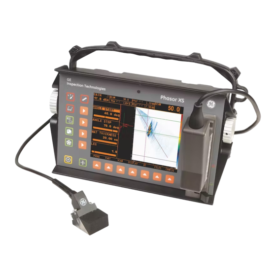
- Page 1 Inspection Technologies Phasor XS™ Quick Reference Guide 021-247-407, rev. 2 ©2008 General Electric Company. All rights reserved. We reserve the right to technical modifications without prior notice.
- Page 2 Guide to the Keypad • -- Mode Selector: Phased Array or Conventional Operating Modes • -- View Select: Frame and/or A-Scan • -- Gain Increment/Decrement: Press and hold to change between digital and analog gain • -- ZOOM View: Expand the display to entire screen Press again to return to normal view mode •...
- Page 3 Guide to the Keypad cont... • -- Power Key: On and off • -- Test Key: Switches from Home to Knob Menu • Function Rotary Knob – Rotate the right-hand knob to change the value of the selected function. • Gain Rotary Knob –...
- Page 4 Setting Up • Press • Press to choose between PHASED ARRAY and CONVENTIONAL • Set units of measurement and operating language by pressing to activate the CONFIG menu. Then activate the REGIONAL submenu. Press next to UNITS or LANGUAGE and turn the Function Knob to adjust.
- Page 5 • Other basic features to adjust are accessed as follows • Date – CONFIG then STARTUP • Time – CONFIG then STARTUP • Display Brightness – CONFIG then STARTUP • Background Color – DISPLAY then BACKGRND • Amplitude Color Palette – DISPLAY then IMAGE •...
- Page 6 Connecting a Probe Move the connector release lever to the open (left) position. Attach the phased array probe connector the front of the instrument so that the connector’s attached cable points upward. Then move the release lever to the right. Orient connector with Phased Array cable pointing up...
- Page 7 Configuring for a Probe and Wedge Access the probe and wedge settings by pressing to activate the PROBE menu. Then activate the PRB GEO submenu. Press next to FREQUENCY, or NUMBER of ELEMENT, or PITCH to input values printed on the probe body. Other probe and wedge features are adjusted as follows: •...
- Page 8 Configuring for a Probe and Wedge Access the probe and wedge settings by pressing to activate the PROBE menu. Wedge features are adjusted as follows: • Wedge Offset Z – PROBE then WDGE GEO (user measured from Probe Index Point to contact surface – set to 0 when no wedge is installed) •...
- Page 9 Configuring for a Probe and Wedge...
- Page 10 Configuring for a Probe and Wedge Markings on the probe body indicate the location of element 1 and the direction that additional elements are arranged. To define the orientation of the probe’s elements with respect to the wedge’s geometry, access PROBE menu then WDGE DAT submenu.
- Page 12 Defining the Scan – LINEAR The sequence in which the phased array probe’s elements fire are defined using features located in the SCAN menu. For LINEAR scan types set the following: • SCAN TYPE – ELECTRNC (choose linear) • WAVE TYPE – ELECTRNC (shear or longitudinal) •...
- Page 13 Defining the Scan - SECTOR The sequence and pattern at which the phased array probe’s ele- ments fire are defined using features located in the SCAN menu. For SECTOR scan types set the following: • SCAN TYPE – ELECTRNC (choose sector) •...
- Page 14 Pulser and Receiver Setup • Access the UT menu to set the Pulser and Receiver operation Pulser Voltage – PULSER • Pulser Width (in nanoseconds) – PULSER [(1/probe frequency) /2] • Receiver Frequency – RECEIVER (includes filter settings) • Rectification – RECEIVER (includes halfwave, fullwave, and RF)
- Page 15 Gate Position and Operating Modes The instrument has two gates (A and B) which are configured by first pressing to access the UT menu: • Select Gate to be Positioned – GATE POS • Gate Starting Point – GATE POS •...
- Page 16 Viewing Scans With the phased array probe coupled to a test piece, there are various ways to view the resulting scans and measured data. Press to choose between A-Scan, Sector (or Linear) Scan, or both A and Sector (or Linear Scan). Press to access the DISPLAY menu and determine the measured results displayed as follows :...
- Page 17 • Press the LEG to change the number of displayed Legs (which represent each pass of the ultrasound through the test piece). • Press , UT, BASE, DISPLAY DELAY to adjust the Display Delay • Press to set the Gain Increment Value -- The amount of gain change with each click of the Gain Knob.
- Page 18 Viewing Measured Results To determine which measured results are displayed, press access the DISPLAY menu • Set Readings in Each of the Four Small Boxes – RESULTS1 • Set Readings in the Large Box – RESULTS2 CHOICES INCLUDE: BEAM— Angular position of the Beam Cursor P%A/B—...
- Page 19 PDA/B— Material depth of all beams in scan currently captured by Gate A or B. PZA/B— Minimum material depth (incorrected according to material thickness) of all beams in scan currently captured by Gate A or B A%A/B— Amplitude (as a % of full-screen height) of the highest echo to cross A-Gate or B-Gate in the beam selected by the beam cursor.
- Page 20 point (PIP) to the reflector represented by the A-Gate echo. DA/B— Material-thickness depth from the testpiece surface, volume corrected. ZA— Depth from surface, angle corrected, without leg correction according to material thickness. OFF— No reading will be displayed in the reading box.
- Page 21 Zero Offset If origin offset = 0, measurement are done from the front wedge P (for origin offset = 0) Volume Corrected Backwall Angle Corrected...
- Page 22 <>Zero Offset If origin offset is less than or greater than zero: Origin offset P<0 P>0 Backwall...
- Page 23 Freezing the Display The displayed image and measured values can be frozen by pressing . The freeze menu appears across the bottom of the display. Use these features to manipulate or evaluate the frozen image. CURSOR 1—Operate a horizontal cursor with the Gain Knob and a Vertical or Beam Cursor with the Function Knob.
- Page 24 MEAS 1—Select up to four READING options that correspond to the point defined by the intersection of CURSOR 1’s horizontal and vertical components. MEAS 2—Select up to four READING options that correspond to the intersecting point defined by the intersection of CURSOR 2’s horizontal and vertical components.
- Page 25 Working with Data Sets Instrument settings and report contents can be stored in a data set file. When recalled, instrument settings are automatically returned to those found in the stored data set. Access the data set related functions by pressing to activate the FILES menu.
- Page 26 • SD CARD – Primary destination for data sets • DIALOG PROBE – Abbreviated data sets can be stored in dialog probes • With the desired data set name input, press next to ENTER to complete the data set creation process. •...
- Page 27 Working with Data Sets Instrument settings and report contents can be stored in a data set file. Stored data sets can be deleted or edited. Access the data set related functions by pressing to activate the FILES menu. An existing Data Set is deleted as follows (refer to Card 2 for help in making adjustments): •...
- Page 28 An existing and active Data Set is edited, as follows: With the data set active, change instrument settings as desired. • Press next to ACTION until STORE DATASET appears. • Press next to SOURCE/DEST until the current data set’s storage location appears. •...
- Page 29 Generating Reports Reports can be generated and stored on the instrument’s SD card. These reports can contain various user-selected components includ- ing instrument settings, displayed image, report header, and memo. Reports are generated in much the same way as a data set file (refer to Card 2 for help in making adjustments): •...
- Page 30 IMAGE IN REPORT – Set to YES to include display image • Press next to ACTION until STORE REPORT appears. • Press twice next to FILENAME. Use the two knobs and the instrument’s text-entry feature to input the new report’s name. •...
- Page 31 Contact Us France Germany GE Inspection Technologies GE Inspection Technologies GE Inspection Technologies 50 Industrial Park Rd. 68 chemin des Ormeaux Robert-Bosch-Strasse Lewistown, PA 17044 F-69760 Limonest T: +49.2233.601.111 T: 717.242.0327 T: +33.472.179.216 F: +49.2233.601.555 F: 717.242.2606 F: +33.472.179.254 UK & Ireland...