
Related Manuals for Canon R-F10


Summary of Contents for Canon R-F10
- Page 1 FULL AUTO REF Operation Manual Before using the instrument, be sure to read this manual thoroughly. Keep the manual in easy-to-access place.
- Page 2 Also, medical products must be used only by a qualified person. 2. In no event will Canon be liable for direct or indirect consequential damage arising out of the use of this product.
- Page 3 Safety Information Regulations For U. S. A. This instrument is a CLASS I EQUIPMENT and TYPE B APPLIED PARTS according to UL2601-1. Do not make any changes or modifications to the equipment unless otherwise specified in the manual. If such changes or modifications should be made, you could be required to stop operation of the equipment.
- Page 4 Safety Information ISO15004 This report provides information about the hazard to the examinee’s eyes in compliance with ISO15004 (1997). 1. The spectral characteristics of radiant flux exiting from this instrument are as follows: Spectral irradiance (relative) Refractometry IRED Outer eye illumination IRED Eye fixation target illumination LED Irradiance (relative)
- Page 5 Safety Information If the value of radiance was 40 [mW/cm2/sr], 6 minutes would be needed to reach the rec- ommended limit. That is, the retinal exposure dose for a photochemical hazard is a product of the radiance and the exposure time. Since La and Lb of this instrument are extremely low, the risk of the photochemical hazard is also very low.
-
Page 6: General Safety Information
Safety Information General Safety Information Follow the safety instructions in this manual and all warnings and cautions printed on the warning labels. Ignoring such cautions or warnings while handling the product may result in injury or accident. Be sure to read and fully understand the manual before using this product. Keep this manual for future reference. -
Page 7: Power Supply
Safety Information Installation Operation f i c t l u t n i i a t , s l i t a Power Supply t a l t l u c / t . l a t i n t l u . - Page 8 Safety Information Handling y f i t l u a t l , s t . y r . t n l a f . y r p i l s l l , t n q i l e l l t l u c t i e l t...
-
Page 9: Maintenance And Inspection
Safety Information When Problem Occurs o l l i , r c t i e l t i t a l l e q i l e l l Maintenance and Inspection c t i t l u c t i e l t , l o a l f... - Page 10 Safety Information Rating Plate and Warning Label The R-F10 has a rating plate and a warning label on it. Contents of those and the positions where they are attached are indicated below. Warning Label See manual Mirar el manual The unit weighs 21 kg –...
-
Page 11: Table Of Contents
Contents Safety Information ................. (1) 1. Overview ....................1 2. Notes for Using the Instrument ............2 3. Description ...................3 3.1 Main Unit ......................3 3.2 Connectors under the Main Unit ............... 5 3.3 Operation Panel ....................6 4. Measurements ..................9 4.1 Preparation ....................... 9 4.2 Measurement in FULL AUTO Mode .............. - Page 12 7. Daily Inspection and Maintenance .............35 7.1 Inspection ......................35 7.1.1 Before Turning ON the Power ..............36 7.1.2 After Turning ON the Power ..............37 7.2 Before Calling a Service Person ..............38 7.2.1 If Problems Such as Following Occur ............38 7.2.2 If Message Such as Following Appears on the Monitor ......
-
Page 13: Safety Information
1. Overview The Canon Full Auto Ref R-F10 is for performing refractometry. The main feature of the R-F10 is that by just displaying the examinee’s eye somewhere on the monitor and pressing the START switch, the instrument then automatically performs a precise alignment and measurement by a three-dimensional tracking system. -
Page 14: Notes For Using The Instrument
Otherwise, connection failure may occur. (4) When the instrument is going to be transported, it must be protected against vibration and shocks. Contact Canon representative or distributor for advice on the procedure for packing it. (5) Do not lay the instrument on its side when the power is turned ON. Otherwise, the instrument will malfunction. -
Page 15: Description
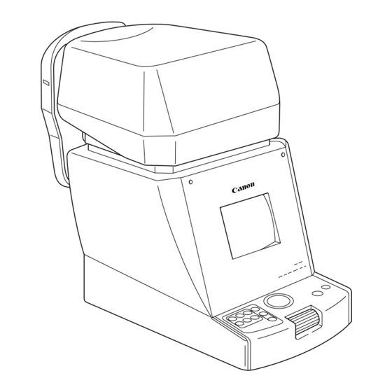
3. Description 3.1 Main Unit 1 Measurement Head 4 Brightness Adjuster Unit that performs measurement. Adjusts brightness of monitor. 2 Height Adjustment Mark 5 Monitor Align the height of the examinee’s eye with this Monitor that displays the screen for measure- mark by adjusting the height of chin rest. - Page 16 3.1 Main Unit 7 Face Rest 11 Forehead Rest Place the examinee’s face against this rest. Place the examinee’s forehead against this rest. 8 Printer 12 Measurement Window Prints measurements. Window for the examinee to look into for measurement. 9 Rating Plate 13 Chin Rest Name of the product, rated voltage, serial Place the examinee’s chin on this rest.
-
Page 17: Connectors Under The Main Unit
3.2 Connectors under the Main Unit 3.2 Connectors under the Main Unit NOTE: Do not remove the cover for the RS232C connector. Please contact Canon representative or distributor when connecting any instrument to the R-F10. 1 Power Supply Connector 2 RS232C Connector Connector for the power supply cable. -
Page 18: Operation Panel
3.3 Operation Panel 3.3 Operation Panel 1 DISP Switch 5 Trackball Press this switch in order to enter DISPLAY Moves the measurement head up and down, mode, where you can see measurement data right and left. stored in memory. 2 IOL Switch 6 START Switch Press this switch when the examinee’s eye is When this switch is pressed in automatic... - Page 19 3.3 Operation Panel 9 10 11 8 SET Switch 11 AUTO Switch Press this switch in order to enter SET mode, Press this switch in order to perform fully where you can perform various settings con- automatic measurement. cerning measurements. 9 MANU.
- Page 20 3.3 Operation Panel In DISPLAY and SET modes, a diagram showing the switches and their functions for the operation will be displayed on the lower part of the monitor, because the functions differ from that seen in the display of the switches. The diagram corresponds to the switches on the operation panel as follows: DISP switch VD switch...
-
Page 21: Measurements
When any operation has been interrupted for more than 3 minutes with the power turned ON, power-saving system of the R-F10 operates. Buzzer sounds when the instrument is entering or going out of this mode, and READY lamp blinks while this system is operat- ing. - Page 22 4.1 Preparation When the checks are completed, PD: – – VD:13.5 No. 00001 FULL AUTO mode will be selected FULL AUTO(3) and the measurement head will move and stop at the right eye side. NOTE: Because the measurement head moves during initializa- tion, do not have the examinee place his/her face on the chin RIGHT...
- Page 23 4.1 Preparation Adjust the height of the examinee’s eye . t s . t r t u l , t i t l u s i l f i c , l o t l u i l a , t s .
-
Page 24: Measurement In Full Auto Mode
4.2 Measurement in FULL AUTO Mode 4.2 Measurement in FULL AUTO Mode There are two modes of performing measurement; FULL AUTO and MANUAL. FULL AUTO mode is selected automatically when the power is turned ON or when the switch is pressed. PRINT The examiner can also choose FULL AUTO mode with the AUTO... - Page 25 4.2 Measurement in FULL AUTO Mode Check that automatic measurement has been chosen If the words “ ” is not FULL AUTO PD: – – VD:13.5 No. 00001 displayed on the monitor, press AUTO FULL AUTO(3) switch. RIGHT Check that the examinee’s eye is displayed on the monitor If you cannot see it at all, adjust the PD: –...
- Page 26 4.2 Measurement in FULL AUTO Mode Start automatic measurement Press the switch. START PD: – – VD:13.5 No. 00001 Measurement head moves automati- FULL AUTO(3) cally to perform alignment. Corneal bright dots RIGHT When a warning message “[1] EYE CANNOT BE FOUND PRESS START SW AGAIN”...
- Page 27 4.2 Measurement in FULL AUTO Mode – Continuous manual measurement – When START switch is pressed for about two seconds after the message is displayed, continuous measurements will start. Perform alignment manually using the roller and trackball after the measurement is started, referring to section 4.3. Measurement will be performed until 10 measurements are obtained.
- Page 28 4.2 Measurement in FULL AUTO Mode After the alignment, measurement is performed automatically Measurement is performed as many times as selected in the SET mode (→ section 6.1). PD: – – VD:13.5 No. 00001 FULL AUTO (3) RIGHT -0.37 -0.75 Sphere, cylinder, axis -0.50 -0.75...
- Page 29 4.2 Measurement in FULL AUTO Mode Move measurement head toward the other eye If “ ” is set to “ ” in SET mode (→ section 6.1), the measurement R–L MEASURE head automatically moves to the other eye. If the setting is “ ”, press the switch.
- Page 30 4.2 Measurement in FULL AUTO Mode Example of Printout CANON R-F10 Date and time 04/NOV/2002 14:25 Serial number No. 00001 NAME Space for name Vertex distance Right side eye <RIGHT> VD:13.5 –0.37 –0.75 Sphere, cylinder, axis Results of refractometry –0.50 –0.75...
-
Page 31: Measurement In Manual Mode
4.3 Measurement in MANUAL Mode 4.3 Measurement in MANUAL Mode Perform measurement in MANUAL mode when the pupil is eccentric, or when measuring a certain examinee is apt to result in error. NOTE: Be sure to perform focusing precisely in manual measurement. Otherwise, measure- ment error may occur. - Page 32 4.3 Measurement in MANUAL Mode Check that the alignment ring is not covered by eyelashes Looking at the monitor, check that the inner alignment ring (see the illustration in step 5 below) is not covered by eyelashes. If they are covering the ring, instruct the exam- inee to keep his/her eye opened wide until measurement ends, or help them open the eye wider by lifting up his/her upper eyelid lightly with your fingers.
- Page 33 4.3 Measurement in MANUAL Mode Perform focusing l u f t t i . t n Turn the roller back and forth to position the three bright dots vertically between the vertical alignment marks. Alignment mark Three bright dots must be aligned vertically.
- Page 34 4.3 Measurement in MANUAL Mode Measure the other eye Press the switch to move the PD: 67 VD:13.5 No. 00001 MANUAL measurement head to the other side. Measure the left eye in the same way as measuring the right eye. LEFT -0.62 0.00...
-
Page 35: Measurements Stored In Memory [Display Mode]
5. Measurements Stored in Memory [DISPLAY Mode] In DISPLAY mode, you can see the results (maximum of 10 data for each eye) of measure- ments stored in memory. Press switch in order to enter DISPLAY mode. DISP Press it again to go out. –... -
Page 36: Various Settings [Set Mode]
• Page 1/3: Display to set items concerning measurement. • Page 2/3: Display to set items concerning printing and transfer. • Page 3/3: Display to enter message to be printed with the R-F10 printer. Settings are stored and remain even after power is turned OFF. -
Page 37: Settings For Measurement (Page: 1/3)
6.1 Settings for Measurement (Page: 1/3) 6.1 Settings for Measurement (Page: 1/3) – SET MODE – PAGE: 1/3 12.0 13.5 – +/– 0.12 0.25 COUNT [No.] = 00001 RESET DATE 25/SEP/2001 14:50 ORDER AUTO MEASURE R–L MEASURE AUTO PRINT ← →... - Page 38 6.1 Settings for Measurement (Page: 1/3) Increment of sphere and cylinder “ ” 0.12 0.25 COUNT Whether to display and print the serial number “ ”: Serial number will be displayed on the monitor and printed with the result. It counts up at the measurement after the print.
- Page 39 6.1 Settings for Measurement (Page: 1/3) “ ”: Only one eye will be measured. When this is selected, printing must be done by pressing the PRINT switch. When you change the setting from “ ” to “ ” when “ AUTO PRINT ”...
-
Page 40: Settings For Printing And Transfer (Page: 2/3)
6.2 Settings for Printing and Transfer (Page: 2/3) 6.2 Settings for Printing and Transfer (Page: 2/3) – SET MODE – PAGE: 2/3 PRINT [FMT] AUTO [MSG] [EYE] [ECO] TRANS [FMT] [BAU] 9600.8N1 CHARACTER: LATIN-1 → ← – – – – – – –... -
Page 41: Items
6.2 Settings for Printing and Transfer (Page: 2/3) 6.2.2 Items PRINT Whether to print the result “ ”: Results are printed with the internal printer of the R-F10. “ ”: Not printed. [FMT] Results of refractometry to be printed out. Regardless of whether “... - Page 42 6.2 Settings for Printing and Transfer (Page: 2/3) [FMT] Transfer format NOTE: For details concerning format, please contact Canon representative or distributor. [How to change the setting] Press either switch or switch. START PRINT [BAU] RS232C data transfer speed and data format 9600.8N1...
-
Page 43: Entering Message For Internal Printer (Page: 3/3)
6.3 Entering Message for Internal Printer (Page: 3/3) 6.3 Entering Message for Internal Printer (Page: 3/3) Enter a message to be printed out with the result of measurement with the internal printer in this display. You can enter messages in 18 characters × 4 lines. Message is backed up by battery, and will be retained even if power is turned OFF. -
Page 44: How To Enter The Characters
6.3 Entering Message for Internal Printer (Page: 3/3) 6.3.2 How to Enter the Characters Move the position cursor to the required position Press switch or switch. Select the required character Press switch to select the line that includes the required character. Then, turn PRINT the roller to select the character. -
Page 45: How To Delete
6.3 Entering Message for Internal Printer (Page: 3/3) 6.3.4 How to Delete In order to delete single character and shift all the characters on the right-hand side to the left side by one space Move the position cursor to the character to be deleted Press switch or switch. - Page 46 6.3 Entering Message for Internal Printer (Page: 3/3) Select the line “CHAR CLEAR / LINE CLEAR / ALL CLEAR” Press switch. PRINT Select “LINE CLEAR” Turn the roller until “ ” is displayed in reverse image LINE CLEAR Delete the line Press switch.
-
Page 47: Daily Inspection And Maintenance
In order to ensure that the instrument is used safely and normally, please be sure to inspect the instrument before use. If any problem is found during the inspection, please take measures indicated in this chapter. If problem still cannot be corrected, please contact Canon representative or distributor. f i l . y l... -
Page 48: Before Turning On The Power
7.1 Inspection 7.1.1 Before Turning ON the Power c t i o l l t l u y l l t e l s t i t e l . h t , y t t s i t a l u l i t l u r i f... -
Page 49: After Turning On The Power
7.1 Inspection 7.1.2 After Turning ON the Power t l u g i l t i n . l a c t i t i n l l a l l o – 37 –... -
Page 50: Before Calling A Service Person
Whenever a problem occurs or message appears on the monitor, take the countermeasures indicated below according to the cause. If function is still not restored, contact Canon representative or distributor. 7.2.1 If Problems Such as Following Occur d i l... -
Page 51: If Message Such As Following Appears On The Monitor
7.2.2 If Message Such as Following Appears on the Monitor If message does not disappear even after taking the countermeasures indicated in this sec- tion, contact Canon representative or distributor. In this case, please let us know the message that is displayed. - Page 52 7.2 Before Calling a Service Person g i l e l l c t i c t i l l a e l l c i t g i l i l l y l r t i s g i l .
- Page 53 7.2 Before Calling a Service Person e l l c t i l l a e l l c t i s i t . e l n i l . e l i t c . y t . e l i t c .
- Page 54 7.2 Before Calling a Service Person t n i l l o t n i t n i t n i . n i t n i t n i . d l - - - - - - . t n e l l c t i .
-
Page 55: Cleaning And Disinfection
Wipe the protective glass lightly with sterile gauze or non treated lens paper, on which you can put some lens cleaner. Please consult Canon repre- sentative or distributor about lens cleaners that can be used. Change the paper and wipe the lens several times until there is no lens cleaner left on the surface. -
Page 56: Forehead Rest
7.3 Cleaning and Disinfection 7.3.2 Forehead Rest t u l , t i s i l f i c , l o t l u i l a , t s . t s 7.3.3 Cover, Monitor and Roller Clean the cover and monitor if they are dirty. c t i e l t , l o... -
Page 57: Trackball
7.3 Cleaning and Disinfection 7.3.4 Trackball Clean the trackball if it does not rotate smoothly. (1) Turn the trackball cover in counter- clockwise direction to remove it. NOTE: Trackball cover will be re- moved with the trackball. Be careful not to hit or drop the Trackball cover trackball cover when the trackball is attached to it, as... -
Page 58: Replacement
7.4 Replacement 7.4 Replacement Please refer to “7.5 Expendable Parts List” for ordering chin rest paper and printing paper. 7.4.1 Chin Rest Paper NOTE: When chin rest paper is not going to be used, disinfect the chin rest in the same ways as disinfecting the forehead rest each time the examinee changes. -
Page 59: Printing Paper
7.4 Replacement 7.4.2 Printing Paper Replace the roll of printing paper as soon as possible after the red line appears on the paper. Open the printer cover Cut off the paper that has been fed through the printer and pull it out. Pull the top part toward you. - Page 60 Raise the lever Turn ON the power Turn ON the power of the R-F10. Insert the end of paper into the slot Insert the end of paper into the slot in the printer.
-
Page 61: Expendable Parts List
Pull out the edge of paper from the printer cover slot and close the cover. 7.5 Expendable Parts List Please contact Canon representative or distributor for purchasing the following parts: t n i s l l : h t : h t... -
Page 62: Installation
NOTES: 1. The measurement head is positioned at the center when the instrument is shipped from Canon. However, if it is positioned either on the right or left side, lay the instrument on the side opposite the side from which the measurement head is protruding. - Page 63 → Section 7.4.2 Customize the settings as required Change the order of measurement modes and the settings concerning the measurement as required (→ chapter 6). If you are using external equipment Please contact Canon representative or distributor. – 51 –...
-
Page 64: Precautions When Moving The Instrument
NOTE: When the instrument is going to be transported by automobile, etc., it must be protected against vibration and shocks. Contact Canon representative or distribu- tor for advice on the procedure for packing it. Move the measurement head to the center Turn ON the power while pressing the switch. -
Page 65: Service Information
Repair If problem cannot be solved even after taking the measures indicated in sections 7.1 and 7.2, contact Canon representative or distributor for repair. Please refer to the rating plate and let us have the following information: Name of the instrument: R-F10 Body number: 6-digit number indicated on the rating plate. -
Page 66: Specifications
10. Specifications Purpose: Measurement of refractive power of human Measurement: Vertex distance 0, 12, 13.5 mm Measurable range Sphere power -30.00 to +22.00 D (at vertex distance of 12 mm) (Increments selectable between 0.12 and 0.25 D) Cylinder power 0.00 to ±10.00 D (Increments selectable between 0.12 and 0.25 D) Axis 1 to 180°... -
Page 67: Components
11. Components R-F10 main unit ............1 Power supply cable ............1 Chin rest paper ............. 100 sheets Printing paper ............... 2 rolls Dust cover ..............1 Blower brush ..............1 Optional Accessories Chin rest paper (500 sheets) Printing paper (10 rolls) Motorized table CO-MT –... - Page 68 This page has been left intentionally blank. – 56 –...
- Page 69 Blank Page...
- Page 70 CANON INC. Medical Equipment Group 20-2 Kiyohara-Kogyodanchi, Utsunomiyashi, Tochigiken, Japan Telephone: (81)-28-667-5711 CANON MEDICAL SYSTEMS Eye Care Systems Department 15955 Alton Parkway, Irvine, CA 92618, U.S.A. Telephone: (1)-949-753-4162 CANON EUROPA N.V. Medical Products Division Bovenkerkerweg 59-61, P. O. Box 2262, 1180 EG Amstelveen, The Netherlands Telephone: (31)-20-545-8926 CANON SINGAPORE PTE.