Table of Contents
Advertisement
Advertisement
Table of Contents

Related Manuals for GE Profile PTDS650EM


Summary of Contents for GE Profile PTDS650EM
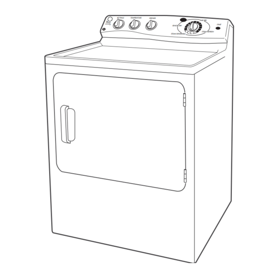
- Page 1 GE Appliances Technical Service Guide December 2010 Profi le Stainless Steel Drum Gas and Electric Dryers with Steam SETTINGS TEMPERATURE DRYNESS TIME DRY START SENSOR DRY STEAM REFRESH STEAM DEWRINKLE PTDS650EM PTDS650GM 31-9205 GE Appliances General Electric Company Louisville, Kentucky 40225...
- Page 2 If grounding wires, screws, straps, clips, nuts, or washers used to complete a path to ground are removed for service, they must be returned to their original position and properly fastened. GE Appliances Technical Service Guide Copyright © 2010 All rights reserved. This service guide may not be reproduced in whole or in part in any form without written permission from the Gen er al Electric Com pa ny.
-
Page 3: Table Of Contents
Table of Contents Air Duct Assembly ................................21 Airfl ow ....................................14 Blower Wheel ..................................28 Burner Assembly and LP Conversion ........................31 Component Locator Views ............................16 Control Board Connector Locator View .........................18 Control Features ................................7 Control Panel..................................19 Cycle Matrix Chart ................................15 Door Switch ..................................22 Drive Belt ....................................24 Drum .......................................25 Drum Light Receptacle ..............................22... -
Page 4: Introduction
Introduction Steam and SensorDry Plus™ Features • Antibacterial cycle - Reduces certain types of bacteria by 99.9% Profi le 650 model dryers now incorporate two new steam features. These units do not utilize a separate • Delicate cycle with low-heat setting - Low- steam generator. -
Page 5: Nomenclature
Nomenclature P T D S 6 5 0 E L W W Color Brand Series WW = White P = Profi le BB = Black D = General Electric MV = Metallic Red MG = Metallic Gold Confi guration MS = Metallic Block T = Top Load F = Front Load Model Year Designator... -
Page 6: Water Line Connection
Water Line Connection WATER SUPPLY REQUIREMENTS 4. Insert the fi lter screen in the coupling of the washer’s inlet hose. If a rubber fl at washer is Hot and cold water faucets MUST be installed within already in place remove it before installing the 42 in. -
Page 7: Control Features
Control Features About the control panel GEAppliances.com Step 1 Step 2 Step 3 Step 4 • Select Dry Cycle • Shut door • Clean lint filter • Add clothes • Push START Quick Start Guide Note: When making a selection with any knob, simply point the knob anywhere within the shaded range for NOTE: When making a selection with any knob, simply point the knob anywhere within the shaded range that setting. - Page 8 About the control settings. End of Cycle Signal This signal will sound just before the end of the cycle to remind you to remove the clothes. If you select the EXTENDED TUMBLE option, the signal will sound at the end of the drying time and will sound several times during the EXTENDED TUMBLE cycle.
- Page 9 About the control settings. Estimated Time Remaining Display • Displays the approximate time remaining until the end of the cycle. • If the estimated time remaining is 60 minutes or more, “1H” will flash in the display, followed by the additional remaining minutes.
- Page 10 About the control settings. STEAM REFRESH For slightly wrinkled dry garments. Significantly reduces wrinkles. After the STEAM REFRESH ( on some models) Cycle, the unit will beep (if Signal is selected) and display “00.” Steam Refresh Large is recommended for 3-5 garments and Small for 1-2 garments. NOTE: Steam cycles are not intended for use with towels.
-
Page 11: Dryer Features
These dryer drum provides the highest reliability surface blemishes will not affect the function available in a GE dryer. If the dryer drum or durability of the drum. should be scratched or dented during normal... -
Page 12: Reversing The Door
Reversing the Door Reversing the Door Tools needed: Standard #2 Tape-tipped Phillips screwdriver putty knife Open the door and remove the filler plugs opposite the hinges. With the door completely open, remove the bottom screw from each hinge on the dryer face. Insert these screws about half way into the TOP holes, for each hinge, on the opposite side (where you removed the filler plugs). -
Page 13: Operation Overview
Operation Overview Air enters the dryer cabinet, passing thru the heating elements and into the drum. The hot air heats the wet clothes and gradually removes their moisture in the form of water vapor. The moist air is vented through the dryer exhaust. -
Page 14: Airfl Ow
Airfl ow – 14 –... -
Page 15: Cycle Matrix Chart
Cycle Matrix Chart Steam De-wrinkle Extended Tumble Tumble Water Tumble Water Tumble Water Tumble Tumble with with Valve on with Valve on with Valve on with Cool Water Valve on and (if option heat heat Heat off heat Heat off heat Heat off heat... -
Page 16: Component Locator Views
Component Locator Views Electric Model Control Panel Inlet Control Thermistor Inlet Safety Thermostat High Limit Thermostat Heater Assembly Water Valve (inside cover) Idler Pulley Motor (under shield) Outlet Control Backup Thermostat (under shield) Blower Wheel Outlet Control Thermistor (behind frame) (Continued Next Page) –... - Page 17 Gas Model Control Panel High Limit Thermostat Inlet Safety Thermostat Inlet Control Thermistor Water Valve (inside cover) Idler Pulley Motor (under shield) Outlet Control Backup Thermostat (under shield) Burner Assembly Blower Wheel Outlet Control Thermistor (behind frame) – 17 –...
-
Page 18: Control Board Connector Locator View
Control Board Connector Locator View Electronic Control - Rear View (Electric and Gas Models) J3 - Model Selector J5 - L1 and Neutral Supply to Control Board, Door State Signal, Water Valve, Motor J10 - Moisture Sensor Rods, Outlet Control Thermistor, Inlet Control Thermistor J21 - Water Valve Relay U4 - Outer Coil (Electric Heat), Gas Valve (Gas Heat) U9 - Outer Coil L1 (Electric Heat), Line (Gas Heat) -
Page 19: Control Panel
Dryer Components WARNING: Sharp edges may be exposed when 3. Rotate the control panel forward approximately servicing the dryer. Use caution to avoid injury. 1 inch, then slide it to the right to unlock the 3 Wear Kevlar gloves or equivalent protection. bottom lock tabs. -
Page 20: Drum Slide Assembly
Front Panel Drum Slide Assembly The front panel is fastened to the cabinet at the The drum slide assembly is located on the back inside front by 2 screws and at the bottom by 3 tabs side of the front panel and utilizes 4 drum slides. protruding from the base of the cabinet. -
Page 21: Air Duct Assembly
Air Duct Assembly Steam Nozzle The air duct assembly houses the drum seal, steam The steam nozzle is located inside the front of the nozzle, and the 2 sensor rods. It is located on the dryer on the right side of the air duct assembly. The back side of the front panel. -
Page 22: Door Switch
To replace the steam nozzle connector: Door Switch 1. Remove the air duct assembly. The door switch is fastened to the front panel by 2 locking tabs (1 on each side). When the dryer door 2. Press on the John Guest connector collar and is closed, the switch will complete the drum motor release the water line from the steam nozzle circuit, allowing dryer operation. -
Page 23: Moisture Sensor
• Empty drum detection is not required for these Moisture Sensor models. The control shall run for the minimum dry time if no load is present. The moisture-sensing circuit consists of 2 sensor rods. They are mounted beneath the lint fi lter on the The dryer will signal when the clothes are at 17% drum side of the air duct. -
Page 24: Drive Belt
To install the drive belt: Drive Belt 1. Remove the top and front panels. (See Top Panel WARNING: Sharp edges may be exposed when and Front Panel servicing the dryer. Use caution to avoid injury and wear Kevlar gloves and sleeves or equivalent 2. -
Page 25: Drum
Drum Drum Shaft and Bearing The drum is made of 304 stainless steel and has The drum shaft is attached to the rear of the drum three replaceable baffl es. with three T-20 Torx screws. The bearing can be removed by pulling it off the shaft. The drum shaft To remove the drum: and bearing fi... -
Page 26: Idler Assembly
Idler Assembly Water Inlet Valve The idler assembly maintains proper tension on the The water inlet valve is located inside the cabinet belt to minimize belt slippage. The idler assembly at the bottom right hand corner. The water valve is consists of an idler pulley that rotates on an idler enclosed under a metal cover. - Page 27 4. Rotate the valve cover towards the front of the 6. Disconnect the coil wiring. cabinet until the inlet hose clears the back of 7. Press the John Guest connector collar and the cabinet. Then lift the assembly to clear the remove the water outlet tubing.
-
Page 28: Blower Wheel
Blower Wheel Motor The blower wheel is held to the motor shaft with The motor is a single-speed, dual-shaft, 1/4-hp, a 15/16-in. (24-mm) molded nut. To remove the 1725-rpm motor with an automatic reset overload blower wheel, it is not necessary to remove the protector. - Page 29 Note: In the following step, the motor moisture 9. Disconnect the motor wire harness. shield is attached to the motor bracket with a 10. Disconnect the wires attached to the belt switch. Phillips-head screw and 2 tabs that engage a slots in the motor bracket.
-
Page 30: Heater Assembly
Note: When installing the motor and blower wheel Heater Assembly assembly, ensure that the 2 rear tabs on the motor bracket are inserted into the slots in the motor The heater assembly is located behind the drum. support, and the 2 front tabs on the motor bracket It consists of inner and outer open-wire elements, are inserted into slots provided in the chassis. -
Page 31: Burner Assembly And Lp Conversion
To remove the double and main coils: Burner Assembly and LP Conversion 1. Remove the top panel, front panel, and drum. The burner assembly consists of the gas valve coils, (See Top Panel, Front Panel, and Drum gas valve, burner, and inlet pipe. 2. -
Page 32: Gas Valve
7. Disconnect the ignitor wire harness and the 2 Gas Valve wires from the fl ame detector. The gas valve is attached to a bracket located in the 8. Disconnect the coil wire harness from each coil. bottom, right, front corner of the dryer cabinet. 9. -
Page 33: Flame Detector
Ignitor Flame Detector The ignitor is located at the end of the burner The fl ame detector is attached to the right side of assembly in the combustion chamber opening and the combustion chamber. It is necessary to remove has a maximum rating of 4 amps. The ignitor has an the fl... -
Page 34: Ignitor Circuit Operation
Ignitor Circuit Operation The glo-bar ignitor circuit is made up of the following components: a gas valve with safety and main valves, ignitor, and a fl ame detector. The safety valve is actuated by a double coil that comprises a safety coil (resistance approximately 1350 ohms) and a booster coil (resistance approximately 550 ohms). -
Page 35: Inlet Control Thermistor
Inlet Safety Thermostat Inlet Control Thermistor On electric models, the inlet safety thermostat is On electric models, the inlet control thermistor is located on the top left area of the heater housing, located on the top left area of the heater housing, to the left of the inlet control thermistor. -
Page 36: Outlet Control Thermistor
Operation of the inlet control thermistor can be Outlet Control Thermistor checked by using service test mode t7. (See Service Test Mode The outlet control thermistor is located on the lower rear area of the blower housing. It is below Specifi... -
Page 37: High Limit Thermostat
Outlet Control Backup Thermostat High Limit Thermostat The outlet control backup thermostat is located On electric models, the high limit thermostat is on the upper, rear area of the blower housing. It located on the top right area of the heater housing. is below the moisture shield and above the outlet On gas models, the high limit thermostat is located control thermistor. -
Page 38: Electronic Control
Temperarture Setpoints Electronic Control Heat Temperature Heat The electronic control consists of a selector board Source Setpoint Setting Setpoint and a control board. Both boards are connected to Extra Low 104°F each other with a ribbon. The boards are attached 121°F to the back of the control panel and control all dryer Outlet... -
Page 39: Service Test Mode
Troubleshooting Service Test Mode The dryer control has a service test mode that can be utilized by the service technician in order to test critical components and to access error codes. This test mode will help the service technician to quickly identify failed or improperly operating dryer components. - Page 40 Service Test Mode Sequence Enter door open/closed test. "do" means door open. "dc" START/PAUSE Door Open/ means door closed. Closed KNOB Select next service mode test. Enter brownout signal test. “EP” will be displayed if brownout START/PAUSE Brownout circuit is working correctly and input voltage is greater than Signal 90 VAC.
- Page 41 General Troubleshooting Guide - Electric Model COMPLAINT WRINKLES NO HEAT SHRINKAGE LONG DAY ALL FABRICS DAMAGE DAMAGE TIME ALL LOADS NO HEAT LONG DRY TIME CHECK SHAGS CUTS CHECK ALL DRUM & THERMOSTATE INTERIOR SURFACES CHECK 240 V TEMPERATURE BOTH SUPPLY DRUM CAP DRUM SPEED CHECK ARE...
- Page 42 General Troubleshooting Guide - Gas Model COMPLAINT WRINKLES SHRINKAGE DAMAGE NO HEAT LONG DRY TIME ALL FABRICS SYNTHETICS CLOTHES WET ALL LOADS ONLY SHORT BURN CYCLE NO HEAT, SHORT BURN LONG DRY TIME DAMAGE THERMOSTAT TEMPERATURE GENERAL CARE IGNITER DRUM SPEED LABEL WASH AND DRUM &...
-
Page 43: Schematics And Wiring Diagrams
Schematics and Wiring Diagrams Electric Model – 43 –... - Page 44 Gas Model – 44 –...
-
Page 45: Warranty
This warranty is extended to the original purchaser and any succeeding owner for products purchased for home use within the USA. If the product is located in an area where service by a GE Authorized Servicer is not available, you may be responsible for a trip charge or you may be required to bring the product to an Authorized GE Service location for service.