Husqvarna 1365GN Owner's Manual
Husqvarna portable generator owner's manual
Hide thumbs
Also See for 1365GN:
- Operator's manual (36 pages) ,
- Owner's manual (40 pages) ,
- Operator's manual (44 pages)

Related Manuals for Husqvarna 1365GN


Summary of Contents for Husqvarna 1365GN
- Page 1 01935 1365GN Owner’s Manual Read this manual carefully and become familiar with your generator. Know the applications, the limitations and any hazards involved. [193174GS Rev 0a (06/01/04)] Part Number 531 30 00-69...
-
Page 2: Table Of Contents
TABLE OF CONTENTS Safety Rules........2-4 Know Your Generator ......5 Assembly. -
Page 3: Safety Rules
DANGER Running generator gives off carbon monoxide, an odorless, colorless, poison gas. Breathing carbon monoxide will cause nausea, fainting or death. • Operate generator ONLY outdoors. • Keep at least 2 feet of clearance on all sides of generator for adequate ventilation. -
Page 4: Safety Rules
Improper treatment of generator can damage it and shorten its life. • Use generator only for intended uses. • If you have questions about intended use, ask your Husqvarna dealer or contact customer service at 1-877-224-0458. • Operate generator only on level surfaces. -
Page 5: Know Your Generator
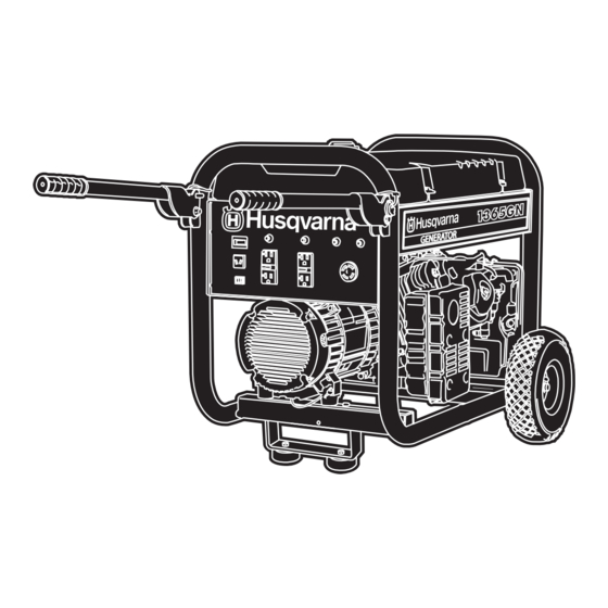
KNOW YOUR GENERATOR Read this owner’s manual and safety rules before operating your generator. Compare the illustrations with your generator, to familiarize yourself with the locations of various controls and adjustments. Save this manual for future reference. Oil Fill Fuel Tank Hour Meter 12 Volt DC,10 Amp Receptacle... -
Page 6: Assembly
ASSEMBLY Your generator requires some assembly and is ready for use after it has been properly serviced with the recommended oil and fuel. If you have any problems with the assembly of your generator, please call the generator helpline at 1–877–224–0458. -
Page 7: Assembly
Slide axle through both axle mounting brackets on cradle frame, as shown in Figure 1. Slide a wheel over the axle. NOTE: Be sure to install both wheels with the air pressure valve on the outboard side. Place the e-ring onto the groove in the axle.You may add the flat washer if desired. - Page 8 GROUNDING THE GENERATOR The National Electrical Code requires that the frame and external electrically conductive parts of this generator be properly connected to an approved earth ground. Local electrical codes may also require proper grounding of the unit. For that purpose, a GROUNDING FASTENER is provided on the generator end (Figure 2).
-
Page 9: Charging A Battery
Start engine according to instructions given in engine owner’s manual. NOTE: If engine starts after 3 pulls but fails to run, or if unit shuts down during operation, make sure unit is on a level surface and check for proper oil level in crankcase. This unit may be equipped with a low oil protection device. -
Page 10: Operation
Connect battery charge cable clamp with black handle to the negative (–) battery terminal (Figure 5). Start engine. Let engine run while battery recharges. When battery has charged, shut down engine NOTE: Use an automotive hydrometer to test battery state of charge and condition. Follow the hydrometer manufacturer’s instructions carefully. - Page 11 RECEPTACLES CAUTION Receptacles may be marked with rating value greater than generator output capacity. • NEVER attempt to power a device requiring more amperage than generator or receptacle can supply. • DO NOT overload the generator. See “Don’t Overload Generator”. 120/240 Volt AC, 30 Amp, Locking Receptacle Use a NEMA L14–30 plug with this receptacle.
-
Page 12: Ground Fault Protection
Ground Fault Protection This unit is equipped with a Ground Fault Circuit Interrupter (GFCI).This device meets applicable federal, state and local codes. The GFCI protects against electrical shock that may be caused if your body becomes a path which electricity travels to reach the ground.This could happen if you touch a “Live”... - Page 13 DON'T OVERLOAD GENERATOR Capacity You must make sure your generator can supply enough rated (running) and surge (starting) watts for the items you will power at the same time. Follow these simple steps: Select the items you will power at the same time. Total the rated (running) watts of these items.This is the amount of power your generator must produce to keep your items running.
-
Page 14: Maintenance
SPECIFICATIONS Maximum Surge Watts ....8,125 watts Continuous Wattage Capacity ...6,500 watts Power Factor ......1.0 Rated Maximum Continuous AC Load Current: At 120 Volts . -
Page 15: Storage
STORAGE The generator should be started at least once every seven days and allowed to run at least 30 minutes. If this cannot be done and you must store the unit for more than 30 days, use the following guidelines to prepare it for storage. -
Page 16: Notes
Notes NOTES... -
Page 17: Troubleshooting
TROUBLESHOOTING Problem Engine is running, but no AC output is available. Engine runs good but bogs down when loads are connected. Engine shuts down during operation. Engine lacks power. Troubleshooting Cause Circuit breaker is open. Poor connection or defective cord set. Connected device is bad. - Page 18 Schematic SCHEMATIC...
-
Page 19: Schematic/ Wiring Diagram
Wiring Diagram WIRING DIAGRAM... - Page 20 Exploded Views EXPLODED VIEW – MAIN UNIT...
-
Page 21: Exploded Views
PARTS LIST – MAIN UNIT Item Part # Description N192958AGS CRADLE 82857GS MOUNT,Vibration N92531GS SUPPORT, Engine 190220GS HOUSING, Engine Adapter 45771GS ASSY, Alternator (see page 22) N92731GS SUPPORT, Eng/Muffler 96796GS WASHER 92609GS MOUNT,Vibration 10 190274BGS SCREW 11 187365JGS SCREW 12 189160GS 13 22142GS SCREW 14 193048GS... - Page 22 EXPLODED VIEW AND PARTS LIST – ALTERNATOR Item Part # 186059GS 192919GS 192920AGS 193336GS 86308HGS 66386GS 66849GS 22694GS 81917GS 10 191051AGS 12 23762GS 13 192403XGS 14 189769GS 15 65795GS 16 66849AGS Exploded Views Description ADAPTER, Mounting, Alternator ROTOR STATOR RBC, (with O-Ring, p/n 189197GS) SCREW ASSY, Holder, Brush SCREW...
- Page 23 EXPLODED VIEW AND PARTS LIST – CONTROL PANEL Item Part # Description PANEL, Control B192836GS BOX, Control Panel 23897GS WASHER 49226GS WASHER, Lock 91526GS SCREW 22447GS WASHER 82538GS SWITCH, Rocker 90418GS OUTLET, 12VDC, Snap 77604GS METER, Hour 10 43182GS WASHER, Lock 11 51714GS 12 43181GS SCREW...
- Page 24 EXPLODED VIEW AND PARTS LIST – WHEEL KIT Item Part # 22247GS B4966GS 191267KGS 191265GS 39253GS B89595GS 87841GS 22287GS 67989GS 10 B2071GS 11 B4605GS 12 B187113GS 13 39287GS 14 22145GS 15 49820GS 16 187104GS 17 B4135GS Exploded Views Description WASHER WHEEL AXLE E-RING...
-
Page 25: Warranty
“Briggs & Stratton Power Products will repair or replace, free of charge, any part or parts of this Husqvarna® branded product** that are defective in material or workmanship or both.Transportation charges on parts submitted for repair or replacement under this warranty must be borne by purchaser.This warranty is effective for the time periods and subject to the conditions stated below.