Table of Contents
Advertisement
INSTALLER: LEAVE THIS MANUAL WITH THE APPLIANCE.
CONSUMER: RETAIN THIS MANUAL FOR FUTURE REFERENCE.
CERTIFIED UNDER CANADIAN AND AMERICAN NATIONAL STANDARDS, CR97-003, CAN1-2.21-M85, IAS U.S. 4-96.
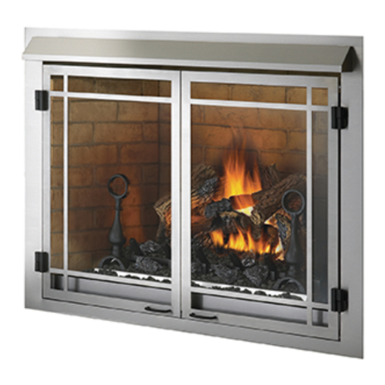
OUTDOOR GAS FIREPLACE
GSS42N
NATURAL GAS MODEL
GSS42P
PROPANE GAS MODEL
CERTIFIED FOR CANADA AND UNITED STATES USING ANSI/CSA METHODS.
SAFETY INFORMATION
WARNING
!
If the information in these instructions are
not followed exactly, a fi re or explosion
may result causing property damage,
personal injury or loss of life.
- Do not store or use gasoline or other fl ammable
vapors and liquids in the vicinity of this or any
other appliance.
- WHAT TO DO IF YOU SMELL GAS:
•
Do not try to light any appliance.
•
Do not touch any electrical switch; do not use
any phone in your building.
•
Immediately call your gas supplier from a
neighbour's phone. Follow the gas supplier's
instructions.
•
If you cannot reach your gas supplier, call the
fi re department.
- Installation and service must be performed by a
qualifi ed installer, service agency or the supplier.
Phone (705)721-1212 • Fax (705)722-6031 • www.napoleonfi replaces.com • ask@napoleonproducts.com
$10.00
OPERATING INSTRUCTIONS
Wolf Steel Ltd., 24 Napoleon Rd., Barrie, ON, L4M 0G8 Canada /
103 Miller Drive, Crittenden, Kentucky, USA, 41030
INSTALLATION AND
WARNING: FOR OUTDOOR USE ONLY
WARNING
!
HOT GLASS WILL CAUSE
BURNS.
DO NOT TOUCH GLASS UNTIL
COOLED.
NEVER ALLOW CHILDREN TO
TOUCH GLASS.
1.22A
W415-0617 / D / 03.18.11
1
Advertisement
Table of Contents

Related Manuals for Napoleon GSS42N


Summary of Contents for Napoleon GSS42N
-
Page 1: Safety Information
CONSUMER: RETAIN THIS MANUAL FOR FUTURE REFERENCE. INSTALLATION AND OPERATING INSTRUCTIONS CERTIFIED UNDER CANADIAN AND AMERICAN NATIONAL STANDARDS, CR97-003, CAN1-2.21-M85, IAS U.S. 4-96. OUTDOOR GAS FIREPLACE GSS42N NATURAL GAS MODEL GSS42P PROPANE GAS MODEL CERTIFIED FOR CANADA AND UNITED STATES USING ANSI/CSA METHODS. -
Page 2: Table Of Contents
TABLE OF CONTENTS INSTALLATION OVERVIEW INTRODUCTION DIMENSIONS GENERAL INSTRUCTIONS GENERAL INFORMATION RATING PLATE INFORMATION INSTALLATION GAS INSTALLATION GAS INLET LOCATIONS OPTIONAL WALL SWITCH INSTALLATION COMBUSTION AND VENTILATION AIR FRAMING CLEARANCE TO COMBUSTIBLES MINIMUM ENCLOSURE CLEARANCES MINIMUM MANTEL CLEARANCES NAILING TAB FINISHING ANDIRON AND GRATE ASSEMBLY LOG PLACEMENT... -
Page 3: Introduction
2.0 INTRODUCTION WARNING • THIS APPLIANCE IS HOT WHEN OPERATED AND CAN CAUSE SEVERE BURNS IF CONTACTED. • Do not operate appliance before reading and understanding operating instructions. Failure to operate appliance according to operating instructions could cause fi re or injury. •... -
Page 4: Dimensions
DIMENSIONS ” ” ” ” ” GENERAL INSTRUCTIONS WARNING ALWAYS LIGHT THE PILOT WHETHER FOR THE FIRST TIME OR IF THE GAS SUPPLY HAS RAN OUT, WITH THE GLASS DOOR OPENED OR REMOVED. NEVER OBSTRUCT THE FRONT OPENING OF THE APPLIANCE. OBJECTS PLACED IN FRONT OF THE APPLIANCE MUST BE KEPT A MINIMUM OF 48”... -
Page 5: General Information
The appliance and its individual shutoff valve must be disconnected from the gas supply piping system during any pressure testing of that system at test pressures in excess of 1/2 psig (3.5 kPa). The appliance must be isolated from the gas supply piping system by closing its individual manual shutoff valve during any pressure testing of the gas supply piping system at test pressures equal to or less than 1/2 psig (3.5 kPa). -
Page 6: Installation
3.0 INSTALLATION GAS INSTALLATION WARNING RISK OF FIRE, EXPLOSION OR ASPHYXIATION. ENSURE THERE ARE NO IGNITION SOURCES SUCH AS SPARKS OR OPEN FLAMES. SUPPORT GAS CONTROL WHEN ATTACHING GAS SUPPLY PIPE TO PREVENT DAMAGING GAS LINE. ALWAYS LIGHT THE PILOT WHETHER FOR THE FIRST TIME OR IF THE GAS SUPPLY HAS RUN OUT WITH THE GLASS DOOR OPENED OR REMOVED. -
Page 7: Gas Inlet Locations
GAS INLET LOCATIONS There are fi ve gas inlet locations on the ventless fi rebox enclosure. One on each side of the appliance, two at the rear, and one on the bottom. Using the following illustrations identify the preferred inlet and remove corresponding knock out. -
Page 8: Combustion And Ventilation Air
COMBUSTION AND VENTILATION AIR This appliance is intended for installation on an outdoor patio or in your yard. It must never be installed inside the warm air envelope of your structure. It is highly recommended that this appliance be installed in a “sheltered” area. Direct wind will cause an erratic fl... - Page 9 Minimum Clearance to Combustibles construction from appliance and vent surfaces: Framing 0” to stand-offs (rear and sides only) Use a steel header for the top and two steel studs on the sides. Finishing 1” to back and sides Non-combustible fi nishing 18”...
-
Page 10: Minimum Enclosure Clearances
WARNING USE ONLY NON-COMBUSTIBLE MATERIAL SUCH AS CEMENT BOARD, CERAMIC TILE, MARBLE, ETC. WHEN FINISHING TO THE APPLIANCE. DO NOT USE WOOD OR DRYWALL. *From top of unit. NON-COMBUSTIBLE ** An outdoor sealant must be used along the STEEL FINISHING MATERIAL edge of the fi... -
Page 11: Minimum Mantel Clearances
MINIMUM MANTEL CLEARANCES WARNING RISK OF FIRE, MAINTAIN ALL SPECIFIED AIR SPACE CLEARANCES TO COMBUSTIBLES. FAILURE TO COMPLY WITH THESE INSTRUCTIONS MAY CAUSE A FIRE OR CAUSE THE APPLIANCE TO OVERHEAT. ENSURE ALL CLEARANCES (I.E. BACK, SIDE, TOP, VENT, MANTEL, FRONT, ETC.) ARE CLEARLY MAINTAINED. -
Page 12: Finishing
5.0 FINISHING ANDIRON AND GRATE ASSEMBLY With the 2 andirons laying face down, secure the grate Use only accessories overtop using 2 of the 1” hex head screws (supplied in the designed for and listed manual baggie). with your specific log set. -
Page 13: Glowing Embers
Place the end of log #3 on the right side of Place locating pin in the end of log #4 into the the knot of log #1. The “Y” in the log should hole in log #2. Place the locating pin on the straddle the knot on top of log #2. -
Page 14: Hood
HOOD WARNING DO NOT OPERATE WITHOUT HOOD IN PLACE. THE APPLIANCE HOOD MUST NOT BE MODIFIED OR REPLACED WITH ANOTHER HOOD. NOTE: Remove the hood from the inside of the appliance by cutting the strap holding it in place. Line the 3 tabs on the back of the hood up with the 3 slots in the appliance front. -
Page 15: Optional Remote Installation
6.0 OPTIONAL REMOTE INSTALLATION REMOTE RECEIVER SLIDE SWITCH FACEPLATE VALVE JUNCTION REAR BURNER BASE Slide the junction box into the hole located at the rear of the burner base. Secure using two of the screws provided. Secure the faceplate to the junction box with two of the screws provided. Insert the remote receiver (with batteries installed) though the opening in the faceplate and into the junction box. -
Page 16: Operation
7.0 OPERATION WARNING IF YOU DO NOT FOLLOW THESE INSTRUCTIONS EXACTLY, A FIRE OR EXPLOSION MAY RESULT CAUSING PROPERTY DAMAGE, PERSONAL INJURY OR LOSS OF LIFE. When lit for the fi rst time, the appliance will emit an odor for a few hours. This is a normal temporary condition caused by the “burn-in”... -
Page 17: Adjustment
8.0 ADJUSTMENT VENTURI ADJUSTMENT WARNING CARBON CAN BE DISTRIBUTED IN SURROUNDING LIVING AREA IF THE AIR SHUTTER IS IMPROPERLY ADJUSTED. 49.5 This appliance has an air shutter that has been factory set open according to the chart below: VENTURI BURNER Regardless of venturi orientation, closing the air shutter will cause a more yellow flame, but can lead to carboning. -
Page 18: Maintenance
9.0 MAINTENANCE MAINTENANCE MAINTENANCE WARNING MAINTENANCE TURN OFF THE GAS AND ELECTRICAL POWER BEFORE SERVICING THE APPLIANCE. APPLIANCE MAY BE HOT, DO NOT SERVICE UNTIL APPLIANCE HAS COOLED. DO NOT USE ABRASIVE CLEANERS. CAUTION: Label all wires prior to disconnection when servicing controls. Wiring errors can cause improper and dangerous operation. -
Page 19: Replacements
10.0 REPLACEMENTS WARNING FAILURE TO POSITION THE PARTS IN ACCORDANCE WITH THIS MANUAL OR FAILURE TO USE ONLY PARTS SPECIFICALLY APPROVED WITH THIS APPLIANCE MAY RESULT IN PROPERTY DAMAGE OR PERSONAL INJURY. ** THIS IS A FAST ACTING THERMOCOUPLE. IT IS AN INTEGRAL SAFETY COMPONENT. REPLACE ONLY WITH A FAST ACTING THERMOCOUPLE SUPPLIED BY WOLF STEEL LTD. - Page 20 COMPONENTS REF NO. PART NO. DESCRIPTION W185-0023 GRATE W715-0629 ANDIRONS W550-0006 LAVA ROCK W550-0002 CHARCOAL LUMPS ACCESSORIES REF NO. PART NO. DESCRIPTION GD840KT BRICK KIT W361-0016 GLOWING EMBERS REMOTE CONTROL W415-0617 / D / 03.18.11...
-
Page 21: Trouble Shooting
11.0 TROUBLE SHOOTING WARNING ALWAYS LIGHT THE PILOT WHETHER FOR THE FIRST TIME OR IF THE GAS SUPPLY HAS RAN OUT, WITH THE GLASS DOOR OPEN OR REMOVED. TURN OFF THE GAS AND ELECTRICAL POWER BEFORE SERVICING THE APPLIANCE. APPLIANCE MAY BE HOT, DO NOT SERVICE UNTIL APPLIANCE HAS COOLED. DO NOT USE ABRASIVE CLEANERS. - Page 22 SYMPTOM PROBLEM TEST SOLUTION Pilot goes out while Gas piping is undersized. Turn on all gas appliances and see if pilot fl ame fl utters, standing; Main burner is in diminishes or extinguishes, especially when main burner ‘OFF’ position. ignites. Monitor appliance supply working pressure. Check if supply piping size is to code.
-
Page 23: Warranty
12.0 WARRANTY NAPOLEON® gas appliances are manufactured under the strict Standard of the world recognized ISO 9001 : 2008 Quality Assurance Certifi cate. NAPOLEON® products are designed with superior components and materials, assembled by trained craftsmen who take great pride in their work. The burner and valve assembly are leak and test-fi red at a quality test station. Once assembled the complete appliance is thoroughly inspected by a qualifi... -
Page 24: Service History
13.0 SERVICE HISTORY 43.1 W415-0617 / D / 03.18.11...