Cisco UCS C240 Installation And Service Manual
Hide thumbs
Also See for UCS C240:
- Installation and service manual (156 pages) ,
- Installation manual (22 pages) ,
- User manual (22 pages)
Table of Contents
Advertisement
Quick Links
Advertisement
Table of Contents

Related Manuals for Cisco UCS C240


Summary of Contents for Cisco UCS C240
- Page 1 Cisco UCS C240 Server Installation and Service Guide Covers Server Generation M3 May 14, 2014 Americas Headquarters Cisco Systems, Inc. 170 West Tasman Drive San Jose, CA 95134-1706 http://www.cisco.com Tel: 408 526-4000 800 553-NETS (6387) Fax: 408 527-0883 OL-25761-01 Text Part Number:...
- Page 2 Cisco and/or its affiliates in the United States and certain other countries. Cisco and the Cisco Logo are trademarks of Cisco Systems, Inc. and/or its affiliates in the U.S. and other countries. A listing of Cisco's trademarks can be found at www.cisco.com/go/trademarks.
-
Page 3: Table Of Contents
2-15 Updating the BIOS and CIMC Firmware 2-15 Accessing the System BIOS 2-16 Service Headers and Jumpers 2-17 Header Locations on the Motherboard 2-17 Using the BIOS Recovery Header J2068 2-18 Cisco UCS C240 Server Installation and Service Guide OL-25761-01... - Page 4 CPU Replacement Procedure 3-30 Additional CPU-Related Parts To Order With RMA Replacement Motherboards 3-35 Replacing a Mezzanine Card 3-36 Replacing a PCIe Riser 3-38 Replacing a PCIe Card 3-40 PCIe Slots 3-40 Cisco UCS C240 Server Installation and Service Guide OL-25761-01...
- Page 5 Contents Replacing a PCIe Card 3-41 Special Considerations for Cisco UCS Virtual Interface Cards 3-43 Special Considerations for Cisco UCS Fusion ioDrive2 Storage Accelerator Cards 3-43 RAID Controller Card Cable Routing 3-45 Installing Multiple PCIe Cards and Resolving Limited Resources...
- Page 6 LFF 12-Drive Backplane With Expander C-23 Restoring RAID Configuration After Replacing a RAID Controller C-24 For More Information C-25 Installation for Cisco UCS Integration A P P E N D I X Cisco UCS C240 Server Installation and Service Guide OL-25761-01...
-
Page 7: Preface
Preface This preface describes the audience, organization, and conventions of the Cisco UCS C240 Server Installation and Service Guide. It also provides information about how to obtain related documentation. Related Documentation The documentation set for the Cisco Unified Computing System (UCS) C-Series rack-mount servers is... -
Page 8: Audience
Preface Audience This guide is for experienced network administrators who configure and maintain Cisco servers. Documentation Feedback To provide technical feedback on this document, or to report an error or omission, please send your comments to ucs-docfeedback@external.cisco.com. We appreciate your feedback. - Page 9 å forhindre ulykker. Bruk nummeret i slutten av hver advarsel for å finne oversettelsen i de oversatte sikkerhetsadvarslene som fulgte med denne enheten. TA VARE PÅ DISSE INSTRUKSJONENE Cisco UCS C240 Server Installation and Service Guide OL-25761-01...
- Page 10 Använd det nummer som finns i slutet av varje varning för att hitta dess översättning i de översatta säkerhetsvarningar som medföljer denna anordning. SPARA DESSA ANVISNINGAR Cisco UCS C240 Server Installation and Service Guide OL-25761-01...
- Page 11 Brug erklæringsnummeret efter hver advarsel for at finde oversættelsen i de oversatte advarsler, der fulgte med denne enhed. GEM DISSE ANVISNINGER Cisco UCS C240 Server Installation and Service Guide OL-25761-01...
- Page 12 Preface Cisco UCS C240 Server Installation and Service Guide OL-25761-01...
-
Page 13: Obtaining Documentation And Submitting A Service Request
Subscribe to What’s New in Cisco Product Documentation, which lists all new and revised Cisco technical documentation, as an RSS feed and deliver content directly to your desktop using a reader application. The RSS feeds are a free service. - Page 14 Preface Cisco UCS C240 Server Installation and Service Guide OL-25761-01...
-
Page 15: Chapter 1 Overview
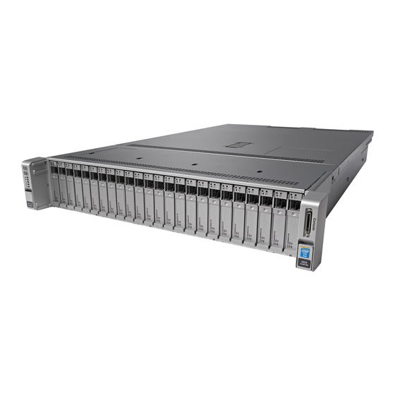
C H A P T E R Overview This chapter provides an overview of the Cisco UCS C240 server features. External Features Overview, page 1-1 Summary of Server Features, page 1-5 External Features Overview The figures in this chapter show an overview of external server features. - Page 16 16-drive backplane or a 24-drive backplane with an expander. When the 16-drive backplane is installed, only the first 16 drive bays are used. Figure 1-1 Cisco UCS C240 Server (Small Form-Factor Drives) Front Panel Features KVM connector Temperature status LED (used with KVM cable that provides two USB 2.0, one VGA, and one serial connector)
- Page 17 Large Form-Factor drives version of the server. This version of the server has a 12-drive backplane with an expander. Figure 1-2 Cisco UCS C240 Server (Large Form-Factor Drives) Front Panel Features HDD 1 HDD 2...
- Page 18 10 PCIe slots on riser 1: PCIe 1—full-height, half-length, x8 lane PCIe 2—full-height, half-length, x16 lane PCIe 3—full-height, half-length, x8 lane Serial port (RJ-45 connector) 11 Rear Identification button/LED USB port – Cisco UCS C240 Server Installation and Service Guide OL-25761-01...
-
Page 19: Summary Of Server Features
PCIe I/O Five horizontal PCIe expansion slots on two risers. Replacing a PCIe Card, page 3-40 for specifications of the slots. InfiniBand The bus slots in this server support the InfiniBand architecture. Cisco UCS C240 Server Installation and Service Guide OL-25761-01... - Page 20 • and expander). Holds up to twenty-four 2.5-inch hard drives or solid state drives. Cisco UCS C240 (small form-factor (SFF) drives, with 16-drive backplane, no • expander). Holds up to sixteen 2.5-inch hard drives or solid state drives. Cisco UCS C240 (large form-factor (LFF) drives, with 12-drive backplane and •...
-
Page 21: Installing The Server
Use the statement number provided at the end of each warning to locate its translation in the translated safety warnings that accompanied this device. Statement 1071 SAVE THESE INSTRUCTIONS Cisco UCS C240 Server Installation and Service Guide OL-25761-01... -
Page 22: Unpacking And Inspecting The Server
Model and serial number of the damaged unit • Description of damage • Effect of damage on the installation • Figure 2-1 Shipping Box Contents Server Documentation Power cord (optional, up to two) KVM cable Cisco UCS C240 Server Installation and Service Guide OL-25761-01... -
Page 23: Chapter 2 Installing The Server
Warning Statement 1074 All Cisco UCS C-Series rack servers are shipped with rail kits and are expected to be rack-mounted. To Caution ensure proper air flow it is necessary to rack the servers using the provided rail kits. Physically placing the units on top of one another or “stacking”... -
Page 24: Rack Requirements
• Equipment Requirements The slide rails supplied by Cisco Systems for this server do not require tools for installation if you install them in a rack that has square 0.38-inch (9.6 mm), round 0.28-inch (7.1 mm), or #12-24 UNC threaded holes. -
Page 25: Installing The Server In A Rack
The smaller #10-32 round mounting pegs are enclosed in the center of the compressible rear – pegs. However, to use the #10-32 pegs, you must use a bladed screwdriver to remove the square/round front pegs. Cisco UCS C240 Server Installation and Service Guide OL-25761-01... - Page 26 The inner rails are pre-attached to the sides of the server at the factory. You can order Note replacement inner rails if these are damaged or lost (Cisco PID UCSC-RAIL-2U-I). Align the inner rails that are attached to the server sides with the front ends of the empty slide rails.
- Page 27 Slide rail assembly on rack post Slide rail locking clip Right-front rack post Optional–If you want to install the cable management arm, continue with Installing the Cable Step 3 Management Arm (Optional), page 2-8. Cisco UCS C240 Server Installation and Service Guide OL-25761-01...
-
Page 28: Installing The Cable Management Arm (Optional)
Outer CMA tab attached to outer slide rail Rear of right slide rail assembly Inner CMA tab with spring-loaded peg “TOP” stamp on CMA arms facing upward attached to inner rail Cisco UCS C240 Server Installation and Service Guide OL-25761-01... -
Page 29: Reversing The Cable Management Arm (Optional)
Orientation for mounting to right slide rail “TOP” stamp on CMA arms Inner CMA tab attaches to CMA arm closest to server Captive thumbscrews on CMA arms Outer CMA tab attaches to CMA arm farthest from server Cisco UCS C240 Server Installation and Service Guide OL-25761-01... -
Page 30: Initial Server Setup
The NIC mode is Shared LOM EXT. • Shared LOM EXT mode enables the 1-Gb Ethernet ports and the ports on any installed Cisco virtual interface card (VIC) to access the Cisco Integrated Management Interface (Cisco IMC). If you want... - Page 31 Cisco card connection is not getting its IP address from a Cisco UCS Manager system because the server is in standalone mode, further DHCP requests from the Cisco card are disabled. Use the Cisco Card NIC mode if you want to connect to the CIMC through a Cisco card in standalone mode.
- Page 32 MAC addresses assigned to the Cisco IMC. The MAC address printed on the label is the beginning of the range of six contiguous MAC addresses. In Cisco IMC 2.0(1) and later, you can choose whether to use IPv4 or IPv6 IP addresses by Note checking either the IPv4 or IPv6 check box.
- Page 33 The default user name for the server is admin. The default password is password. Note To manage the server, see the Cisco UCS C-Series Rack-Mount Server Configuration Guide or the Cisco UCS C-Series Rack-Mount Server CLI Configuration Guide for instructions on using those interfaces.
-
Page 34: Nic Modes And Nic Redundancy Settings
LOM and Cisco Card interfaces are both enabled. In this mode, DHCP replies are returned to both the shared LOM ports and the Cisco card ports. If the system determines that the Cisco card connection is not getting its IP address from a Cisco UCS Manager system because the server is in standalone mode, further DHCP requests from the Cisco card are disabled. -
Page 35: System Bios And Cimc Firmware
See the Cisco Host Upgrade Utility Quick Reference Guide for your firmware level at the documentation roadmap link below. Your system firmware must be at minimum level 1.2 to use the Cisco Host Upgrade Utility. If Note your firmware is prior to level 1.2, you must use the methods below to update the BIOS and CIMC firmware individually. -
Page 36: Accessing The System Bios
Follow the instructions on the Exit menu screen to save your changes and exit the setup utility (or Press Step 6 F10). You can exit without saving changes by pressing Esc. Cisco UCS C240 Server Installation and Service Guide 2-16 OL-25761-01... -
Page 37: Service Headers And Jumpers
Figure 2-7 Service Header Locations 3 2 1 SAS1 Riser 1 FAN1 SAS2 FAN2 SAS2 CPU1 SAS1 FAN3 Riser 2 FAN4 FAN5 CPU2 FAN6 J2068 BIOS RCVR BOOT J2065 Clear CMOS Cisco UCS C240 Server Installation and Service Guide 2-17 OL-25761-01... -
Page 38: Using The Bios Recovery Header J2068
System would flash the BIOS image now... System would restart with recovered image after a few seconds... Step 6 Wait for server to complete the BIOS update, then remove the USB thumb drive from the server. Cisco UCS C240 Server Installation and Service Guide 2-18 OL-25761-01... - Page 39 During the BIOS update, the CIMC will shut down the server and the screen will be blank for Note about 10 minutes. Do not unplug the power cords during this update. The CIMC will power on the server after the update is complete. Cisco UCS C240 Server Installation and Service Guide 2-19 OL-25761-01...
-
Page 40: Procedure 2: Use Recovery Jumper And Recovery.cap File
Replace the top cover, replace the server in the rack, replace power cords and any other cables, then Step 14 power on the server by pressing the Power button. Cisco UCS C240 Server Installation and Service Guide 2-20 OL-25761-01... -
Page 41: Using The Clear Cmos Header J2065
Replace the top cover, replace the server in the rack, replace power cords and any other cables, then Step 11 power on the server by pressing the Power button. Cisco UCS C240 Server Installation and Service Guide 2-21 OL-25761-01... - Page 42 Chapter 2 Installing the Server Service Headers and Jumpers Cisco UCS C240 Server Installation and Service Guide 2-22 OL-25761-01...
-
Page 43: Chapter 3 Maintaining The Server
Server Monitoring and Management Tools Cisco Integrated Management Interface (CIMC) You can monitor the server inventory, health, and system event logs by using the built-in Cisco Integrated Management Controller (CIMC) GUI or CLI interfaces. See the user documentation for your firmware release at the following URL: http://www.cisco.com/en/US/products/ps10739/products_installation_and_configuration_guides_list.html... -
Page 44: Status Leds And Buttons
Off—The Ethernet link is idle. Network link activity • Green—One or more Ethernet LOM ports are link-active, but there is no activity. • Green, blinking—One or more Ethernet LOM ports are link-active, with activity. • Cisco UCS C240 Server Installation and Service Guide OL-25761-01... - Page 45 Amber—The server is in standby power mode. Power is supplied only to the CIMC • and some motherboard functions. Green—The server is in main power mode. Power is supplied to all server • components. Cisco UCS C240 Server Installation and Service Guide OL-25761-01z...
-
Page 46: Rear Panel Leds And Buttons
Green, solid—DC power OK, DC outputs OK. • 1-Gb Ethernet dedicated Off—link speed is 10 Mbps. • management link speed Amber—link speed is 100 Mbps. • Green—link speed is 1 Gbps. • Cisco UCS C240 Server Installation and Service Guide OL-25761-01... - Page 47 Off—No link is present. • Green—Link is active. • Green, blinking—Traffic is present on the active link. • Identification Off—The Identification LED is not in use. • Blue—The Identification LED is activated. • Cisco UCS C240 Server Installation and Service Guide OL-25761-01z...
-
Page 48: Internal Diagnostic Leds
DIMM fault LEDs (one next to each DIMM module) socket on the motherboard) Table 3-3 Internal Diagnostic LEDs, Definition of States LED Name State Internal diagnostic LEDs (all) Off—Component is functioning normally. • Amber—Component has failed. • Cisco UCS C240 Server Installation and Service Guide OL-25761-01... -
Page 49: Preparing For Server Component Installation
Emergency shutdown—Press and hold the Power button for 4 seconds to force the main power off • and immediately enter standby mode. Disconnect the power cords from the power supplies in your server to completely power off the server. Step 3 Cisco UCS C240 Server Installation and Service Guide OL-25761-01z... -
Page 50: Removing And Replacing The Server Top Cover
Tighten the captive thumbscrew that secures the rear edge of the cover to the chassis. Figure 3-4 Removing the Top Cover Front cover panel Rubber finger pads (two) Release button Captive thumbscrew Cisco UCS C240 Server Installation and Service Guide OL-25761-01... -
Page 51: Replaceable Component Locations
(two, on air baffle not shown in this view) 10 Software RAID 5 key header (SW RAID KEY) The Technical Specifications Sheet for this server, which includes component part numbers, is at: http://www.cisco.com/en/US/prod/collateral/ps10265/ps10493/C240M3_SFF_SpecSheet.pdf. Cisco UCS C240 Server Installation and Service Guide OL-25761-01z... -
Page 52: Serial Number Location
(An exception is the drive trays on the front panel, which are hot-swappable but not green). Some replaceable but non-hot-swappable components have light-blue plastic touch-points. • Cisco UCS C240 Server Installation and Service Guide 3-10 OL-25761-01... -
Page 53: Installing Or Replacing Server Components
Replacing a SCU Upgrade ROM Module, page 3-69 • Replacing a Software RAID Key Module, page 3-70 • Replacing Power Supplies, page 3-71 • Enabling or Disabling the Internal USB Port, page 3-74 • Cisco UCS C240 Server Installation and Service Guide 3-11 OL-25761-01z... -
Page 54: Replacing Hard Drives Or Solid State Drives
The server is orderable in three different versions, each with one of three different front panel/backplane configurations: Cisco UCS C240 (small form-factor (SFF) drives, with 24-drive backplane and expander). • Holds up to twenty-four 2.5-inch hard drives or solid state drives. -
Page 55: Drive Replacement Procedure
With the ejector lever on the drive tray open, insert the drive tray into the empty drive bay. Push the tray into the slot until it touches the backplane, then close the ejector lever to lock the drive in place. Cisco UCS C240 Server Installation and Service Guide 3-13 OL-25761-01z... - Page 56 Chapter 3 Maintaining the Server Installing or Replacing Server Components Figure 3-8 Replacing Hard Drives Release button Drive tray securing screws (4) Ejector lever – Cisco UCS C240 Server Installation and Service Guide 3-14 OL-25761-01...
-
Page 57: Replacing A Drive Backplane
Lift the backplane assembly, including steel tray and any expander card straight up from the chassis and Step 8 set it on an antistatic mat. If your SFF server has the 16-drive backplane, it does not use a SAS expander. Skip to Step Note Cisco UCS C240 Server Installation and Service Guide 3-15 OL-25761-01z... - Page 58 Rotate each blue-plastic lever down to the locked position. Stop when the levers click and lock. Replace the top cover. Step 18 Replace the server in the rack, replace cables, and then power on the server by pressing the Power Step 19 button. Cisco UCS C240 Server Installation and Service Guide 3-16 OL-25761-01...
- Page 59 Riser 2 FAN4 FAN5 CPU2 FAN6 1 Backplane assembly captive thumbscrews (two) 3 Location of motherboard connector BACKPLANE POWER 1 2 SAS expander cable connectors 4 Fan tray blue-plastic locking levers Cisco UCS C240 Server Installation and Service Guide 3-17 OL-25761-01z...
-
Page 60: Replacing A Sas Expander
Use a #2 Phillips-head screwdriver to install the two screws that secure the SAS expander to the backplane assembly steel tray (see Figure 3-10). Reconnect SAS cables to the new SAS expander. Step 6 Cisco UCS C240 Server Installation and Service Guide 3-18 OL-25761-01... - Page 61 FAN1 SAS2 FAN2 SAS2 CPU1 SAS1 FAN3 Riser 2 FAN4 FAN5 CPU2 FAN6 1 SAS expander securing screws (two) 3 Fan tray blue-plastic locking levers 2 SAS expander cable connectors Cisco UCS C240 Server Installation and Service Guide 3-19 OL-25761-01z...
-
Page 62: Replacing Fan Modules
(see Figure 3-12). Press down gently on the fan module until the finger-latches click and lock in place. Replace the top cover. Replace the server in the rack. Cisco UCS C240 Server Installation and Service Guide 3-20 OL-25761-01... - Page 63 SAS2 CPU1 SAS1 FAN3 Riser 2 FAN4 FAN5 CPU2 FAN6 Finger latches on each fan module Fan module fault LED on each fan module Connector on underside of fan module Cisco UCS C240 Server Installation and Service Guide 3-21 OL-25761-01z...
-
Page 64: Replacing The Motherboard Rtc Battery
Rotate each blue-plastic lever down to the locked position. Stop when the levers click and lock. Replace the top cover. Replace the server in the rack, replace cables, and power on the server by pressing the Power button. Cisco UCS C240 Server Installation and Service Guide 3-22 OL-25761-01... - Page 65 Replacing the Motherboard RTC Battery SAS1 Riser 1 FAN1 SAS2 FAN2 SAS2 CPU1 SAS1 FAN3 Riser 2 FAN4 FAN5 CPU2 FAN6 RTC battery holder on motherboard Fan tray blue-plastic locking levers (under fan tray) Cisco UCS C240 Server Installation and Service Guide 3-23 OL-25761-01z...
-
Page 66: Replacing Dimms
DIMMs and their sockets are fragile and must be handled with care to avoid damage during installation. Caution Cisco does not support 3rd-party DIMMs. Using non-Cisco DIMMs in the server might result in system Caution problems or damage to the motherboard. - Page 67 Fill black #2 slots in the channels second: A2, E2, B2, F2, C2, G2, D2, H2 – Fill black #3 slots in the channels third: A3, E3, B3, F3, C3, G3, D3, H3 – Cisco UCS C240 Server Installation and Service Guide 3-25 OL-25761-01z...
- Page 68 BIOS Setup utility that you can use to change the DDR memory mode to Power Saving mode, as described in the following procedure: Enter the BIOS setup utility by pressing the F2 key when prompted during bootup. Step 1 Cisco UCS C240 Server Installation and Service Guide 3-26 OL-25761-01...
-
Page 69: Dimm Replacement Procedure
Identifying a Faulty DIMM, page 3-27 • Replacing DIMMs, page 3-28 • Identifying a Faulty DIMM Each DIMM slot has a corresponding DIMM fault LED. See Figure 3-3 for the locations of these LEDs. Cisco UCS C240 Server Installation and Service Guide 3-27 OL-25761-01z... - Page 70 Push down evenly on the top corners of the DIMM until it is fully seated and the ejector levers on both ends lock into place. Replace the top cover. Replace the server in the rack, replace cables, and then power on the server by pressing the Power button. Cisco UCS C240 Server Installation and Service Guide 3-28 OL-25761-01...
-
Page 71: Replacing Cpus And Heatsinks
Table 3-6, you can install the CPU hardware by using the procedure in this section. If your server’s firmware and/or Cisco UCS Manager software is earlier than the required levels, use • the instructions in the Cisco UCS C-Series Servers Upgrade Guide for Intel E5-2600 v2 Series CPUs to upgrade your firmware. -
Page 72: Cpu Replacement Procedure
CPU. Do not attempt this procedure without the required tools, which are included with each CPU option kit. If you do not have the tool, you can order a spare: Cisco PID UCS-CPU-EP-PNP= for 10-, 8-, 6-, 4-, or 2-core CPUs (green); UCS-CPU-EP2-PNP= for v2 12-core CPUs (purple). - Page 73 Press the top button on the tool to grasp the installed CPU. Lift the tool and CPU straight up. Press the top button on the tool to release the old CPU on an anti-static surface. Cisco UCS C240 Server Installation and Service Guide 3-31 OL-25761-01z...
- Page 74 Make sure that the tabs on the tool are fully seated in the slots on the pedestal. Press the side lever on the tool to grasp and lock in the CPU. Lift the tool and CPU straight up off the pedestal. Cisco UCS C240 Server Installation and Service Guide 3-32 OL-25761-01...
- Page 75 Apply an alcohol-based cleaning solution to the old thermal pad and let it soak for a least 15 seconds. Wipe all of the old thermal pad off the old heatsink using a soft cloth that will not scratch the heatsink surface. Cisco UCS C240 Server Installation and Service Guide 3-33 OL-25761-01z...
- Page 76 Alternate tightening each screw evenly to avoid damaging the heatsink or CPU. Note Replace the top cover. Replace the server in the rack, replace cables, and then power on the server by pressing the Power button. Cisco UCS C240 Server Installation and Service Guide 3-34 OL-25761-01...
-
Page 77: Additional Cpu-Related Parts To Order With Rma Replacement Motherboards
Additional CPU-Related Parts To Order With RMA Replacement Motherboards When a return material authorization (RMA) of the motherboard or CPU is done on a Cisco UCS C-series server, there are additional parts that might not be included with the CPU or motherboard spare bill of materials (BOM). -
Page 78: Replacing A Mezzanine Card
Replace the server in the rack, replace cables, and then power on the server by pressing the Power button. If this was a replacement card, continue with Restoring RAID Configuration After Replacing a RAID Controller, page C-24. Cisco UCS C240 Server Installation and Service Guide 3-36 OL-25761-01... - Page 79 Maintaining the Server Installing or Replacing Server Components Figure 3-20 Replacing the Mezzanine Card (Shown With PCIe Riser 2 Removed) Mezzanine card connector on motherboard Mezzanine card securing screws (two) Cisco UCS C240 Server Installation and Service Guide 3-37 OL-25761-01z...
-
Page 80: Replacing A Pcie Riser
To remove a card, push down on the retaining clip on the hinged card retainer and then swing open the retainer to free the rear-panel tab of the card (see Replacing a PCIe Card, page 3-40). Cisco UCS C240 Server Installation and Service Guide 3-38 OL-25761-01... - Page 81 Replacing the PCIe Riser SAS1 Riser 1 FAN1 SAS2 FAN2 SAS2 CPU1 SAS1 FAN3 Riser 2 FAN4 FAN5 CPU2 FAN6 PCIe riser 1 alignment slot location PCIe riser 2 alignment slot locations (three) Cisco UCS C240 Server Installation and Service Guide 3-39 OL-25761-01z...
-
Page 82: Replacing A Pcie Card
Installing or Replacing Server Components Replacing a PCIe Card Cisco supports all PCIe cards qualified and sold by Cisco. PCIe cards not qualified or sold by Cisco are Caution the responsibility of the customer. Although Cisco will always stand behind and support the C-Series rack-mount servers, customers using standard, off-the-shelf, third-party cards must go to the third-party card vendor for support if any issue with that particular third-party card occurs. -
Page 83: Replacing A Pcie Card
For the list of supported PCIe adapters and other components, see the Technical Specifications Sheet at Note http://www.cisco.com/en/US/prod/collateral/ps10265/ps10493/C240M3_SFF_SpecSheet.pdf. If you are installing a Cisco UCS Virtual Interface Card, there are prerequisite considerations. See Note Special Considerations for Cisco UCS Virtual Interface Cards, page 3-43. - Page 84 PCIe Riser card Retainers (Slot 5 on PCIe Riser 2 Shown) Long card retainer Securing clip on hinged card retainer (on riser 2, slot 5 only) Card socket on riser Hinged card retainer Cisco UCS C240 Server Installation and Service Guide 3-42 OL-25761-01...
-
Page 85: Special Considerations For Cisco Ucs Virtual Interface Cards
3-44. 3. Slot 2 is the primary slot for Cisco UCS VIC cards and so should be reserved if a VIC card is required in your configuration. 4. A rear-panel tab adapter is required to fit the half-height cards in full-height slots 1, 2, 3, and 5. - Page 86 The user is responsible for any damage to equipment due to improper use of the override parameter. Cisco expressly disclaims any liability for damage arising from improper use of the override parameter.
-
Page 87: Raid Controller Card Cable Routing
RAID Controller Card Cable Routing If the PCIe card that you are installing or replacing is a RAID controller card, see RAID Controller Considerations, page C-1 for cable routing and other guidelines. Cisco UCS C240 Server Installation and Service Guide 3-45 OL-25761-01z... -
Page 88: Installing Multiple Pcie Cards And Resolving Limited Resources
ROMs for the onboard NICs to be booted from are enabled in the BIOS Setup Utility. Disable other option ROMs that are not needed to create sufficient memory space for the onboard NICs. Cisco UCS C240 Server Installation and Service Guide 3-46... - Page 89 Physically remove any unused PCIe cards. If the system has one or more Cisco virtual interface cards (VICs) installed, disable the PXE boot on the VICs that are not required for the system boot configuration by using the Network Adapters page in the CIMC WebUI to free up some 16-bit I/O resources.
-
Page 90: Installing An Nvidia Grid Or Tesla Gpu Card
This section includes the following topics: General NVIDIA GPU Card Configuration Rules, page 3-49 • NVIDIA GRID GPU Slot Population Rules, page 3-49 • NVIDIA Tesla GPU Slot Population Rules, page 3-49 • Cisco UCS C240 Server Installation and Service Guide 3-48 OL-25761-01... - Page 91 • time. This is because dual NVIDIA GPUs must be installed in slots 2 and 5 of the server, and a Cisco VIC must be installed in either slot 2 or slot 5. If you require two GPU cards and 10-Gb Ethernet connectivity, you must chooses a different supported adapter that can be used in a different slot.
-
Page 92: How To Determine Your Server Version
V02 and later versions of the server support GPU card installation without the GPU upgrade kit. Figure 3-25 Label and Version ID PID VID: ||||||||||||||||||||||||||||||||| UCSC-C240-M3S V01 PID/VID label on top of server Version ID on label Cisco UCS C240 Server Installation and Service Guide 3-50 OL-25761-01... -
Page 93: Installation Procedures
• Figure 3-26 Cisco UCS C240 GPU Kit Chassis mid-brace 8-to-8 pin GPU power cable adapter PCIe riser 2 Straight GPU power cable PCIe riser 1 Y GPU power cable Cisco UCS C240 Server Installation and Service Guide 3-51 OL-25761-01z... - Page 94 3-27). Install the new chassis mid-brace. Set the mid-brace in place while compressing the finger-latches on each end toward the center. Release the latches to lock the mid-brace into position. Cisco UCS C240 Server Installation and Service Guide 3-52 OL-25761-01...
- Page 95 Step 4 If you are installing only one GPU, use the straight GPU power cable. • If you are installing two GPU cards, use the “Y” GPU power cable. • Cisco UCS C240 Server Installation and Service Guide 3-53 OL-25761-01z...
- Page 96 Align the GPU card with the socket on the riser, then gently push the card’s edge connector into the socket. Press evenly on both corners of the card to avoid damaging the connector. Close the hinged card retainer, then the long-card retainer over the end of the card. Cisco UCS C240 Server Installation and Service Guide 3-54 OL-25761-01...
- Page 97 Install the new PCIe risers: Step 7 Install any other PCIe cards that you want to install into the new risers. If you are installing a Cisco UCS Virtual Interface Card (VIC), see the slot restrictions in Special Note Considerations for Cisco UCS Virtual Interface Cards, page 3-43.
- Page 98 The option ROM must be enabled in the BIOS Setup Utility for the slot in which you are Note installing the GPU card or it will not be recognized by the system. Cisco UCS C240 Server Installation and Service Guide 3-56 OL-25761-01...
- Page 99 Install the new PCIe risers: Step 5 Install any other PCIe cards that you want to install into the new risers. If you are installing a Cisco UCS Virtual Interface Card (VIC), see the slot restrictions in Special Note Considerations for Cisco UCS Virtual Interface Cards, page 3-43.
- Page 100 8-pin connector on the card. There are cable clips on the underside of the chassis mid-brace through which you can route the Note power cable. Cisco UCS C240 Server Installation and Service Guide 3-58 OL-25761-01...
- Page 101 Replace the server in the rack, replace cables, and then power on the server by pressing the Power Step 10 button. Continue with Installing Drivers to Support the NVIDIA GPU Cards, page 3-60. Step 11 Cisco UCS C240 Server Installation and Service Guide 3-59 OL-25761-01z...
-
Page 102: Installing Drivers To Support The Nvidia Gpu Cards
NVIDIA Tesla K20X 1.5(3) NVIDIA Tesla K40 1.5(7) Install the latest Cisco UCS C240 server BIOS by using the Host Upgrade Utility for the Cisco UCS C240 M3 server. Navigate to the following URL: http://www.cisco.com/cisco/software/navigator.html. Step 1 Click Servers–Unified Computing in the middle column. - Page 103 Restart the server. Step 4 Check that the virtual machine is able to recognize the NVIDIA card. In Windows, use the Device Step 5 Manager and look under Display Adapters. Cisco UCS C240 Server Installation and Service Guide 3-61 OL-25761-01z...
-
Page 104: Replacing An Internal Sd Card
Carefully push down on both ends of the PCIe riser to fully engage its circuit board connector with the socket on the motherboard. Replace the top cover. Replace the server in the rack, replace cables, and then power on the server by pressing the Power button. Cisco UCS C240 Server Installation and Service Guide 3-62 OL-25761-01... - Page 105 Figure 3-36 Internal SD Card Slot Locations on PCIe Riser 2 SAS1 Riser 1 FAN1 SAS2 FAN2 SAS2 CPU1 SAS1 FAN3 Riser 2 FAN4 FAN5 CPU2 FAN6 Slot SD2 Slot SD1 Cisco UCS C240 Server Installation and Service Guide 3-63 OL-25761-01z...
-
Page 106: Replacing The Lsi Raid Battery Backup Unit Or Supercap Power Module
Connect the cable from the RAID controller to the new backup unit. Replace the top cover. Replace the server in the rack, replace cables, and then power on the server by pressing the Power button. Cisco UCS C240 Server Installation and Service Guide 3-64 OL-25761-01... - Page 107 Chapter 3 Maintaining the Server Replacing an Internal SD Card Figure 3-37 Replacing a BBU or SCPM RAID Backup Unit RAID backup unit mounting points on removable air baffle Cisco UCS C240 Server Installation and Service Guide 3-65 OL-25761-01z...
-
Page 108: Installing A Trusted Platform Module
Log into the BIOS Setup utility with your BIOS Administrator password. On the BIOS Setup utility screen, select the Advanced tab. Select Trusted Computing to open the TPM Security Device Configuration screen. Change TPM SUPPORT to Enabled. Cisco UCS C240 Server Installation and Service Guide 3-66 OL-25761-01... -
Page 109: Enabling The Intel Trusted Execution Technology (Txt) Feature For The Tpm
Likewise, Intel TXT provides for a sealed portion of storage where sensitive data such as encryption keys can be kept, helping to shield them from being compromised during an attack by malicious code. To enable the TXT feature, follow these steps: Cisco UCS C240 Server Installation and Service Guide 3-67 OL-25761-01z... - Page 110 Watch during bootup for the F2 prompt, and then press F2 to enter BIOS setup. Select the Advanced tab. Select Intel TXT(LT-SX) Configuration and verify that TXT Support, VT-d Support, and VT Support are Enabled. Cisco UCS C240 Server Installation and Service Guide 3-68 OL-25761-01...
-
Page 111: Replacing A Scu Upgrade Rom Module
Printed circuit board on module Motherboard header Retention feature on module Retention feature in installed position For more information about using the module and embedded RAID, see Embedded MegaRAID Controller, page C-8. Cisco UCS C240 Server Installation and Service Guide 3-69 OL-25761-01z... -
Page 112: Replacing A Software Raid Key Module
Printed circuit board on module Motherboard header Retention feature on motherboard header Retention feature in installed position For more information about using the module and embedded RAID, see Embedded MegaRAID Controller, page C-8. Cisco UCS C240 Server Installation and Service Guide 3-70 OL-25761-01... -
Page 113: Replacing Power Supplies
For a DC power supply, push the electrical connector block into the power supply. For a DC power supply, see Note If you shut down the server, press the Power button to return the server to main power mode. Cisco UCS C240 Server Installation and Service Guide 3-71 OL-25761-01z... -
Page 114: Wiring A Dc Power Supply
Be sure uninsulated conductors are not accessible when cover is in place. Statement 1075 The recommended wire gauge is 8 AWG. The minimum wire gauge is 10 AWG. Note Cisco UCS C240 Server Installation and Service Guide 3-72 OL-25761-01... - Page 115 Step 8 with the power supply label, “+ DC”. Figure 3-42 930 W, –48 VDC Power Supply Connector Block Wire retainer lever Orange plastic button on top of the connector Cisco UCS C240 Server Installation and Service Guide 3-73 OL-25761-01z...
-
Page 116: Enabling Or Disabling The Internal Usb Port
Scroll to USB Port: Internal, press Enter, and then select either Enabled or Disabled from the pop-up Step 5 menu. Press F10 to save and exit the utility. Step 6 Cisco UCS C240 Server Installation and Service Guide 3-74 OL-25761-01... -
Page 117: Appendix
Table A-1 Physical Specifications Description Specification Height 3.4 in. (8.70 cm) Width (including slam-latches) 17.5 in. (44.55 cm) Depth 28.0 in. (71.23 cm) Weight (fully loaded) 60.0 lbs. (27.2 Kg) Cisco UCS C240 Server Installation and Service Guide OL-22326-01... -
Page 118: Power Specifications
1200 W AC Power Supply, page A-2 • 930W DC Power Supply, page A-3 • You can get more specific power information for your exact server configuration by using the Cisco UCS Power Calculator: http://www.cisco.com/assets/cdc_content_elements/flash/dataCenter/cisco_ucs_power_calculator/ 650 W AC Power Supply Table A-2 lists the specifications for each 650 W power supply (Cisco part number UCSC-PSU-650W). -
Page 119: Appendix A Server Specification
Appendix A Server Specifications Power Specifications 930W DC Power Supply Table A-4 lists the specifications for each 930 W DC power supply (Cisco part number UCSC-PSU-930WDC). Table A-4 930 W DC Power Supply Specifications Description Specification Class RSP1 Input DC input voltage range –48 to -60 VDC nominal... -
Page 120: Environmental Specifications
(when the server is stored) Sound power level Measure A-weighted per ISO7779 LwAd (Bels) Operation at 73°F (23°C) Sound pressure level Measure A-weighted per ISO7779 LpAm (dBA) Operation at 73°F (23°C) Cisco UCS C240 Server Installation and Service Guide OL-22326-01... -
Page 121: Appendix
Power Cord, 250 VAC 10 A M 2511 Plug Europe SFS-250V-10A-ID Figure B-5 Power Cord, 250 VAC 16A EL-208 Plug South Africa, United Arab Emirates, India SFS-250V-10A-IS Figure B-6 Power Cord, 250 VAC 10 A SI32 Plug Israel Cisco UCS C22 Server Installation and Service Guide OL-26646-01... -
Page 122: Supported Power Cords And Plugs
Cabinet Jumper Power Cord, 250 VAC 10 A, C13-C14 Connectors CAB-C13-C14-2M Figure B-14 Cabinet Jumper Power Cord, 250 VAC 10 A, C13-C14 Connectors CAB-C13-C14-AC Figure B-15 Cabinet Jumper Power Cord, 250 VAC 10 A, C13-C14 Connectors Cisco UCS C22 Server Installation and Service Guide OL-26646-01... -
Page 123: Ac Power Cord Illustrations
Cordset rating: 10 A, 250 V/500V Length: 2500mm Connector: Plug: EL 701C EL 206 (IEC 60320/C15) A.S. 3112-2000) Figure B-3 SFS-250V-10A-CN Cordset rating 10A, 250V Plug: (2500 mm) EL 218 (CCEE GB2009) Connector: EL 701 (IEC60320/C13) Cisco UCS C22 Server Installation and Service Guide OL-26646-01... - Page 124 Figure B-5 SFS-250V-10A-ID Cordset rating 16A, 250V Plug: (2500mm) EL 208 Connector: EL 701 Figure B-6 SFS-250V-10A-IS Cordset rating 10A, 250V/500V MAX (2500 mm) Connector: EL 701B Plug: (IEC60320/C13) EL 212 (SI-32) Cisco UCS C22 Server Installation and Service Guide OL-26646-01...
- Page 125 MP232-R Connector: IEC 60320 C15 Figure B-9 CAB-9K10A-UK Cordset rating: 10 A, 250 V/500 V MAX Length: 2500mm Connector: EL 701C Plug: EL 210 (EN 60320/C15) (BS 1363A) 13 AMP fuse Cisco UCS C22 Server Installation and Service Guide OL-26646-01...
- Page 126 Figure B-11 CAB-N5K6A-NA Cordset rating: 10 A, 250 V Length: 8.2 ft Plug: NEMA 6-15P Connector: IEC60320/C13 Figure B-12 CAB-9K12A-NA Cordset rating 13A, 125V (8.2 feet) (2.5m) Plug: Connector: IEC60320/C15 NEMA 5-15P Cisco UCS C22 Server Installation and Service Guide OL-26646-01...
- Page 127 CAB-C13-C14-2M, Jumper Power Cord (2 m) Cordset rating 10A, 250V (2.0 m) Connector: Plug: HS10S SS10A Figure B-15 CAB-C13-C14-AC, Jumper Power Cord (3 m) Cordset rating 10A, 250V (3.0 m) Connector: Plug: HS10S SS10A Cisco UCS C22 Server Installation and Service Guide OL-26646-01...
- Page 128 Appendix B Power Cord Specifications Supported Power Cords and Plugs Cisco UCS C22 Server Installation and Service Guide OL-26646-01...
-
Page 129: Appendix
RAID Controller Migration, page C-7 Embedded MegaRAID Controller, page C-8 • RAID Controller Cabling, page C-20 • Restoring RAID Configuration After Replacing a RAID Controller, page C-24 • For More Information, page C-25 • Cisco UCS C240 Server Installation and Service Guide OL-25761-01... -
Page 130: A P P E N D I X C Raid Controller Considerations
UCSC-RAID-11-C240 LFF/expander: 12 drives, LFF/expander: • • (Includes RAID 5 & 50) 12 internal (kit pair UCSC-CABLE4) SFF/no expander: 8 drives, SFF/no expander: • • 8 internal (kit of 4 UCSC-CABLE2) Cisco UCS C240 Server Installation and Service Guide OL-25761-01... - Page 131 3. Embedded RAID SAS drive control requires an optional SCU ROM upgrade chip to be installed on the motherboard. 4. Embedded RAID 5 support requires an optional software key. 5. See LSI Nytro MegaRAID 8110-4i Considerations, page C-4. Cisco UCS C240 Server Installation and Service Guide OL-25761-01...
-
Page 132: Lsi Nytro Megaraid 8110-4I Considerations
Use either all SAS or all SATA drives in a RAID group. Use the same capacity for each drive in the RAID group. • Never mix HDDs and SSDs in the same RAID group. • Cisco UCS C240 Server Installation and Service Guide OL-25761-01... -
Page 133: Battery Backup Units
(SCPMs). The units mount to clips on the removable air baffle (see Figure 3-37). The iBBU09 battery backup unit (BBU) has been phased out by Cisco and replaced with the SuperCap Note power module (SCPM). If you are replacing a BBU, order the SCPM for the replacement (UCS-RAID-CV-SC=). -
Page 134: Factory-Default Option Rom Settings
4. You cannot mix controller types in a server. A PCIe-style controller cannot be used when a mezzanine-style controller is used. 5. You cannot mix controller types in a server. A mezzanine-style controller cannot be used when a PCIe-style controller is used. Cisco UCS C240 Server Installation and Service Guide OL-25761-01... -
Page 135: Raid Controller Migration
Disable SCU storage support in BIOS. Install card. Install cables. HW RAID Not applicable Not allowed Onboard SCU Storage support is Disabled in BIOS Cisco UCS C240 Server Installation and Service Guide OL-25761-01... -
Page 136: Embedded Megaraid Controller
Notes on Supported Embedded MegaRAID Levels, page C-9 • Installing a SCU Upgrade ROM Module For Embedded RAID SAS Support, page C-10 • Installing a Software RAID Key Module for Embedded RAID 5 Support, page C-11 • Cisco UCS C240 Server Installation and Service Guide OL-25761-01... -
Page 137: Notes On Supported Embedded Megaraid Levels
For example, you cannot configure a three-drive array into RAID 0 and RAID 5 VDs. Unlike RAID 0, 1, and 5, you cannot create multiple RAID 10 VDs from the same array. A single RAID 10 VD uses up the entire array. Cisco UCS C240 Server Installation and Service Guide OL-25761-01... -
Page 138: Installing A Scu Upgrade Rom Module For Embedded Raid Sas Support
Note The Cisco PID UCSC-RAID-ROM5= includes the SCU upgrade ROM module. The Cisco PID UCSC-RAID-ROM55= includes the SCU upgrade ROM module and the RAID 5 key. To install a SCU upgrade ROM module, follow these steps: Locate the header labelled “PCH UPGRD SKU ROM” under any cables that are routed along the chassis... -
Page 139: Enabling The Embedded Raid Controller In The Bios
Select the Advanced tab, then South Bridge. Step 2 Step 3 Set Onboard SCU Storage Support to Enabled. Step 4 Press F10 to save your changes and exit the utility. Cisco UCS C240 Server Installation and Service Guide C-11 OL-25761-01... -
Page 140: Disabling The Embedded Raid Controller In The Bios
This section contains the following topics: Downloading the LSI MegaSR Drivers, page C-13 • • Microsoft Windows Driver Installation, page C-13 • Linux Driver Installation, page C-15 Cisco UCS C240 Server Installation and Service Guide C-12 OL-25761-01... -
Page 141: Microsoft Windows Driver Installation
See the following URL: http://www.cisco.com/cisco/software/navigator.html Click Unified Computing and Servers in the middle column. Click Cisco UCS C-Series Rack-Mount Standalone Server Software in the right-hand column. Click your model of server in the right-hand column. Click Unified Computing System (UCS) Drivers. - Page 142 Properties. On the Driver tab, click Update Driver to open the Update Device Driver wizard, and then follow the Step 4 wizard instructions to update the driver. Cisco UCS C240 Server Installation and Service Guide C-14 OL-25761-01...
-
Page 143: Linux Driver Installation
MegaRAID stack. Note The LSI MegaSR drivers that Cisco provides for Red Hat Linux and SUSE Linux are for the original GA versions of those distributions. The drivers do not support updates to those OS kernels. Preparing Physical Installation Diskettes For Linux This section describes how to prepare physical Linux installation diskettes from the driver image files, using either the Windows operating system or the Linux operating system. - Page 144 Under Red Hat Linux and SuSE Linux, you can use a driver diskette utility to create disk images from image files. Perform the following steps to create the driver update disk: Download the Cisco UCS C-Series drivers ISO, as described in Downloading the LSI MegaSR Drivers,...
- Page 145 Diskettes For Linux, page C-15. Then return to Step 4 of this procedure. To install from a virtual floppy disk: Download and save the Cisco UCS C-Series drivers ISO, as • described in Downloading the LSI MegaSR Drivers, page C-13.
- Page 146 Then return to Step 4 of this procedure. • To install from a virtual floppy disk: Download and save the Cisco UCS C-Series drivers ISO, as described in Downloading the LSI MegaSR Drivers, page C-13. Then continue with the next step.
- Page 147 The following message appears: LSI Soft RAID Driver Updates added. Step 15 At the menu, select the driver update medium and press the Back button. Step 16 Continue and complete the installation process by following the prompts. Cisco UCS C240 Server Installation and Service Guide C-19 OL-25761-01...
-
Page 148: Raid Controller Cabling
RAID Controller Cabling RAID Controller Cabling This section includes the following topics: Cable Routing, page C-20 • Cisco UCS C240 Server Cabling Instructions, page C-21 • Cable Routing The RAID controller connectors in this server are shown in Figure C-2. The red line indicates the recommended cable routing path from the backplane to the possible controller locations. -
Page 149: Cisco Ucs C240 Server Cabling Instructions
The server is orderable in three different versions, each with one of three different front panel/backplane configurations: Cisco UCS C240 (small form-factor (SFF) drives, with 24-drive backplane and expander). • Holds up to twenty-four 2.5-inch hard drives or solid state drives. -
Page 150: Sff 16-Drive Backplane, No Expander
Connect cable 1 from the second card SAS1 connector to the SAS3 connector on the backplane. Connect cable 2 from the second card SAS2 connector to the SAS4 connector on the backplane. Cisco UCS C240 Server Installation and Service Guide C-22... -
Page 151: Lff 12-Drive Backplane With Expander
Connect cable 1 from connector SAS1 on the card to the SAS1 connector on the expander. Connect cable 2 from connector SAS2 on the card to the SAS2 connector on the expander. Cisco UCS C240 Server Installation and Service Guide C-23... -
Page 152: Restoring Raid Configuration After Replacing A Raid Controller
F quickly enough when prompted. In this case, reboot the server and try the import operation again wen you are prompted to press F. 0 Virtual Drive(s) found on host adapter. Cisco UCS C240 Server Installation and Service Guide C-24 OL-25761-01... -
Page 153: For More Information
Full LSI documentation is also available: LSI MegaRAID SAS Software User’s Guide (for LSI MegaRAID) • http://www.cisco.com/en/US/docs/unified_computing/ucs/3rd-party/lsi/mrsas/userguide/LSI_MR_SAS_SW_UG.pdf LSI SAS2 Integrated RAID Solution User Guide (for LSI SAS 2008) • http://www.cisco.com/en/US/docs/unified_computing/ucs/3rd-party/lsi/irsas/userguide/LSI_IR_SAS_UG.pdf Cisco UCS C240 Server Installation and Service Guide C-25 OL-25761-01... - Page 154 Appendix C RAID Controller Considerations For More Information Cisco UCS C240 Server Installation and Service Guide C-26 OL-25761-01...
-
Page 155: Appendix
The Cisco UCS integration instructions have been moved to the integration guides found here: Cisco UCS C-Series Server Integration with UCS Manager Guides Refer to the guide that is for the version of Cisco UCS Manager that you are using. Cisco UCS C240 Server Installation and Service Guide... -
Page 156: A P P E N D I X D Installation For Cisco Ucs Integration
Appendix D Installation for Cisco UCS Integration Cisco UCS C240 Server Installation and Service Guide OL-25761-01...