
Related Manuals for Husqvarna P 525D


Summary of Contents for Husqvarna P 525D
- Page 1 Oper ator ′ s manual P 520D P 525D Please r ead the operator’s manual carefully and make sure you E E E E n n n n g g g g l l l l i i i i s s s s h h h h...
-
Page 2: Table Of Contents
CONTENTS Contents Cleaning the air filter ............ Replacing the air filter ..........CONTENTS Cleaning the engine and muffler ........Contents ..............Check the safety system ..........Ser vice journal Replacing the light bulbs ..........Pre-deliv ery service ............. Main fuse ..............After the first 25 hours .......... -
Page 3: Ser Vice Journal
Ser vice journal Pre-deliver y service 14 Tell customer about: The requirement and advantages of servicing the 1 Charge the battery for at least 4 hours at max. 3 machine according to the service plan amp. Servicing and the influence of this journal on the 2 Check coolant level and antifreeze. -
Page 4: Intr Oduction
Dear Customer , Thank y ou for choosing a Husqvarna Rider. Husqvarna Riders are built to a unique design with a front-mounted cutting unit and a patented articulated steering. Riders are designed for maximum efficiency even in small or confined areas. The closely grouped controls and pedal-operated hydrostatic transmission also contribute to the performance of this machine. -
Page 5: Good Service
INTR ODUCTION Good ser vice Husqv arna products are sold all over the world and ensures that you, the customer, get the best support and service. For example, before this machine was delivered it was inspected and adjusted by your dealer. See the certificate in the Service Journal in this manual. -
Page 6: Key To Symbols
KEY T O SYMBOLS Symbols Warning: rotating parts. Keep hands and feet clear. These symbols are on the machine and in the instr uctions. WARNING! Careless or incorrect use can result in serious or fatal injury to the Watch your hands and other body parts operator or others. -
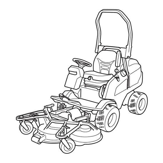
Page 7: Wha T Is What
WHA T IS WHA T? 18 19 24 25 20 21 22 23 14 15 16 17 Location of the contr ols 1 Knob for seatback angle 14 Counter 2 Throttle trigger 15 Temperature gauge 3 Power outlet 16 Knob for adjustment of the seat suspension 4 Switch for the power outlet 17 Lever for longitudinal seat adjustment 5 Control for cutting unit drive... -
Page 8: Safety Instr Uctions
SAFETY INSTR UCTIONS Saf ety instructions • Remember that the driver is responsible for dangers or accidents. These instr uctions are for your safety. Read them carefully. • Never carry passengers. The machine is only intended to be used by one person. Insure y our Rider •... -
Page 9: Driving On Slopes
SAFETY INSTR UCTIONS This is what y ou do • Never allow children or other persons not trained in the use of the machine to use or service it. Local laws may • Remove obstacles such as stones, branches, etc. regulate the age of the user. -
Page 10: Children
SAFETY INSTRUCTIONS Children • Electrical shocks can cause injuries. Do not touch cables when the engine is running. Do not test the ignition system with your fingers. • Serious accidents may occur if you fail to be on your guard for children in the vicinity of the machine. -
Page 11: Transport
SAFETY INSTRUCTIONS • Stop and inspect the equipment if you run over or into anything. If necessary, make repairs before starting. • Never make adjustments with the engine running. • The machine is tested and approved only with the equipment originally provided or recommended by the manufacturer. -
Page 12: Presentation
Throttle trigger Cutting unit The throttle control regulates the engine speed, and thereby P 520D and P 525D can be equipped with two different cutting also the rotation speed of the blades. units. To increase or reduce the engine speed the control is moved forwards or backwards. -
Page 13: Lever For Hydraulic Lift Of Attachments
PRESENTATION Adjusting the cutting height Pull the lever backwards to engage the transport position. The unit is then raised. The cutting height can be adjusted to seven different positions. Select the required cutting height (1-7) using the cutting height adjusters. Set the knobs horizontally so that they do not snag on bushes and the like. -
Page 14: Seat
PRESENTATION Seat • The lumbar support is adjusted with the knob on the left side of seat back . The seat has a jointed attachment on the front edge and can be tipped forward. To fold the seat forward, the latch for the seat must be operated. -
Page 15: Instrument Panel
PRESENTATION The power outlet is switched on and off using power switch on 2 Oil pressure, check oil level and top up if necessary. the control panel. 3 Ignition 4 Battery charging 5 Power transmission connected 6 Parking brake 7 Spotlight 8 Switch for the lights Bypass valves The power outlet works even if the ignition is turned off. -
Page 16: Rops (Roll Over Protective Structure)
PRESENTATION ROPS (Roll Over Protective Auxiliary lift system Structure) The auxiliary lift system transfers the weight of the cutting unit pivot wheel to the machine's front wheel. ROPS is a protective frame that reduces the risk of injury in the event of overturning. Use ROPS and a safety belt when The effect of the auxiliary lift system can be adjusted by driving on slopes. -
Page 17: Starting Engine
STARTING ENGINE Before starting 5 Turn the ignition key to the ignition position and hold it there until the indicator light on the instrument panel goes out. • Read the safety instructions and information concerning the placement of controls and functions before starting. •... -
Page 18: Starting The Engine With A Weak Battery
STARTING ENGINE Starting the engine with a weak battery WARNING! Lead-acid batteries produce explosive gases. Avoid sparks, open flames and smoking close to batteries. Always wear protective glasses in the vicinity of batteries. If the battery is too weak to start the engine, it should be recharged. -
Page 19: Driving
DRIVING Driving the Rider Turn off the cutting unit using the PTO button. 1 Release the parking brake before driving 1 Apply the parking brake by moving the handle downward. 2 Carefully press down one of the pedals until the required speed is obtained. -
Page 20: Cutting Tips
DRIVING Cutting tips WARNING! Clear the lawn from stones and other objects which can be thrown out by the blades. • Localise and mark stones and other fixed objects to avoid collision. • Start with a high cutting height and reduce down until the required mowing results are obtained. -
Page 21: Maintenance
Maintenance Maintenance schedule The following is a list of the maintenance which should be conducted on the machine. For those points not described in this manual, visit an authorised service workshop. Maintenance Daily maintenance Maintenance interval in hours Before After work is 40 100 200 400 800 starting completed... -
Page 22: Cleaning
Maintenance Cleaning Side cover Loosen the screws holding the side cover and remove it. Clean the machine directly after use. It is much easier to wash off grass cuttings before they dry. Oily dirt can be removed using a cold degreasing agent. Service hatch Spray on a thin layer. -
Page 23: Adjustment Of Pump And Alternator Belt
WARNING! A poorly adjusted parking brake can result in reduced braking ability. Replacement of fuel filter P 520D and P 525D have two fuel filters. A pre-filter and main filter. • Take off the old belt and fit the new one. -
Page 24: Cleaning The Air Filter
Maintenance Replacing the air filter The main filter has a paper insert that is changed as follows. WARNING! The exhaust system is hot. Let it cool before starting to replace the air filter. If the engine seems to lack power or does not run smoothly this may be because the air filter is clogged. -
Page 25: Check The Safety System
Maintenance Check the safety system 5 Lift out the bulbs from the insert. 6 Insert the new bulbs. Make sure you use your thumb to The machine is equipped with a safety system that prevents support the front. starting or driving under the following conditions. The engine must only be possible to start when the following conditions are met: •... -
Page 26: Check The Battery
Maintenance Check the battery Fitting the cutting head 1 Place the machine on a flat surface and apply the parking WARNING! Lead-acid batteries produce brake. explosive gases. Avoid sparks, open flames 2 Start the engine and lower the lift arms to floating mode. and smoking close to batteries. -
Page 27: Removing The Cutting Unit
Maintenance 9 Remove the service hatch. 3 Turn off the motor. 4 Remove the lifting eyes from the cutting unit. 10 Fit the rear universal drive shaft. 5 Start the engine and lower the cutting unit to the lowest position (floating mode). The cutting unit now hangs free at the back. -
Page 28: Service Position For The Cutting Unit
Maintenance Service position for the cutting unit If it is the first time the service strut is removed, remove the safety strap from the strut and place it in the storage compartment under the seat. The cutting head can be placed in the service position to provide easy access for cleaning, repairs and servicing. -
Page 29: Cutting Height And Tilt Angle Adjustment
Maintenance Cutting height and tilt angle 12 Secure the cutting unit with the safety belt, which is stored in the storage compartment under the seat. adjustment. When a cutting unit is installed the cutting height and tilt angle need to be adjusted The adjustment must be made in the stated order. -
Page 30: Replacing The Cutting Unit Belts
Maintenance Tilt angle 5 Check that the belt tensioning equipment is not jammed or binding and replace the spring. • Place the machine on a flat surface. 6 Insert the new belt in place and replace the bevel gear. • Check the tyre pressures. -
Page 31: Adjustment Of Pto Belts
Maintenance Adjustment of PTO belts 8 Pull the new belts through the gap between the spacer ring and the hydraulic pump. 1 Tighten screw (4) until the sleeve bottoms against the frame bracket. Tighten lock nut (3) whilst holding screw (4) firmly. -
Page 32: Change Coolant
ASTM D 3306-89 or AS 2108-1977 (indicated on the packaging). The antifreeze must be intended for alloy engines. Your Husqvarna supplier can provide the right type of antifreeze. Use antifreeze all year round and even in climates where there is no risk of frost. -
Page 33: Lubrication
Lubrication Lubrication schedule Legend for the lubrication schedule General Remove the ignition key to prevent unintentional movements during lubrication. Filter replacement When lubricating with an oilcan, it ought to be filled with engine oil. Oil change When lubricating with grease, unless otherwise stated, grease 503 98 96-01 or another chassis or ball bearing grease offering good corrosion protection shall be used. -
Page 34: Accessories
Lubrication Accessories • The universal drive shaft has two grease nipples, one on the front hub and one on the rear hub. Lubricate with a grease gun until the grease is forced out. Lubrication or other maintenance of optional equipment or accessories is not described in this manual. -
Page 35: The Drive Shaft Front Support Bearing
Lubrication The drive shaft front support Link brace bearing • 2 grease nipples, one on each side. Lubricate with a grease gun until the grease is forced out. Lubricate with a grease gun until the grease is forced out. Checking the engine’s oil level. The drive shaft rear support bearing Check the oil level in the engine when the Rider stands 2 grease nipples. -
Page 36: Changing The Oil Filter
Lubrication Changing the oil filter The following oil classes are recommended: • API Service Class: CH4 or ACEA E5 or higher. WARNING! Engine oil can be very hot if it is drained directly after stopping the engine. Choose an oil with viscosity according to the temperature Allow the engine to cool somewhat first. -
Page 37: Check The Oil Level In The Transmission Gearboxes
Lubrication Check the oil level in the Lubricating the cables transmission gearboxes Remove the cable´s rubber casing when lubricating. • Use the oil dipstick to check that there is oil in the Grease both ends of the cables and move the controls to end transmission. -
Page 38: Troubleshooting Schedule
Troubleshooting schedule Problem Procedure Engine does not start There is no fuel in the fuel tank Air in fuel system Incorrect fuel type Ignition system inoperative Serious engine damage Starter motor does not turn over the engine Battery flat Poor contact affecting the battery terminal cable connections, ignition lock, or starter Power take off (PTO) activated Air in fuel system... - Page 39 Troubleshooting schedule Engine overheats Engine overloaded Coolant level too low Air intake or cooling flanges blocked Fan damaged Too little or no oil in engine Incorrect radiator cap Coolant pump drive belt broken Battery does not charge One or more battery cells faulty Poor contact on the battery terminal cable connectors Defective alternator Alternator belt broken or slipping...
-
Page 40: Electrical System
ELECTRICAL SYSTEM Numbers correspond to: 6 Inductive sensor, parking brake 1 Switch for the lights 7 Switch for the power outlet 2 Instrument panel 8 Power outlet 3 Lights 9 Electrical connection box 4 Counter 10 Seat switch 5 Ignition lock 11 Main fuse, 125 A 40 –... -
Page 41: Wir Ing Diagram
ELECTRICAL SYSTEM Wiring diagram P 520D – 41 English... -
Page 42: Electrical System
ELECTRICAL SYSTEM 42 – English... -
Page 43: Electrical System
ELECTRICAL SYSTEM – 43 English... -
Page 44: Electrical System
ELECTRICAL SYSTEM 44 – English... -
Page 45: Electrical System
ELECTRICAL SYSTEM – 45 English... -
Page 46: Electrical System
ELECTRICAL SYSTEM 46 – English... -
Page 47: Wir Ing Diagram
ELECTRICAL SYSTEM Wiring diagram P525 D – 47 English... - Page 48 ELECTRICAL SYSTEM 48 – English...
- Page 49 ELECTRICAL SYSTEM – 49 English...
- Page 50 ELECTRICAL SYSTEM 50 – English...
- Page 51 ELECTRICAL SYSTEM – 51 English...
- Page 52 ELECTRICAL SYSTEM 52 – English...
-
Page 53: Storage
Storage Winter storage Service At the end of the season, or if the machine is going to stand Low season is the most suitable time to perform a service or idle for more than 30 days, it should immediately be made overhaul of the machine in order to ensure high function ready for storage. -
Page 54: Technical Data
TECHNICAL DATA P 520D P 525D Dimensions Length without cutting unit, cm/in 208 / 81,9 211 / 83.07 Width without cutting unit, cm/in 111 / 44.1 114 / 44.88 Height, cm/ft 129 / 50,8 133 / 52.4 Unladen weight excluding cutting unit, kg/lb... -
Page 55: Ec-Declar Ation Of Conformity
EC-declaration of conformity (Applies to Europe only) Husqvarna AB, SE-561 82 Huskvarna, Sweden, tel.: +46-36-146500, hereby declares that Husqvarna P 520D and P 525D from 2012’s serial numbers and onwards (the year is clearly stated in plain text on the rating plate with subsequent serial number), complies with the requirements of the COUNCIL’S DIRECTIVE:... - Page 56 Original instructions 1154837-26 ´®z+Vsh¶6}¨ ´®z+Vsh¶6}¨ 2012-04-12...