Honeywell HD4U User Manual
Day/night ultra wide dynamic fixed dome camera ntsc/pal
Hide thumbs
Also See for HD4U:
- Brochure (2 pages) ,
- Brochure & specs (2 pages) ,
- Quick install manual (2 pages)

Related Manuals for Honeywell HD4U


Summary of Contents for Honeywell HD4U
-
Page 1: User Guide
Day/Night Ultra Wide Dynamic Fixed Dome Camera NTSC / PAL HD4U HD4UX User Guide Document 800-00031 – Rev A – 04/08... - Page 2 Revisions Issue Date 04/08 Revisions New document.
-
Page 3: Explanation Of Graphical Symbols
Warnings Installation and servicing should be performed only by qualified and experienced technicians to conform to all local codes and to maintain your warranty. WARNING! 12 VDC/24 VAC models require the use of CSA Certified/UL Listed Class 2 power adapters to ensure compliance with electrical safety standards. -
Page 4: Fcc Compliance Statement
FCC Compliance Statement Information to the User: This equipment has been tested and found to comply with the limits for a Class B digital device. Pursuant to Part 15 of the FCC Rules, these limits are designed to provide reasonable protection against harmful interference in a residential installation. This equipment generates, uses, and can radiate radio frequency energy and, if not installed and used in accordance with the instruction manual, may cause harmful interference to radio communications. -
Page 5: Table Of Contents
HD4U Mounting Template ........ -
Page 6: Introduction
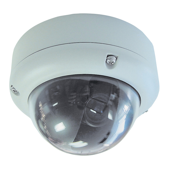
Introduction The unobtrusive, low-profile design of the HD4U/X CCTV Camera is ideal for indoor and outdoor installations in commercial and residential venues. Before You Begin Please read this guide carefully before you install the HD4U/X CCTV Camera. Keep this guide for future reference. -
Page 7: Equipment Required
Equipment Required You will require the following tools to complete the installation: • Phillips screwdriver • Tools supplied in the hardware kit (three Allen keys: one each for the security screw on the lid, the conduit plug locking screw, and the lens locking screw) •... -
Page 8: Installation
The wiring can be completely concealed to reduce the risk of tampering. Mounting the Camera The HD4U/X Camera is designed to be surface mounted on a wall or ceiling. Before you mount the camera, use the mounting template provided to mark and pre-drill the holes. HD4U/X dome... -
Page 9: Connecting Cables Through The Housing Base
Connecting Cables Through the Housing Base For installations that require pulling cables through the grommet located in the bottom of the base: Use a sharp knife to cut an ! opening in the base gasket (see opening should be only big enough to feed the cable assembly through. Pull the cabling through the opening. -
Page 10: Connecting Cables Through The Side Conduit
Connecting Cables Through the Side Conduit Peel back the bottom flat gasket below the side conduit just enough to expose the security screw. Use the supplied Allen key to loosen and remove the security screw (see Use a flat screwdriver to unscrew the conduit plug. Pull the cables through the hole. -
Page 11: Electrical Box Installations
Electrical Box Installations Figure 3 illustrates how to mount the HD4U/X directly to a 4S electrical box or directly to wall or ceiling. For 4S electrical box installations, you can use the supplied adapter plate to cover ceiling or wall imperfections around the electrical box opening. - Page 12 Figure 4 illustrates how to mount the HD4U/X directly to a double gang or single gang electrical box. Figure 4 Double Gang/Single Gang Electrical Box Installation (Single Gang Shown) Ceiling/wall Secure the HD4U/X base with screws appropriate to your installation (not...
-
Page 13: Connecting The Wiring
Video: female BNC Red+ Adjusting the Camera To adjust the HD4U/X Camera: Apply 12 VDC or 24 VAC power to the camera and monitor the video signal. Loosen the screws that lock the gimbal assembly in place (see Adjust the camera carrier to the desired view. -
Page 14: Adjusting The Lens Focus
Figure 6 Gimbal Adjustment Top view Locking screw. Loosen to adjust Horizontal (B). Set focal length (bottom) Adjusting the Lens Focus Lenses are pre-focused at the factory but may require a final adjustment after installation because the optical effect of the dome may cause a slight defocusing of the lens. TECH TIP! To check the focus, hold the dome over the lens while making any adjustments. -
Page 15: Camera Setup
Camera Setup Camera Functions CAMERA SETUP .. VIEWING .. Select a menu, WDR PRESETS .. then press down DAY/NIGHT SETUP .. VERSION INFO .. the joystick to > RESTORE DEFAULTS <NO> enter the EXIT submenu. OSD Menu Structure 4 Setup menus for easy programming CAMERA VIEWING... -
Page 16: Configuring The Wdr Presets
Configuring the WDR Presets Select the appropriate camera mode for the lighting conditions. MENU MENU CAMERA SETUP .. VIEWING .. > WDR PRESETS .. INDOOR> DAY/NIGHT SETUP .. VERSION .. RESTORE DEFAULTS EXIT SAVE & EXIT The table below explains the Preset options on the WDR PRESETS menu. Double-click a Preset to display a read-only screen showing the factory settings. -
Page 17: Optimizing The Camera Setup
<AES> The AES (Automatic Electronic Shutter) feature compensates for excessive light levels by automatically adjusting the shutter speed of the camera. Select from: HIGHLIGHTS for optimum exposure of bright areas of the scene. SHADOWS for optimum exposure of dark areas of the scene. Optimizing the Camera Setup Note This menu is for advanced users only. - Page 18 >SYNC Synchronize the vertical interval sync pulse of your camera with other equipment to reduce the effect of picture roll on the monitor. Select either: LINE LOCK <INTERNAL> (default) for cameras using DC power or when line lock is not required, >...
-
Page 19: Setting The Camera Image Properties
<ATW Xtnd> Automatic Tracking White Balance (Extended Range). Continuously monitors the color temperature while an internal micro controller sets the white balance. Select this mode when the scene illumination varies between indoor scenes and outdoor scene lighting. Operating color temperature range is 2000K to 11000K. >ADVANCED Opens the ADVANCED WHITE BALANCE menu where you can adjust the magenta or WHITE BAL .. - Page 20 >FLIP Select either: <ON> to reverse the image horizontally on the video monitor, or <OFF> (default) > ID DISPLAY. Select ON to open the CAMERA ID SETUP screen where you can add a CAMERA ID (title) of up to 8 characters. CAMERA ID SETUP Move the cursor (>) to CAMERA ID, then press down on the joystick.
-
Page 21: Setting The Day/Night Control
Setting the Day/Night Control The table below explains the options on the DAY/NIGHT SETUP menu. DAY/NIGHT SETUP DAY/NIGHT SETUP AUTO NIGHT MODE .. > TDN DELAY PREVIOUS PAGE . Note This setting is dependent on the AGC setting (See >DAY/NIGHT SETUP Select either: <AUTO>... -
Page 22: Restoring Settings
Restoring Settings On the main MENU, select RESTORE DEFAULTS, then YES followed by ENTER (middle button). This reloads the factory default camera settings. Caution This action replaces all custom settings. MENU CAMERA SETUP … VIEWING … WDR PRESETS <Custom> DAY/NIGHT SETUP … VERSION …... -
Page 23: Installing The Enclosure Cover
Installing the Enclosure Cover To install the enclosure cover, use the Allen key (supplied) to secure the HD4U/X dome enclosure to the base with four #8-32 security screws. Figure 7 Enclosure Cover Installation #8-32 security screws (x3) Routine Maintenance Use regular liquid cleaners to remove dirt and grime from the HD4U/X dome. -
Page 24: Solving Common Technical Issues
AGC had changed, thus customizing your setup. Custom affects WDR allows you to modify the dynamic range and exposure of the preset. preset Call Honeywell Technical Support for additional assistance (see Specifications for details. Warranty and... -
Page 25: Warranty And Service
Warranty and Service Subject to the terms and conditions listed on the Product warranty, during the warranty period Honeywell will repair or replace, at its sole option, free of charge, any defective products returned prepaid. In the event you have a problem with any Honeywell product, please call Customer Service at 1.800.796.CCTV for assistance or to request a Return Merchandise Authorization... -
Page 26: Specifications
Specifications Video Signal Specifications Video Standard: Scanning System: Image Sensor: Number of Pixels (H x V): Dynamic Range: Day/Night Operation: Minimum Illumination: Horizontal Resolution: Lens Type: Video Output: Sync System: Signal to Noise Ratio: Auto Gain Control (AGC): Automatic Electronic Shutter (AES): Lens Iris Control: White Balance: Line Lock Phase Adjust:... -
Page 27: Dimensions
Temperature: Mechanical Specifications Dimensions (D) x (H): Weight: Housing Construction: Housing Finish: Video Output: Power Input: Regulatory Emissions: Immunity: Safety: Environmental: Dimensions Document 800-00031 Rev A 04/08 Operating: -13°F to +122°F (-25°C to +50°C) Storage: -4°F to +140°F (-20°C to +60°C) 5.5 in. -
Page 28: Cable Guidelines
Calculations are based on an unregulated linear power supply, which would be the worst case. Using a regulated or switching power supply can increase the cable distance. Honeywell recommends using a CSA Certified/UL listed Class 2 power adapter to ensure compliance with electrical safety standards. -
Page 29: Hd4U Mounting Template
HD4U Mounting Template Document 800-00031 Rev A 04/08... - Page 31 Document 800-00031 Rev A 04/08...
- Page 32 ℡ +34.902.667.800 © 2008 Honeywell International Inc. All rights reserved. No part of this publication may be reproduced by any means without written permission from Honeywell Video Systems. The information in this publication is believed to be accurate in all respects. However, Honeywell Video Systems cannot assume responsibility for any consequences resulting from the use thereof.