
Related Manuals for Honeywell HD31H(X)


Summary of Contents for Honeywell HD31H(X)
- Page 1 HD31H(X) HD30H(X) HD40H(X) Performance Series Camera User Guide Document 800-18605 – Rev A – 06/2014...
-
Page 2: Regulatory Information
This manual applies to HD40H(X), HD30H(X) and HD31H(X) cameras. The information in this publication is believed to be accurate in all respects. However, Honeywell cannot assume responsibility for any consequences resulting from the use thereof. The information contained herein is subject to change without notice. -
Page 3: Safety Instructions
HD40H(X)/HD30H(X)/HD31H(X) Camera User Guide NOTE: Changes or modifications not expressly approved by the party responsible for compliance could void the user’s authority to operate the equipment. This Class B digital apparatus complies with Canadian ICES-003. Cet appareil numérique de la Classe B est conforme à la norme NMB-003 du Canada. - Page 4 HD40H(X)/HD30H(X)/HD31H(X) Camera User Guide Warnings Follow these Cautions Follow these safeguards to prevent precautions to prevent potential serious injury or death. injury or material damage. Warnings WARNING: Installation and servicing should be performed only by qualified and experienced technicians to conform to all local codes and to maintain your warranty.
- Page 5 HD40H(X)/HD30H(X)/HD31H(X) Camera User Guide exposure. For example, avoid staring into the beam or viewing the LEDs directly with optical instruments at close range. Important Safety Instructions Read and keep these instructions. Ensure that your installation area can safely support 3 times the weight of the camera.
-
Page 6: Table Of Contents
HD40H(X)/HD30H(X)/HD31H(X) Camera User Guide Table of Contents Introduction ..................... 7 Product Features ................7 Overview ..................... 8 Installation ..................... 10 Ceiling/Wall Mounting for HD40H(X) Camera ....... 10 Ceiling/Wall Mounting for HD30H(X) Camera ....... 13 Ceiling/Wall Mounting for HD31H(X) Camera ....... 16 Power Supply .................. -
Page 7: Introduction
HD40H(X)/HD30H(X)/HD31H(X) Camera User Guide Introduction Product Features This series of camera adopts a new generation imaging sensor with high sensitivity and advanced circuit design technology. It features high resolution, low image distortion, and low noise, which makes it ideal for surveillance systems and image processing systems. -
Page 8: Overview
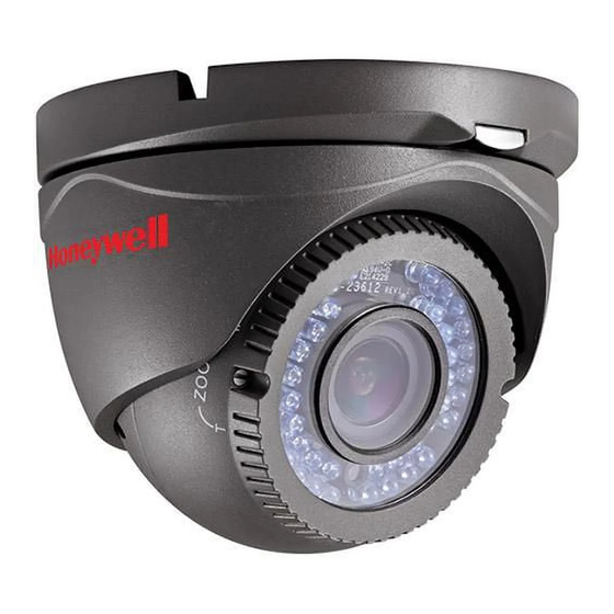
HD40H(X)/HD30H(X)/HD31H(X) Camera User Guide Overview Black Liner Lock Screw Camera Power Video Cable Cable Lower Dome Figure 1-1 Overview of HD40H(X) Camera Camera Enclosure Power Cable Mounting Base Video Cable Figure 1-2 Overview of HD30H(X) Camera 800-18605 – Rev A – 06/2014... - Page 9 HD40H(X)/HD30H(X)/HD31H(X) Camera User Guide Zoom & Focus Camera Enclosure Lock Screw Trim Ring Video Cable Power Cable Figure 1-3 Overview of HD31H(X) Camera 800-18605 – Rev A – 06/2014...
-
Page 10: Installation
HD40H(X)/HD30H(X)/HD31H(X) Camera User Guide Installation Before you start: • Make sure that the camera is in good condition and all of the assembly parts are included. • Make sure that all related equipment is powered-off during the installation. • Check that the camera specification agrees with the installation environment. - Page 11 HD40H(X)/HD30H(X)/HD31H(X) Camera User Guide Screw Hole Drilling Template Screw Hole Figure 1-4 HD40H(X) Mounting Template Figure 1-5 Disassembling the Camera Route the cables through the cable hole and connect the corresponding power and video (BNC) cables. 800-18605 – Rev A – 06/2014...
- Page 12 HD40H(X)/HD30H(X)/HD31H(X) Camera User Guide Fix the mounting base to the ceiling/wall with the supplied mounting screws. Figure 1-6 Fix the Mounting Base to the Ceiling/Wall Adjust the surveillance angle: 2). Loosen the locking screws beside the lens (see Figure 1-1). 3).
-
Page 13: Ceiling/Wall Mounting For Hd30H(X) Camera
HD40H(X)/HD30H(X)/HD31H(X) Camera User Guide Install the lower dome back to the mounting base and rotate it clockwise to secure the lower dome. Figure 1-8 Completing the Installation Ceiling/Wall Mounting for HD30H(X) Camera Steps: Drill the screws holes and the cable hole in the ceiling/wall according to the supplied mounting template. - Page 14 HD40H(X)/HD30H(X)/HD31H(X) Camera User Guide Screw Hole Figure 1-9 HD30H(X) Mounting Template Fix the mounting base to the ceiling/wall with the supplied mounting screws. Figure 1-10 Installing the Mounting Base Route the cables through the cable hole and connect the corresponding power and video (BNC) cables. 800-18605 –...
- Page 15 HD40H(X)/HD30H(X)/HD31H(X) Camera User Guide Secure the camera to the mounting base. Fix the enclosure to the camera. Figure 1-11 Installing the Camera and the Enclosure Adjust the camera position according to the figure below to get an optimum surveillance angle. 360°...
-
Page 16: Ceiling/Wall Mounting For Hd31H(X) Camera
HD40H(X)/HD30H(X)/HD31H(X) Camera User Guide Ceiling Mounting for HD31H(X) Camera Drill the screws holes and the cable hole in the ceiling/wall according to the supplied mounting template. Screw Hole Screw Hole Template Screw Hole Figure 1-13 HD31H(X) Mounting Template Loosen the locking screw, and pull the clip plate outward to disassemble the camera from the mounting base. - Page 17 HD40H(X)/HD30H(X)/HD31H(X) Camera User Guide Clip Plate Figure 1-14 Disassembling the Camera Fix the mounting base to the ceiling/wall with the supplied mounting screws. Figure 1-15 Installing the Mounting Base 800-18605 – Rev A – 06/2014...
- Page 18 HD40H(X)/HD30H(X)/HD31H(X) Camera User Guide Route the cables through the cable hole and connect the corresponding power and video (BNC) cables. Secure the camera to the mounting base by pushing the camera into base so it is held by the clips. Push the clip plate back into place and tighten the locking screw (see Figure 1-16).
- Page 19 HD40H(X)/HD30H(X)/HD31H(X) Camera User Guide 0~360° 0~75° 0~360° Figure 1-17 3-axis Angle Adjustment Use a slotted screwdriver to adjust the ZOOM screw and the FOCUS screw until you get the optimum image on the connected monitor. Figure 1-18 Zoom and Focus Adjustment 800-18605 –...
-
Page 20: Power Supply
HD40H(X)/HD30H(X)/HD31H(X) Camera User Guide Power Supply Figure 1-19 Power (12 V DC) and Video (BNC) Cable Connections Note: Please make sure that the power adapter is compatible with the camera, and the standard power supply is 12 V DC. Please refer to the camera’s technical specifications for more information. - Page 21 HD40H(X)/HD30H(X)/HD31H(X) Camera User Guide 800-18605 – Rev A – 06/2014...
- Page 22 Document 800-18605 – Rev A – 06/2014 © 2014 Honeywell International Inc. All rights reserved. No part of this publication may be reproduced by any means without written permission from Honeywell. The information in this publication is believed to be accurate in all respects.