Philips AZ1310 Service Manual
Cd soundmachine
Hide thumbs
Also See for AZ1310:
- Specifications (2 pages) ,
- User manual (1 page) ,
- Specifications (2 pages)
Table of Contents
Advertisement
CD Soundmachine
TABLE OF CONTENTS
Technical Specification & Service tools...........................2 - 1
Service Measurement......................................................2 - 2
Connections and controls.......................................3 - 1..3 - 2
Disassembly Diagram......................................................4 - 1
Block Diagram .................................................................5 - 1
Wiring Diagram ................................................................6 - 1
AF part ......................................................................7 - 1
CD part .....................................................................7 - 2
Tuner Board..............................................................7 - 3
MCU Board ..................................................................7 - 4
Cassette Board............................................................7 - 5
©
Copyright 2001 Philips Consumer Electronics B.V. Eindhoven, The Netherlands
All rights reserved. No part of this publication may be reproduced, stored in a retrieval
system or transmitted, in any form or by any means, electronic, mechanical, photocopying,
or otherwise without the prior permission of Philips.
Published by LX 0311 Service Audio
Printed in The Netherlands
Subject to modification
Cassette Board............................................................8 - 1
Main Board
Copper side .............................................................8 - 2
Component side ......................................................8 - 3
MCU Board
Copper side .............................................................8 - 4
Component side ......................................................8 - 5
Exploded view - cabinet...................................................9 - 1
Exploded view - tape deck ..............................................9 - 2
Tape deck adjustment .....................................................9 - 2
Mechanical partslist .........................................................9 - 2
Electrical partslist...........................................................10 - 1
AZ1310
all versions
CLASS 1
LASER PRODUCT
© 3140 785 32340
Advertisement
Table of Contents

Related Manuals for Philips AZ1310


Summary of Contents for Philips AZ1310
-
Page 1: Table Of Contents
LASER PRODUCT © Copyright 2001 Philips Consumer Electronics B.V. Eindhoven, The Netherlands All rights reserved. No part of this publication may be reproduced, stored in a retrieval system or transmitted, in any form or by any means, electronic, mechanical, photocopying, or otherwise without the prior permission of Philips. -
Page 2: Handling Chip Components
1 - 1 HANDLING CHIP COMPONENTS © ñ WARNING WAARSCHUWING All ICs and many other semiconductors are susceptible to Alle IC´s en vele andere halfgeleiders zijn gevoelig voor electrostatic discharges (ESD). Careless handling during electrostatische ontladingen (ESD). repair can reduce life drastically. Onzorgvuldig behandelen tijdens reparatie kan de levensduur When repairing, make sure that you are connected with the drastisch doen vermindern. -
Page 3: Specifications
2 - 1 SPECIFICATIONS GENERAL TUNER - MW SECTION Tuning range : 520 - 1602 kHz Mains voltage -/00C/05/10 230 V IF frequency : 450 kHz ± 1 kHz -/01 120/230 V Sensitivity : < 5000 µV/m at 26dB S/N Mains frequency : : 50 Hz -/00C/05/10... -
Page 4: Service Measurement
2 - 2 SERVICE MEASUREMENT Bandpass Tuner SW LF Voltmeter 250Hz-15kHz Aerial replacement e.g. PM2534 e.g. 7122 707 48001 RF Generator Capacitor e.g. PM5326 S/N and distortion meter e.g. Sound Technology ST1700B To avoid atmospheric interference all AM-measurements have to be carried out in a Faraday«s cage. Use a bandpass filter (or at least a high pass filter with 250Hz) to eliminate hum (50Hz, 100Hz). -
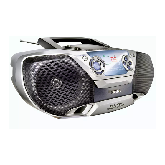
Page 5: Connections And Controls
3 - 1 CONNECTIONS AND CONTROLS CONTROL POWER SUPPLY POWER SUPPLY POWER SUPPLY BASIC FUNCTIONS TOP AND FRONT PANEL (See 1) Whenever convenient, use the AC power supply to Switching on and off and selecting function 1 LIFT TO OPEN - lift here to open CD door. 1. -
Page 6: Digital Tuner
Your set consists of materials which can be recycled if disassembled by a cleaning cassette through once. specialized company. Please observe the local regulations regarding the disposal of packaging, exhausted batteries and old equipment. For more information on operation instruction please visit Philips Audio internet site : http://www.audio.philips.com... -
Page 7: Disassembly Diagram
4 - 1 4 - 1 DISASSEMBLY DIAGRAM A. REMOVE FRONT CABINET ASSEMBLY C. REMOVE DECK MECHANISM - REMOVE SCREWS A1 (3X20) 6 PCS. - REMOVE SCREWS C5 (3X12) 6 PCS. - REMOVE SCREW A2 (3X55) 1 PC - REMOVE MAIN BOARD (INSIDE BATTERY COMPARTMENT) - REMOVE SCREWS C6 (2.5X10) 4 PCS. -
Page 8: Block Diagram
5 - 1 5 - 1 BLOCK DIAGRAM... -
Page 9: Wiring Diagram
6 - 1 6 - 1 WIRING DIAGRAM 1P UL1007 28AW WIRE 120MM BATT- BATT+ 1P UL1007 28AW WIRE 80MM BATTRY 9V (1.5X6) TRANSFORMER 3P FLAT WIRE WIRE 80MM WIRE 26AW UL1007 1PX2 TA-R 16P FFC WIRE 100MM TA-L REC-R REC-L 6P FFC WIRE 170MM... -
Page 10: Circuit Diagram Main Board Af Part
7 - 1 7 - 1 CIRCUIT DIAGRAM - MAIN BOARD (AF PART) -
Page 11: Cd Part
7 - 2 7 - 2 CIRCUIT DIAGRAM - MAIN BOARD (CD PART) -
Page 12: Tuner Board
7 - 3 7 - 3 CIRCUIT DIAGRAM - TUNER BOARD... -
Page 13: Mcu Board
7 - 4 7 - 4 CIRCUIT DIAGRAM - MCU BOARD... -
Page 14: Cassette Board
7 - 5 7 - 5 CIRCUIT DIAGRAM - CASSETTE BOARD... -
Page 15: Layout Diagram Cassette Board
8 - 1 8 - 1 LAYOUT DIAGRAM - CASSETTE BOARD 71 A 1 2729 C 5 3733 B 2 9756 C 3 72 D 5 2730 D 1 3734 D 5 9757 D 3 73 A 5 2731 C 1 3735 D 3 9759 D 4 74 A 1... -
Page 16: Copper Side
8 - 2 8 - 2 LAYOUT DIAGRAM - MAIN BOARD (COPPER SIDE VIEW) -
Page 17: Component Side
8 - 3 8 - 3 LAYOUT DIAGRAM - MAIN BOARD (COMPONENT SIDE VIEW) -
Page 18: Copper Side
8 - 4 8 - 4 LAYOUT DIAGRAM - MCU BOARD (COPPER SIDE VIEW) -
Page 19: Component Side
8 - 5 8 - 5 LAYOUT DIAGRAM - MCU BOARD (COMPONENT SIDE VIEW) - Page 20 9 - 1 9 - 1 EXPLODED VIEW DIAGRAM - CABINET SCREW LIST : M3x6 (2x) T2 x 8 T2.5 x 8 T2.5 x 10 M3x55 (1x) T3 x 8 T3 x 10 T3 x 12 T3 x 16 (2x) (6x) T3 x 20 T3 x 28...
-
Page 21: Tape Deck Adjustment
9 - 2 9 - 2 EXPLODED VIEW DIAGRAM - TAPE DECK MECHANICAL PARTSLISE - CABINET 9965 000 16875 CD DOOR SPRING 9965 000 16838 FRONT PANEL 9965 000 16849 FUNCTION KNOB ADAPTOR 9965 000 16844 COSMETIC DISC (L) 9965 000 16845 COSMETIC DISC (R) 9965 000 16843 CD TRAY... -
Page 22: Electrical Partslist
10 - 1 10 - 1 ELECTRICAL PARTSLIST ELECTRICAL PARTSLIST - MISCELLANEOUS - - DIODES - - IC & TRANSISTORS - Q601 4822 130 61311 2SA1162Y 9965 000 16396 ROD ANTENNA 6103 5322 130 34337 BAV99 Q603 9965 000 16924 2SC2712-GR 1106 9965 000 16886...