Table of Contents
Advertisement
Advertisement
Table of Contents

Related Manuals for Honda H5518H

Summary of Contents for Honda H5518H
- Page 2 The engine exhaust from this product contains chemicals known to the State defects or other reproductive harm.
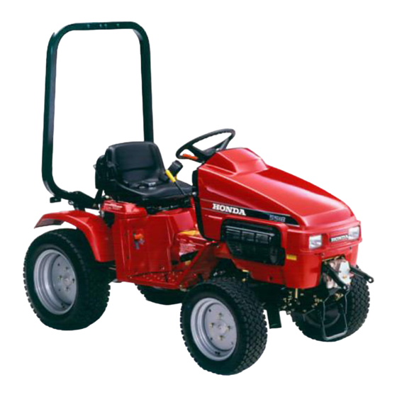
- Page 3 Thank you for purchasing This manual describes tractor, type A2. (Two Wheel Model). Information in this manual a rear hydraulic lift unit which All information in this manual available at the time of printing. Honda Motor Co., Ltd. reserves without notice and without No part of this publication...
- Page 7 Read all safety instructions ,:z’,y’“’ DTm.c*IIu I nw,* .“oI O)m.l”rul GASOLINE IS FLAMMABLE STOP ENGINE. AVOID HEAT, SPARKS.AND OPEN FLAME WHEN REFUELING. 1. SAFETY before operating. I KEEP ALL SHIELDS IN PLACE. I KEEP HANDS, FEET AND CLOTHING lOPERATE ONLY AT RECOMMENDED ,READ OWNER’S MANUAL...
- Page 8 TRACTOR SAFETY Operation of the tractor efforts on your part to ensure these requirements before SAFE OPERATING RULES Severe personal injury operation inspection operating the tractor To avoid severe personal following precautions: .All parts, epecially and securely fastened Do not remove any guards, they are installed...
- Page 9 BEFORE STARTING of heavy affect vehicle adversely that can result in severe Only use recommended Limit loads to as suggested Be extra careful Use counterweight(s) Before installing or using any attachment, and precautions. OPERATION Be sure to fasten the seat belt whenever Rollover Protective (seat belt or ROPS) without...
- Page 10 When operating the tractor face of the grade. cause the tractor to overturn. To avoid loss of control cise extreme caution Attempting to change adversely affect vehicle could result. Do not back down, To avoid loss of control surfaces. When descending a slope, can cause...
- Page 11 MAINTENANCE SAFETY Before performing thoroughly. Before cleaning, inspecting Move P.T.O. attachments. - Stop the engine Remove the spark If you hit an object, attachments. Fix any damage before Operating the tractor severe personal injury. Leaves, grass clippings, become a fire hazard. areas are kept clean.
- Page 12 SERIAL NUMBERS Record the frame and engine the serial numbers warranty inquires (see page The frame serial number engine serial number compartment). Frame serial number: Engine serial number: FRAMk NUMBER serial numbers when ordering parts, 110). is stamped on the right side of the frame. is stamped under for your reference.
- Page 13 ROLLOVER SEAT BELT HYDRAULIC LIFT LEVER HYDRAULIC CYLINDER SELECTOR IOption) DESCENT SPEED ADJUST KNOB TWO AND FOUR-WHEEL DRIVE SELECT LEVER IA4 type only1 DIFFERECTIAL LOCK PEDAL (A4 type only) CLUTCH PEDAL TRANSMISSION LEVER COMPONENT PROTECTIVE STRUCTURE (ROPSI THROTTLE LEVER STEERING ACC:LERATDR BRAKE PEDAL PEDAL...
- Page 14 ENGINE HOO[;) AIR CLEANER ENGINE OIL FILLER CAP FAN BELT SPARK PLUG CAPS HYDRAULIC SYSTEM FLUID FILLER CAP RADIATOR FRONT P.T.O.
-
Page 15: Instrument Panel
INSTRUMENT PANEL 5. PARKING BRAKE INDICATOR LIGHT 3. FUEL GAUGE 2. HEADLIGHT SWITCH 1. Engine switch Always the tractor is unattended from starting the engine. This tractor is equipped controls all the electrical Key positions: “START” “ON” “OFF” L!!!!??!!~ Do not leave the ignition when the engine is not running... - Page 16 2. Headlight switch The headlight switch (NOTlCEI or visibility Reduce speed when operating HEADLIGHT SWITCH 3. Fuel gauge The fuel gauge indicates It operates when the ignition NOTE: When the ignition indicate a faults fuel level. EMPTY When the fuel gauge needle amount of remaining...
- Page 17 4. Engine oil indicator If the oil level falls below ing, the indicator light will come If the warning light comes immediately, check the engine ed oil to bring the level to the upper the oil warning light should ly on the oil dipstick, using the tractor.
- Page 18 6. Coolant temperature The light comes on when ranae. If indicator light comes stop the engine immediately. Open the engine hood and check Check the radiator necessary (see page 91). Check fan belt. 7. Charge indicator light If this light come on when tery charging...
- Page 19 DRlVE COMPONENTS STEERING WHEE< CHOKE KNO CLUTCH PEDAL AUXILIARY TRANSMISSI LEVER MAIN TRANSMISSION LEVER REAR P.T.O. LEVER 1. Throttle lever The throttle lever controls speed); it will stay in any designated THROTTLE engine speed from SLOW position. TkiROTTLE LEVER FRONT P.T.O. CLUTCH LEVER PARKING...
- Page 20 2. Accelerator pedal (A4 type The accelerator pedal should (idle) position. Depress the foot from the pedal pedal when propelling to another. The minimum of the throttle lever. When engine speed is not lowered and can cause accident 3. Choke knob Operate the choke...
- Page 21 4. Brake pedal The brake pedal is used to slow the tractor. When you want to bring the tractor clutch pedal first, then the brake pedal. Depressing the brake cause damage to the tractor is depressed first. Driving the tractor the brake lining.
- Page 22 6. Clutch pedal Depress the clutch pedal the main transmission Wheel drive select lever or the rear P.T.O. 7. Main transmission Eight forward and four reverse and auxiliary transmission transmission lever, one of two the auxiliary lever up (higher [HIGH GEAR POS!TIONI [LOW GE 1 NOTICE Transmission...
- Page 23 8. Front P.T.O. clutch The lever is used to engage shaft. Lever in “ON” position-P.T.O. Lever in “OFF” position-P.T.O. FRONT P.T.O. LEVER When engaging the front prevent premature wear. NOTE: An interlock P.T.O. clutch lever is in the OFF position. lever or disengage the front P.T.O.
- Page 24 9. Rear P.T.O. lever The lever is used to engage The rear P.T.O. shaft rotates position and the clutch Lever in “ON” position Lever in “ON” position disengaged. Lever in “OFF” position-P.T.O. Before operating and depress the clutch NOTE: An interlock rear P.T.O.
- Page 25 11. Two- and four wheel Two and four wheel into four wheel drive, tion. For two wheel Drive position. 1 NOTICE e ore shifting plete stop and depress For oDeration of the two-and TWO AND FOUR WHEEL DRIVE SELECT LEVER 12.
-
Page 26: Lift System
HYDRAULIC LIFT SYSTEM The front attachment lift lever, when the engine NOTE: On models equipped rear attaachments can be lifted cylinder selector lever and hydraulic 1. HYDRAULIC IOptional can be raised and lowered is running. with a rear hydraulic and lowered lift lever, 2. - Page 27 1. Hydraulic cylinder The oil pressure from rear hydraulic system HYDRAULIC CYLINDER CHANGE LEVER Al ways move Leaving the lever halfway hydraulic system or interfere Observe following lever: 1. To prevent lowering knob clockwise 2. Place the lift lever in the DOWN 3.
- Page 28 2. Hydraulic lift lever The attachment can be raised and lowered SLOW UP position, position, the attachment attachment will lower ment will lower more quickly. be lowered even though stopped at its current Do not hold the lift lever in the FAST after the attachment cause damage...
- Page 29 3. Descent speed adjust Descending speed can be pre-adjusted the attachment. Adjust the ground from its highest in the FAST DOWN Thus, lighter attachments heavier attachments too much or too little selectable by the lift lever. Before adjusting the descending in NEUTRAL.
-
Page 30: Pre-Operation
PRE-OPERATION For safe and efficient before using tractor. Follow the procedures each use: 1. Park the tractor on a level surface. 2. Lock the parking brake, the front and rear P.T.O. 3. Disconnect the spark plug cap and remove tal engine start-up. - Page 31 Engine oil level Ru nning the engine damage. 1. Place the tractor on a level surface. 2. Open the hood and clean the engine the dipstick and wipe 3. Reinsert the dipstick. 4. Check the oil level level mark, fill to the upper 5.
- Page 32 Fuel level Turn the engine switch If the fuel level is low, pour gasoline the UPPER level line on the filler neck. Fuel tank capacity: 9.3 P (2.5 US gal). Gasoline is extremely treme care when handling Refuel in a well ventilated and sparks away, Gasoline...
- Page 33 Fuel recommendation Use unleaded gasoline with a pump octane rating of 86 or higher. This engine is certified to operate on unleaded gasoline. Unleaded gasoline produces fewer engine and spark plugs deposits and extends exhaust system life. Never use stale or contaminated gasoline or oil/gasoline mixture. Avoid getting dirt or water in the fuel tank.
- Page 34 Oxygenatedfuels Some conventional gasolines are being blended with alcohol or an ether compound. These gasolines are collectively referred to as oxygenated fuels. To meet clean air standardssome areas of the United Sates and Canada use oxygenated fuels to help reduce emissions. If you use an oxygenated fuel,be sure it is unleaded and meets the minimum octane rating requirement.
- Page 35 Air cleaner Check that the air cleaner ty air cleaner will restrict mance. A damaged air cleaner rapid engine wear. 1. Open the hood and remove cover and air cleaner 2. Inspect air cleaner necessary. If the air cleaner cedure described on page 85. 3.
- Page 36 Coolant If there is no coolant leaks and repair if necessary. Never remove coolant is under pressure Add coolant to the radiator level in the reserve tank after When the engine is at operating between the MIN and MAX the MIN mark, add coolant Coolant Recommendation...
- Page 37 Battery electrolyte level Open the hood, and check The electrolyte level must marks. If the electrolyte filler caps and carefully reaches the upper level line (see page 88). Batteries produce an explosion, causing away and provide adequate CHEMICAL HAZARD: tact with eyes or skin, even through Wear a faceshield...
- Page 38 Hydraulic lift system Open the hood, raise the seat, and visually oil leakage with the engine If there is any sign of cracks tractor dealer for service. Escaping hydraulic causing serious injury. running. OIL LINE Front P.T.O. belts Visually inspect the front damaged, contact...
- Page 39 Fan belt Visually inspect the fan belt for wear or damage. tact your authorized Brake pedal free play Measure Measure the brake pedal free play from fully released the brake pedal free play from fully released feel feel brake brake begin begin (0.8-...
- Page 40 Brake wear indicator Inspect brake lining condition Firmly set the parking indicator. If the wear your authorized Honda Under no circumstances brake lining is at or past the service Clutch pedal free play Measure the clutch pedal free play from fully released feel resistance.
- Page 41 Tires/wheels Check the tire pressure Turf tire pressure: AG tire pressure: Front Rear Check that the lug nuts on each wheel Torque: 13 kg-m (94 ft-lb) /TiEiEq fzv ery day, hours of operation, and retighten retighten them every Check side wall and tread excessive wear.
- Page 42 Hydraulic lift system Before performing tion) lift arms fully and confirm tractor is not equipped pushing them down by hand with DOWN position. Remove the filler cap, wipe off the dipstick is fully seated. Remove mark, add the specified Do not fill the tank beyond ed, it will result in an excessive of the fluid,...
- Page 43 Seat adjustment Make sure seat mounted. If necessary: 1. Loosen the four seat mounting 2. Move the seat to a position and comfortably. 3. Tighten the seat mounting SEAT MOUNTING BOLT (4) Steering Check the steering free play with the wheels be less than 30 mm (1.2 wheels...
-
Page 44: Parking Brake
Parking brake Make sure that the parking perly. Turn the ignition transmission lever to any position pedal and apply the parking BRAKE WARNING PARKING Headlight Turn engine switch headlight switch. HEADLIGHT brake and warning switch ON but do not start engine, (other than NEUTRAL), brake lock lever. - Page 45 Safety interlock system Before inspecting, the tractor is clear of people, This tractor is equipped the engine from being followed. Observe switches. Do not operate system, or in the operation sonal injury could result. Consult your authorized To check the system, To prevent accidental caps from the spark plugs when...
- Page 46 2. Front P.T.O. switch (I) Move sion lever to NEUTRAL, rear P.T.O. OFF. (2) Move clutch lever to ON. (3) Turn the ignition START. should not operate. (4) Move clutch lever (5) Return (ignition switch) OFF. 3. Rear P.T.O. switch (I) Move sion lever to NEUTRAL, the front...
- Page 47 4. Seat switch NOTE: make tion, it is necessary engine. Attach cap to the spark refer start, cedures described (I) Lock the parking main lever in NEUTRAL. (2) Move P.T.0; levers (3) Start the engine. (4) Move the P.T.O. of either front tachment to ON position.
- Page 48 Hydraulic lift system NOTE: To make this inspection, procedures described This inspection should tractor. The check procedure Check either, by selecting lever position. (I 1 Start the engine. (2) Set the hydraulic (3) Move the lift lever to FAST or SLOW hand from the lever.
-
Page 49: Operation
1. Starting the engine Exhaust contains cause loss of consciousness enclosed area. Be sure to provide I. Sit on the seat and check 2. Make sure the main transmission (option) and rear P.T.O. (Neutral) position. NEUTRAL FRONT P.T.O. MAIN TRANSMISSION CLUTCH LEVER 3. - Page 50 4. Turn the engine switch the key when the engine INOTlCEI Ru nning the starter the motor. If the engine fails to start, and wait at least IO seconds warms 5. As the engine position. 6. As the engine stabilizes, position.
- Page 51 2. Starting/driving Before operating understand the tractor 1. Wearing the seat belt. Wear seat operating tractor Rollover Protective attached. Use of either device ROPS) without crease chance rollover. Make sure that the seat twisted or kinked. Push the tongue plate into the buckle until it clicks.
- Page 52 2. Depress the clutch levers in the desired NOTE: When the main transmission will sound to notify the driver 3. Depress the brake pedal and place the main and auxiliary gear range for operation. lever if the parking pedal and release the parking PARKING BRtKE...
- Page 53 4. Raise the throttle Alwavs release tor in motion. Sudden vehicle control that may result suddenly or with the steering Do not rest your foot lock pedal while the tractor damage of the clutch lever slightly and slowly THROTiLE LEVER the clutch pedal slowlv starts...
- Page 54 3. How to use the differential When used properly, nient. However, improper could also damage the drive lock. The differential lock is most surface causes one of the rear wheels Operation 1. Shift the main transmission 2. With the steering wheel ferential lock pedal.
- Page 55 3. To release the differential bring the tractor to a full stop, WARD to REVERSE differential tractor on hard surfaces may overturn, causing _-- ..- [‘NOTICE .--.-..-- To avoid damage to transmission Do not apply the differential Do not rest your foot on the differential engage the differential Do not apply...
-
Page 56: Wheel Drive
4. Two and four-wheel or four wheel drive can be selected drive select lever. Prior to shifting, set the steering ing the tractor to a complete NOTE: If difficulty is encountered gears by driving the tractor engaged. We recommend that you select the two wheel according to the terrain 2-WHEEL... - Page 57 5. Turning This tractor Four carefully. Turning the tractor terrain can cause the tractor before turning. To prevent accidental Never make abrupt Slow down before Avoid sharp turns Engaging the differential to lose steering control. Be sure to raise ground rows, moldboard tachment...
- Page 58 6. Attachment limitations Use of Honda attachments limits shown below or it is not suited used do not conform Table”, they may not only endanger vent you from taking Never use attachments Never use counterweights Table. Any malfunction or damage sequence of use of attachments Attachment...
- Page 59 Max. load at lowe link end (WO) Max. weight attachment (Wl) Max. load (W21 Trailer Tongue weight (W3) Size and Weight Limits Attachment Rotary Mower 3-blade Snow Blower Snow Dozer Rotary Tiller Plow Disc Harrow Cultivator Trailer Sweeper Front end Loader Front-Mount Rotary Mower...
- Page 60 Towing Never attempt to tow anything proper hitch could cause the tractor sonal injury or equipment Never allow anyone Traveling and turning tachment is dangerous. ment over rough ground. Avoid sudden starts trailer or attachment and severe personal The weight of a trailer especially when...
- Page 61 2. Maximum tongue weight: 20 kg f 9 kg (45 Ibs + 20 Ibs) If the trailer’s load is unbalanced so that the tongue weight incorrect, the tractor may overturn resulting in severe personal injury equipment damage. NOTE: Tongue weight is the downward force that the trailer exerts on the...
- Page 62 Counterweight When an attachment is fitted front and rear wheels is lost, ning (front wheel lift, etc.). regain front-rear wheel Make suitable counterweight Under no circumstances counterweights and wheel weights precaution may endanger shorten its service life. The total number of the counterweights shown in the table...
- Page 63 Manufacture Attachment name Trailer Front-Mount HONDA 46” Rotary-Mower NOTE: In this table, the calculation counterweight is about about 20 kg (44 lb), respectively. Use of turf tires on the front mower is not recommended the equipment. Use the table below and determine tachments other than listed in the previous page.
- Page 64 2. Front Attachment number in the required. NOTE: This table is based on each counterweight ly 11 kg (25 Ibs). 600 mm 600 mm (24 in) 132 in) (133Ibs)I ’ 120 kg (267 Ibs) * Attachment should not be used. and Counterweight Table indicates...
- Page 65 7. Driving on a slope Before starting up or down ranges, so that tractor imum control. Driving across the face of a slope can cause the tractor you can be injured. Making turns on a slope can cause the tractor injured.
-
Page 66: Starting Procedure
UPHILL STARTING PROCEDURE If possible avoid stopping to stop on a hill, follow If this procedure is not followed tractor may roll backwards cause it to tip over resulting Abruptly applying down a slope may cause 1. Depress the brake 2. - Page 67 8. Stopping the engine In an emergency: Turn the engine switch (ignition switch) OFF. Depress the clutch and brake pedal. 0 In normal use: 1, Move the throttle lever to “SLOW.” 2. Depress the clutch and brake pedals simultaneously. Move the main transmission lever to “NEUTRAL”.
- Page 68 3. Shift the front and rear P.T.O. FRONT P.T.O. CLUTCH 4. Lower any attachment HYDRAULIC 5. Turn the engine key. levers LEVER REAR P.T.O. to the ground LEFT LEVER switch (ignition switch) ENGINESWITCH to the “OFF” position. LEVER with the hydraulic lift lever.
- Page 69 6. Push down the park brake lock lever while depressing the brake pedal. PARK BRAKE LOCK LEVER BRAKE’PEDAL To avoid injury to yourself and others, before leaving the trac- unattended, ALWAYS: park on level ground, disengage the power take-off (P.T.O.), lower the attachment, set the parking...
- Page 70 9. Recommended working speed Select a safe and correct operating speed as per the instructions shown the chart below. RECOMMENDED tiORI( SPEED TRAILER...
- Page 71 10. High altitude operation At high altitude, the standard carburetor air-fuel mixture will be too rich. Performance will decrease, and fuel consumption will increase. Avery rich fuel mixture may also foul the spark plugs and cause hard starting. High altitude performance can be improved by specific modifications to the carburetor.
- Page 72 TRANSPORTING Transporting engine and remain for a while ponents or the exhaust materials. Avoid touching the engine the engine has stopped. tractor. To wing the tractor another vehicle can damage Transport the tractor spillage, keep the tractor Gasoline plode, causing injury Transport the tractor...
- Page 73 3. After loading, apply (ignition switch) key. 4. Tie the tractor down Tie-down hooks should shown below. 1 NOTICE Use heavy-duty restraints the trailer. Both front outward form tractor. To avoid damaging around or near them FRONT the parking brake and remove securely.
- Page 74 INSTALLING Before installing or using and precautions. To prevent tion switch) key, and disconnect adjusting attachments. 1. Rear 3-point hitch - 1. Install the hitch Attach the check links pins and secure Install the right lower link pins. Insert the check with a lock pin.
- Page 75 UPPER LINK LOWER LINK HITCH ‘BOX 7.0 kg-m (50.6 ft-lb4 LIFT ROD PIN LINK PIN CHECK LINK PIN LOWER LINK CO&R - 2.2 kg (15.9 ft-lbsl LIFT ROD ^A.- ..-. ’ l.“I;K VIII CHECK LINK...
- Page 76 2. Rear 3-point hitch attachment Park the tractor on firm, shift lever to “N (Neutral)“. “OFF” when installing, Installing, engine running is dangerous the ignition, and disconnect Place the hydraulic “REAR”, place the lift lever in the “DOWN” position and fully the lower link.
- Page 77 f. Install the universal driven attachments) With lock on the side fully depressed, universal shaft P.T.O. hole. Release the lock, joint slowly until returns to the position in the diagram. Move the universal and forth and check lock is secure. g.
-
Page 78: Maintenance
9. MAINTENANCE The Importance of Maintenance Good maintenance is essential for safe, economical, and trouble-free opera- tion. It will also help reduce air pollution. Improper maintenance, or failure to correct a problem before operation, can cause a malfunction Always follow the inspection and maintenance recommendations schedules in this owner’s manual. - Page 79 Maintenance Safety Some of the most important safety precautions follow. However, we cannot warn you of every conceivable hazard that can arise in performing mainte- nance. Only you can decide whether or not you should perform a given task. Failure to properly follow maintenance instructionsand cause you to be seriously hurt or killed.
- Page 80 Emission Control System Source of Emissions The combustion process produces carbon monoxide, oxides of nitrogen, and hydrocarbons. Control of hydrocarbons and oxides of nitrogen is very imppr- tant because, under certain conditions, they react to form photochemical smog when subjected to sunlight. Carbon monoxide does not react in the same way, but it is toxic.
- Page 81 Problems That May Affect Emissions If you are aware of any of the following symptoms, have your engine inspected and repaired by your servicing dealer. Hard starting or stalling after starting. Rough idle. Misfiring or backfiring under load. Afterburning (backfiring). Black exhaust smoke or high fuel consumption.
- Page 82 Replacement Partss The emission control systems on your Honda engine were designed, built, and certified to conform with EPA and California emission regulations. We recom- mend the use of genuine Honda parts whenever you have maintenance done. These original-design replacement parts are manufactured to the same standards as the original parts, so you can be confident of their performance.
- Page 83 1. Tool kit The tools supplied are necessary nance, simple adjustments The tool kit is stored in the tool box behind The tool kit as well as the Owner’s tractor. for performing and repairs. the seat. Manual should i;F7 OIL FUNNEL some periodic mainte-...
-
Page 84: Maintenance Schedule
2. Maintenance schedule clutch, rear P.T.0 clutch, main transmission lever Air pressure,cracks,... - Page 85 EGULAR SERVICE PERIOD (3) EVERY EVERY FIRST EVERY EVERY EACH 3MONTHSGMONTHS YEAR 3YEARS SYEARS ITEM Perform at every indicated monthoroperatinghourinterval, SOHRS 50HRS 16OHRS 300HRS 500HRS whichever comes first. Transmissionoil NOTE: . Emission related items. (+) Replace the paper element only. (1) Service more freqently when used in dusty areas.
- Page 86 3. Engine oil change Drain oil while draining. 1. Open the engine 2. Prepare a suitable 3. Remove the oil filler cap and drain plug and drain oil into the container through the funnel. 4. Retighten the drain plug securely. 5.
-
Page 87: Air Cleaner Service
4. Air cleaner service A dirty air cleaner will restrict tractor in very dusty areas, in the MAINTENANCE Operating the engine 1. Open the engine hood. 2. Remove the wing elements and separate tears and replace if damaged. NOTE: Be sure to remove so that you can inspect 3. - Page 88 service 5. Spark plug Recommended spark Touching burns. Let the engine Spark plugs For good performance, deposits. 1. Open the engine 2. Clean any dirt from around 3. Use a spark plug wrench 4. Visually inspect the spark parent wear, or if the insulators plugs with...
- Page 89 6. Install the spark plug carefully, 7. After the spark plug is seated, press the washer. Lo ose spark Overtightening may damage NOTE: If installing plug seats to compress tighten l/8- washer. by hand, tighten with a spark plug wrench plug can get hot enough the threads.
- Page 90 6. Battery service Refilling battery fluid If the tractor is operated battery plate damage If rapid loss of electrolyte weak, causing slow authorized Honda tractor Open the engine hood and check Fill the battery with distilled battery. Batteries cause serious injury charging.
- Page 91 H Battery cleaning If the battery terminals and clean the terminals. 1. Remove battery battery 2. Disconnect the battery at the battery positive POSITIVE NEGATIVE (-1 TERMINAL 3. Remove the battery terminals with a wire Clean the battery with ing care not to get the solution tery thoroughly.
-
Page 92: Fuel Filter Change
7. Fuel filter change Gasoline is extremely Do not smoke or allow Remove the fuel filter visually inspect Replace the filter if it is contaminated Set the fuel filter in the clip with After installing a new fuel filter, make sure that the fuel hose and clip are not interferring or surrounding parts. - Page 93 8. Radiator Screen/Radiator Remove any debris from To remove: 1. Remove the right and left knob bolts. 2. Raise the both ends of the column of the slot. Then remove 3. Release the lock by pulling 4. Remove the screen radiator screen and radiator...
- Page 94 9. Transmission oil inspection Contaminated tractor’s transmission. and oil capacity. 1. Park the tractor on level ground. 2. Remove the oil check 3. The oil level should not, add oil through edge. 4. After checking, tighten Recommended oil: 1 OW-30 NOTE: If the outside...
- Page 95 10. All fasteners tightness/lubrication Check all nuts, bolts Check and apply grease Recommended Grease: points and fasteners and tighten where noted. SAE Multipurpose Grease securely if necessary.
- Page 96 Lubrication points (cont’d) Check and apply grease where noted. Recommended grease: SAE Multipurpose Grease.
- Page 97 11. Spark arrester maintenance You can purchase an optional, authorized Honda tractor areas; check local laws The muffler hot for a while after the engine while it is hot. Allow spark arrester must efficiency. 1. Remove the four 6 mm bolts 2.
- Page 98 12. Wheel remove1 Do not attempt to remove ground. Do not attempt to remove and knowledge to do so properly. 1. Apply the parking 2. Block the wheels one turn. 3. Place a jack under and raise the wheel 4. Remove the nuts and wheel.
-
Page 99: Fuse Replacement
13. Fuse replacement The fuse box is located When frequent fuse failure overload in the electrical for repair. To replace fuses pull the old fuse out of the clips with new fuse into the clips. Ne ver Serious damage to the electrical Turn the engine switch checking... -
Page 100: Headlight Bulb Replacement
14. Headlight bulb replacement Open the engine hood and lift up the edge of the bulb connector cover and pull it back. Push in and turn the bulb connector connector and bulb. Install the bulb, and then cutout in the headlight pushing it in., and then fit the rubber... -
Page 101: Long Term Storage
Preparation for storage The engine becomes very hot during after stopping. Allow Contact with a hot engine burns or fires. Let the engine The following steps should it will be stored for longer 1. Pump all gasoline container. Loosen the carburetor gasoline container. - Page 102 2. Change the engine NOTE: If the tractor engine hood, remove imately 1 oz.) of clean Turn the fan belt several Reinstall the spark plugs. FAN BELT Be sure to wear tractor has been running, before proceeding. 3. Remove the battery month.
- Page 103 4. Store the tractor on a level parking brake lever set. !3. Cover the tractor to keep out dust. 6. Check tire air pressure Removal from storage 1. Check the battery electrolyte tery, and install it in the tractor. :2. Remove the spark plugs and check that they are clean and properly (seep.
- Page 105 1~ Starter does not work; 1. Main transmission other than NEUTRAL. Front or rear PTO clutch lever set in- Loose or corroded terminal Blown fuse Battery discharged ( ENGINE 1 Engine cranks but won’t 1. No fuel in tank Choke not pulled out when engine -Pull is cold Disconnected spark piug cap -Reinstall...
- Page 106 Incorrect valve Improper grade Improper attachment Extreme weather/barometric- conditions (altitude, temperature) Parking brake Brake dragging Excessive load Clogged radiator Lack of radiator Excessive oil consumption 1. Improper oil viscosity 2. Oil leak . 3. Worn piston ring/cylinder 1 ELECTRICAL SYSTEMJ Battery runs down frequently Loose or corroded...
- Page 107 3. Faulty oil alert Headlights not turned 1. Blown light bulb Ignition key not turned 3. Blown fuse Parking brake audible 1. Blown fuse 2. Faulty buzzer Fuel gauge inoperative 1. Blown fuse 2. Faulty gauge Poor brake performance 1. Clutch pedal not depressed -Apply Excessive brake pedal play Brake linings worn...
-
Page 108: Differential Lock
pFGiiGJ Hard steering 1. Insufficient tire pressure Differential lock applied Excessive weight Uneven weight Attachments towed Steers to one side or does not track straight Incorrect brake adjustment Incorrect front-end Uneven tire pressures Loose fasteners Loose wheel nuts 1 DIFFERENTIAL LOCK 1 Differential lock not applied... - Page 109 PTO not stopped 1. Cable out of adjustment 2. PTO brake rod out of adjustment- PTO brake spring out of adjustment ___- REAR P.T.q 11” __._.__. - 0 PTO does not rotate 1. PTO lever not set in ON * PTO drive shaft cannot be installed 1.
-
Page 110: Specifications
13. SPECIFICATIONS MODEL Power product discription DIMENSION Overall length Overall width Overall height Ground clearance Wheelbase Wheel tread (Front) (Rear) Dry weight ENGINE Model Cooling system Displacement Bore and stroke Maximum horsepower Oil capacity Coolant capacity FRAME Brakes Front tire size, pressure Rear tire size, pressure Steering Fuel tank capacity... -
Page 111: Hydraulic System
Front differential oil capacity Final reduction oil capacity HYDRAULIC SYSTEM Working pressure Pump type Oil Capacity P.T.O. Rear Front Shaft Rear Front Speed Rear Front ELECTRICAL Battery Spark plug Ignition system 90 kg/cm’ (1,280 psi) Dependent of main clutch Live independent ASAE “0”... -
Page 112: Warranty Service Information
Manager can help. Almost all problems are solved in this way. If you are dissatisfied with the decision made by the dealership’s manage- ment, contact the Honda Power Equipment Customer Relations Office. You can write to: American Honda Motor Co., Inc. - Page 113 When you write or call, please provide the following information: • Model and serial numbers • Name of the dealer who sold the Honda power equipment to you • Name and address of the dealer who services your equipment •...
- Page 114 MEMO...
- Page 115 MEMO...