Table of Contents
Advertisement
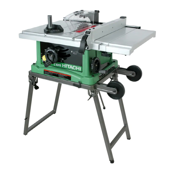
C 10FR
Model
Jobsite Table Saw
INSTRUCTION MANUAL AND SAFETY INSTRUCTIONS
WARNING
Improper and unsafe use of this power tool can result in death or serious bodily injury!
This manual contains important information about product safety. Please read and understand
this manual before operating the power tool. Please keep this manual available for others before
they use the power tool.
Advertisement
Table of Contents

Related Manuals for Hitachi C 10FR


Summary of Contents for Hitachi C 10FR
- Page 1 C 10FR Model Jobsite Table Saw INSTRUCTION MANUAL AND SAFETY INSTRUCTIONS WARNING Improper and unsafe use of this power tool can result in death or serious bodily injury! This manual contains important information about product safety. Please read and understand this manual before operating the power tool.
-
Page 2: Table Of Contents
Push Stick Pattern ..............23 Carton Contents ..............7 Parts List ................24 HITACHI AUTHORIZED SERVICE CENTERS Service under this warranty is available from Hitachi Koki U.S.A., Ltd. at : IN THE U.S.A. IN CANADA 6395 Kestrel Road Mississauga, ON L5T 1Z5 3950 Steve Reynolds Blvd. -
Page 3: Product Specifications
WARNING Some dust created by power sanding, sawing, grinding, drilling and other construction activities contains chemicals known to the state of California to cause cancer, birth defects or other reproductive harm. Some examples of these chemicals are: • Lead from lead-based paints •... -
Page 4: Power Tool Safety
POWER TOOL SAFETY WARNING Before using your table saw, it is critical that you read and understand these safety rules. Failure to follow these rules could result in serious injury or damage to the table saw. Good safety practices are a combination of common 15. -
Page 5: Table Saw Safety
TABLE SAW SAFETY ALWAYS USE SAW BLADE GUARD, splitter and anti- 12. PROVIDE ADEQUATE SUPPORT to the rear and the kickback pawls for every operation for which they can sides of the saw table for long or wide workpieces. be used, including through sawing. Through sawing operations are those in which the blade cuts 13. -
Page 6: Electrical Requirements And Safety
ELECTRICAL REQUIREMENTS AND SAFETY POWER SUPPLY REQUIREMENTS GROUNDING INSTRUCTIONS IN THE EVENT OF A MALFUNCTION OR BREAKDOWN, WARNING grounding provides a path of least resistance for electric current and reduces the risk of electric shock. This saw is equipped with an electric cord that has an equipment To avoid electrical hazards, fire hazards or damage to the grounding conductor and a grounding plug. -
Page 7: Accessories And Attachments
ACCESSORIES AND ATTACHMENTS RECOMMENDED ACCESSORIES WARNING WARNING Visit your Hardware Department or see the Power and To avoid the risk of personal injury: Hand Tools Catalog to purchase recommended Do not use adjustable (wobble) type dadoes or carbide accessories for this power tool tipped dado blades;... - Page 8 UNPACKING YOUR TABLE SAW — 8 —...
-
Page 9: Know Your Table Saw
KNOW YOUR TABLE SAW The Front of Table Saw Blade guard with LED lighting Table Insert Cutting line Rip fence Miter gauge indicator Side table extension Bevel angle Pointer & scale Extension wing Overload reset locking lever switch Miter gauge storage Blade tilting handwheel... -
Page 10: Assembly And Adjustments
ASSEMBLY AND ADJUSTMENTS ESTIMATED ASSEMBLY TIME 25~40 MINUTES Tighten all four bolts. FOLDING THE STAND (Fig. A-1) 1. Release the stand hook (1). NOTE: Do not over tighten bolts holding saw to stand. 2. Unfold the wider leg set (2). Pull the lever (3) This will damage the saw base. - Page 11 SAW MOUNTED TO WORK SURFACE (Fig. B) INSTALLING BATTERY FOR LED LIGHTING(Fig. B) 1. If the leg set will not be used, the saw must be 1. Open the cover (1) of battery box on the top of blade properly secured to a sturdy workbench using the four guard.
- Page 12 RIP FENCE (Fig. G) 3. Place the open-end wrench jaws on the flats of the 1. Lift upward on the rip fence handle (1) so that the saw arbor to keep the arbor from turning. (Fig. H) and holding clamp (2) is fully extended. place the box-end wrench (8) on the arbor nut (5), and 2.
- Page 13 BLADE GUARD ASSEMBLY (Fig. K, L, M) WARNING 1. Set the blade to maximum height and the tilt to zero degrees on the bevel scale with the hand wheels. Lock the blade lock knob. Improper splitter alignment can cause "kickback" and 2.
- Page 14 INSTALLING TABLE SIDE EXTENSIONS- cont'd (Fig. O) ADJUSTING REAR TABLE EXTENSION Snap one short location seat (5) over the end of the 1. Rear table extension should be positioned as close as rear table extension tube (3). Make sure the locating possible to the rear of the table when ripping short pin (6) in the location seat fits into the matching hole work pieces.
- Page 15 RIP FENCE INDICATOR ADJUSTMENT (Fig. Q) Fig. Q-2 The rip fence indicator (6) points to the measurement 90° 45° scale (8). The scale shows the distance from the side of the fence to nearest side of the blade. Measure the actual distance with a rule. If there is a difference between the measurement and the indicator, adjust the indicator (6).
- Page 16 BLADE PARALLEL TO THE MITER GAUGE GROOVE Additional blade adjustments (Fig. S) (Fig. R, S) The adjusting mechanism is located on top of blade height adjusting hand wheel under the tabletop. If the front and WARNING rear measurements are not the same, adjust the alignment by the mechanism as follows: If the blade is partial to right side: This adjustment was made at the factory, but it should be...
-
Page 17: Operation
OPERATION OVERLOAD PROTECTION (Fig. U) BASIC SAW OPERATIONS This saw has an overload relay button (3) that resets the RAISE THE BLADE (Fig. T) motor after it shuts off due to overloading or low voltage. To raise or lower the blade, turn the blade elevation If the motor stops during operation, turn the ON / OFF handwheel (1) to the desired blade height, and then switch to the OFF position. - Page 18 CUTTING OPERATIONS Fig. W There are two basic types of cuts: ripping and crosscutting. Ripping is cutting along the length and the grain of the workpiece. Crosscutting is cutting either across the width or across the grain of the workpiece. Neither ripping nor crosscutting may be done safely freehand.
- Page 19 BEVEL RIPPING Fig. Y This cut is the same as ripping except the blade bevel angle is set to an angle other than "0". WARNING Cut only with the workpiece and the fence on the right side of the blade. RIPPING SMALL PIECES WARNING Avoid injury from the blade contact.
- Page 20 MITERING (Fig. BB) Fig. CC-1 This sawing operation is the same as crosscutting except 30" the miter gauge is locked at an angle other than 90 1. Hold the workpiece (2) firmly against the miter 2-5/8" gauge (3). 2. Feed the workpiece slowly into the blade (1) to 3/4"...
-
Page 21: Maintenance
All electrical or mechanical repairs should be attempted gum, pitch, and other contaminants for smooth operation. only by a trained repair technician. Contact Hitachi Authorized Service Center for service. Use only identical If excessive looseness is observed in any parts of the replacement parts. -
Page 22: Troubleshooting Guide
To avoid injury from an accidental start, turn the switch OFF and always remove the plug from the power source before making any adjustments. Consult Hitachi Authorized Service Center if for any reason the motor will not run. SYMPTOM POSSIBLE CAUSES... -
Page 23: Push Stick Pattern
— 23 —... -
Page 24: Parts List
PARTS LIST 10" JOB SITE TABLE SAW MODEL NO. C10FR Always order by I.D. Number PARTS LIST FOR SCHEMATIC A I.D. Description Size I.D. Description Size I.D. Description Size 2178 E X T E N T ION W IN G 0J 8D FLAT W AS HE R 3/8* 3/4-5/64 1... - Page 25 10" JOB SITE TABLE SAW MODEL NO. C10FR — —...
- Page 26 10" JOB SITE TABLE SAW MODEL NO. C10FR I.D. Description Size I.D. Description Size 27DJ FOAM 01AD WING NUT 27DL HANDLE 01AE LEVELING PAD 27DM BRACKET ASS'Y (RIGHT) 0J4E FLAT WASHER ø6*13-1 27DV LEVELING PAD 0J4F FLAT WASHER ø8X16-2.5 27DW DUST COLLECTOR ASS'Y 0JAZ WAVE WASHER WW-6 27DY COUPLING...
- Page 27 — 27 —...
- Page 28 Issued by Hitachi Koki Co., Ltd. Sinagawa Intercity Tower A, 15-1, Konan 2-chome, Minato-ku, Tokyo 108-6020, Japan Distributed by Hitachi Koki U.S.A., Ltd. 3950 Steve Reynolds Blvd. Norcross, GA 30093 Hitachi Koki Canada Co. 6395 Kestrel Road Mississauga ON L5T 1Z5 Code No.