Hitachi C 10FR Instruction Manual
Jobsite table saw
Hide thumbs
Also See for C 10FR:
- Instruction manual and safety instructions (28 pages) ,
- User manual (72 pages)
Table of Contents
Advertisement
Model
INSTRUCTION MANUAL AND SAFETY INSTRUCTIONS
Improper and unsafe use of this power tool can result in death or serious bodily injury!
This manual contains important information about product safety. Please read and understand this manual
before operating the power tool. Please keep this manual available for others before they use the power
tool.
N136
C 10FR
OFF
ON
WARNING
– 1 –
Jobsite Table Saw
English
Hitachi Koki
Advertisement
Table of Contents

Related Manuals for Hitachi C 10FR


Summary of Contents for Hitachi C 10FR
- Page 1 English Model Jobsite Table Saw C 10FR INSTRUCTION MANUAL AND SAFETY INSTRUCTIONS WARNING Improper and unsafe use of this power tool can result in death or serious bodily injury! This manual contains important information about product safety. Please read and understand this manual before operating the power tool.
-
Page 2: Table Of Contents
English CONTENTS English SECTION PAGE Product Specifications ........................ Power Tool Safety ........................Table Saw Safety ........................Electrical Requirements and Safety ................... Accessories and Attachments ....................Tools Needed for Assembly ....................... Carton Contents ......................... Know Your Table Saw ........................ Assembly and Adjustments ......................Operation ............................ -
Page 3: Product Specifications
English WARNING Some dust created by power sanding, sawing, grinding, drilling and other construction activities contains chemicals known to the state of California to cause cancer, birth defects or other reproductive harm. Some examples of these chemicals are: • Lead based paints •... -
Page 4: Power Tool Safety
English POWER TOOL SAFETY WARNING Before using your table saw, it is critical that you read and understand these safety rules. Failure to follow these rules could result in serious injury or damage to the table saw. Good safety practices are a combination of common accessories. -
Page 5: Table Saw Safety
English TABLE SAW SAFETY 1. ALWAYS USE SAW BLADE GUARD, splitter 12. PROVIDE ADEQUATE SUPPORT to the rear and antikickback pawls for every operation for and the sides of the saw table for long or wide which they can be used, including through sawing. workpieces. -
Page 6: Electrical Requirements And Safety
English ELECTRICAL REQUIREMENTS AND SAFETY CONNECTING TO THE POWER SUPPLY Check that the power supply and plug used is in accordance with your drill press. Have a look at the rating plate of the motor or the rating on the drill press. Any changes should always be carried out by a qualified electrician. WARNING This machine must be earthed. -
Page 7: Accessories And Attachments
English ACCESSORIES AND ATTACHMENTS RECOMMENDED ACCESSORIES WARNING WARNING To avoid the risk of personal injury: • Do not use a dado with a diameter larger than 6” Visit your Hardware Department or see the Power (152.4mm). and Hand Tools Catalog to purchase recommended •... - Page 8 English UNPACKING YOUR TABLE SAW – 8 –...
-
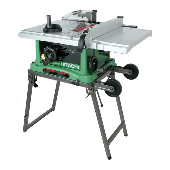
Page 9: Know Your Table Saw
English KNOW YOUR TABLE SAW The Front of Table Saw Blade guard with LED lighting Table Insert Rip fence Cutting line indicator Miter gauge Side table extension Bevel angle pointer & scale Overload reset switch Extension wing locking lever Miter gauge storage Blade tilting handwheel Fence storage Blade bevel lock knob... -
Page 10: Assembly And Adjustments
English ASSEMBLY AND ADJUSTMENTS ESTIMATED ASSEMBLY TIME 25~40 MINUTES NOTE: Do not over tighten bolts holding saw to stand. This will damage the saw base. FOLDING THE STAND (FIG. A-1) 5. Carefully set the saw in its upright position on a 1. - Page 11 English SAW MOUNTED TO WORK SURFACE (FIG. B) INSTALLING BATTERY FOR LED LIGHTING SPACE 1. If the leg set will not be used, the saw must be (FIG. D) properly secured to a sturdy workbench using the 1. Open the cover (1) of battery box on the top of blade four mounting holes at the base of the saw.
- Page 12 English RIP FENCE (FIG. G) 4. Remove the arbor nut (5) and flange (6), remove 1. Lift upward on the rip fence handle (1) so the rear blade. holding clamp (2) is fully extended. 5. Install the saw blade onto the arbor with the BLADE 2.
- Page 13 English BLADE GUARD ASSEMBLY (FIG. K, L, M) WARNING 1. Set the blade to maximum height and the tilt to zero degrees on the bevel scale with the handwheels. Improper splitter alignment can cause “kickback” and Lock the blade lock knob. serious injury.
- Page 14 English ADJUSTING REAR TABLE EXTENSION INSTALLING TABLE SIDE EXTENSIONS- cont’d (FIG. O) 1. Rear table extension should be positioned as close 6. Snap one short location seat (5) over the end of the rear table extension tube (3). Make sure the locating as possible to the rear of the table when ripping short workpieces.
- Page 15 English RIP FENCE INDICATOR ADJUSTMENT (FIG. Q) Fig. Q-2 1. The rip fence indicator (6) points to the measurement 90° 45° scale (8). The scale shows the distance from the side of the fence to nearest side of the blade. 2.
- Page 16 English BLADE PARALLEL TO THE MITER GAUGE GROOVE 4. Tighten the nuts (1) and the left screw and (FIG. R, S) remeasure, as described in steps 4 to 9 in the prior section. 5. Recheck blade clearance making sure that the WARNING blade does not hit the table insert or other parts when at the 90°...
-
Page 17: Operation
English OPERATION BASIC SAW OPERATIONS OVERLOAD PROTECTION (FIG. W) RAISE THE BLADE (FIG. U) This saw has an overload relay button (3) that resets the To raise or lower the blade, turn the blade elevation motor after it shuts off due to overloading or low voltage. handwheel (1) to the desired blade height, and then If the motor stops during operation, turn the ON / OFF tighten the bevel lock knob (2) to maintain the desired... - Page 18 English CUTTING OPERATIONS WARNING There are two basic types of cuts: ripping and crosscutting. Ripping is cutting along the length and the AVOID KICKBACK by pushing forward on the section grain of the workpiece. Crosscutting is cutting either of the workpiece that passes between the blade and the across the width or across the grain of the workpiece.
- Page 19 English BEVEL RIPPING with the proper operation of the sawblade guard. When This cut is the same as ripping except the blade bevel cutting long workpieces, you can make a simple outfeed angle is set to an angle other than “0°”. support by clamping a piece of plywood to a sawhorse.
- Page 20 English side groove because the bevel angle may cause the blade guard to interfere with the cut if used on the Fig. EE left side groove. 1. Set the miter gauge (3) to the desired angle. 2. Place the miter gauge in the right side groove of the table.
-
Page 21: Maintenance
All electrical or mechanical repairs should be attempted If excessive looseness is observed in any parts of the only by a trained repair technician. Contact Hitachi blade raising mechanism or tilting mechanism, contact Authorized Service Center for service. Use only identical Hitachi Authorized Service Center immediately. -
Page 22: Troubleshooting Guide
To avoid injury from an accidental start, turn the switch OFF and always remove the plug from the power source before making any adjustments. • Consult Hitachi Authorized Service Center if for any reason the motor will not run. SYMPTOM... -
Page 23: Push Stick Pattern
English PUSH STICK CONSTRUCTION ● This is a full-size drawing (actual size) ● Use good quality plywood or solid wood ● Use 1/2 in. or 3/4 in. material ● Push stick MUST be thinner than the width of material being cut Drill Hole For Hanging Notch To Prevent... -
Page 24: Parts List
English PARTS LIST 10” (255mm) JOBSITE TABLE SAW MODEL NO. C10FR PARTS LIST FOR SCHEMATIC Always order by I.D. Number Parts No. I.D. Description Size QTY Parts No. I.D. Description Size 726434 08VH CORD CLAMP 726587 0KFG CR. RE. PAN HD. SCREW M5*0.8-12 726437 09JK... - Page 25 English 10” (255mm) JOBSITE TABLE SAW MODEL NO. C10FR – 25 –...
- Page 26 English 10” (255mm) JOBSITE TABLE SAW MODEL NO. C10FR PARTS LIST FOR STAND Parts No. I.D. Description Size QTY Parts No. I.D. Description Size 726357 01AD WING NUT 726765 27DL HANDLE 726358 01AE LEVELING PAD 726766 27DM BRACKET ASS’Y (RIGHT) 726477 0J4E FLAT WASHER...
- Page 27 English – 27 –...
- Page 28 English Issued by Hitachi Koki Co., Ltd. Shinagawa Intercity Tower A, 15-1, Konan 2-chome, Minato-ku, Tokyo 108-6020, Japan Code No. C99135011 Printed in Taiwan – 28 –...