Honeywell PRO TH3210D Installation Manual
Non-programmable digital thermostat
Hide thumbs
Also See for PRO TH3210D:
- Manual (17 pages) ,
- Operating manual (56 pages) ,
- Installation manual (25 pages)
Table of Contents
Advertisement
Quick Links
Advertisement
Table of Contents

Related Manuals for Honeywell PRO TH3210D


Summary of Contents for Honeywell PRO TH3210D
-
Page 1: Installation Guide
Installation Guide TH3210D Non-programmable Digital Thermostat... -
Page 2: Power Type
If this product is replacing a control that contains mercury in a sealed tube, do not place the old control in the trash. Contact your local waste management authority for instructions regarding recycling and proper disposal. ® U.S. Registered Trademark. Patents pending. Copyright © 2005 Honeywell International Inc. All rights reserved. -
Page 3: Table Of Contents
PRO TH3210D Non-programmable Digital Thermostat Table of contents I I n n s s t t a a l l l l a a t t i i o o n n A A p p p p e e n n d d i i c c e e s s Pre-installation checklist ....2... -
Page 4: Pre-Installation Checklist
Installation Guide Pre-installation checklist Package contents Check to make sure your package includes the following items: • PRO TH3210D digital thermostat (wallplate attached to back) • Operating manual • Wall anchors and mounting screws (2 each) • AA alkaline batteries (2) Required tools &... -
Page 5: Wallplate Installation
PRO TH3210D Non-programmable Digital Thermostat Wallplate installation Grasp top and bottom of wallplate Remove the wallplate from the ther- and pull to remove from thermostat. mostat as shown at left, then follow directions below for mounting. 1 Pull wires through wire hole. -
Page 6: Wiring
Installation Guide Wiring CAUTION: ELECTRICAL HAZARD. Can cause electrical shock or equipment damage. Disconnect power before wiring. Wiring Keep wires in this shaded area 1 Loosen screw terminals, insert wires into terminal block, then re- tighten screws. 2 Push excess wire back into the wall opening. -
Page 7: Wiring Diagrams
PRO TH3210D Non-programmable Digital Thermostat Wiring diagram Power supply. Provide disconnect means and overload protection as required. Optional 24 VAC common connection. Use either O or B terminals for changeover valve. L terminal is powered continuously when thermostat is set to Em Heat. -
Page 8: Battery Installation
Installation Guide Power options & mounting AC Power The thermostat can be powered by 24 VAC power, or by batteries. To wire the thermostat for AC power, connect the common side of the Connect common transformer to the “C” terminal as side of transformer shown at left. -
Page 9: Installer Setup
PRO TH3210D Non-programmable Digital Thermostat Installer setup Follow the procedure below to configure the thermostat to match the installed heating/cooling system, and customize feature operation as desired. Press and hold both buttons Function Setting number Setup To begin, press and hold the... -
Page 10: System Test
Installation Guide Installer system test Follow the procedure below to test the heating and cooling system. System test System status number Test System switch 1 Set S S Y Y S S T T E E M M switch to Heat. 2 Press to turn on and check systems (see table, below). -
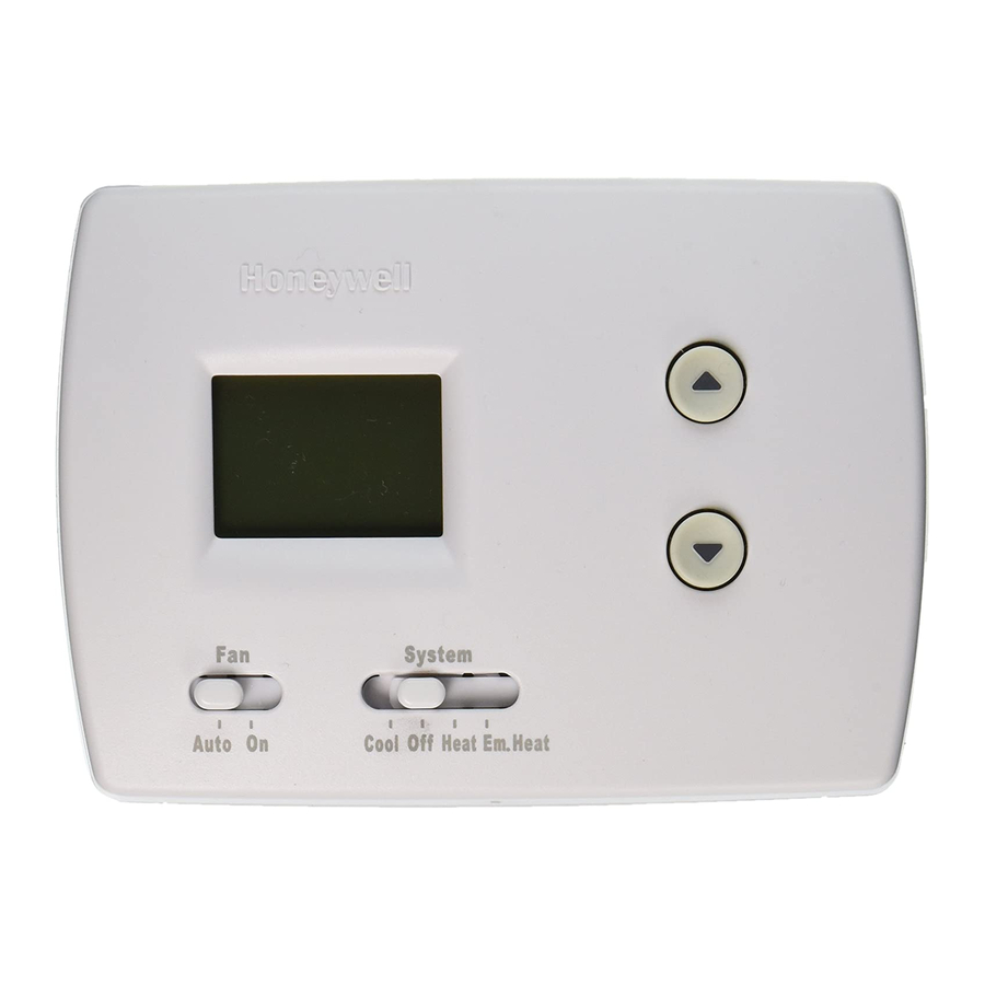
Page 11: Quick Reference To Controls
PRO TH3210D Non-programmable Digital Thermostat Quick reference to controls Digital display screen Temperature buttons Press to adjust temperature settings System switch • Cool: Thermostat controls only the cooling system. • Heat: Thermostat controls only the heating system. • Off: Heating and cooling systems are off. -
Page 12: In Case Of Difficulty
Installation Guide In case of difficulty If you have difficulty with your thermostat, please try the suggestions below. Most problems can be corrected quickly and easily. Display is blank • Check circuit breaker and reset if necessary. • Make sure heating & cooling power switches are on. •... -
Page 13: Accessories
PRO TH3210D Non-programmable Digital Thermostat Accessories Please contact your distributor to order accessories. Cover plate assembly ..........Part Number 50002883-001 (Used to cover marks left by old thermostats.) Specifications Temperature Ranges Electrical Ratings • Heat: 40° to 90°F (4.5° to 32°C) •... - Page 16 35 Dynamic Drive Golden Valley, MN 55422 Scarborough, Ontario M1V 4Z9 http://yourhome.honeywell.com Printed in U.S.A. on recycled paper containing at least 10% post-consumer paper fibers. ® U.S. Registered Trademark. © 2005 Honeywell International Inc. Patents pending. All rights reserved. 69-1775 • 06-2005...