Table of Contents
Advertisement
Advertisement
Chapters
Table of Contents

Related Manuals for Makita G1700I


Summary of Contents for Makita G1700I
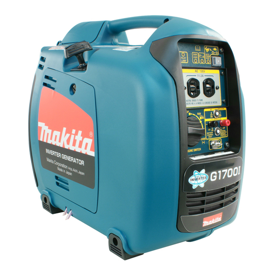
- Page 1 GENERATOR MODEL 3ZZ9990147 ÉJÉi É_...
- Page 2 STOP STOP CHOKE CHOKE STOP CHOKE STOP AUTO POWER SAVE CHOKE OVER LOAD PILOT LAMP...
- Page 3 EPA regulations during its warranty period. For the components listed under PARTS COVERED, the Makita Factory Service Center or Service Center authorized by MAKITA will, at no cost to you, make the necessary diagnosis, repair, or replacement necessary to ensure that the engine complies with applicable U.S. EPA regulations.
- Page 4 HOW TO MAKE A CLAIM All repair qualifying under this limited warranty must be performed by a Makita Factory Service Center or Service Center authorized by MAKITA . In the event that any emission-related part is found to be defective during the warranty period, you shall notify Makita Warranty Department at 1-800-4-MAKITA and you will be advised of the appropriate warranty service dealer or service providers where the warranty repair can be performed.
-
Page 5: Table Of Contents
This manual covers operation and maintenance of the MAKITA GENERATOR. This MAKITA GENERATOR can be used for general electrical equipments, appliances, lamps, tools as an AC power source. With regards to DC application, the terminals are used only for charging 12 volt battery. -
Page 6: Safety Precautions
1. SAFETY PRECAUTIONS Please make sure you review each precaution carefully. Pay special attention to statement preceded by the following words. WARNING “WARNING” indicates a strong possibility of severe personal injury or loss of life if instructions are not followed. CAUTION “CAUTION”... - Page 7 WARNING Do not operate in rain, in wet or damp conditions, or with wet hands. The operator may suffer severe electric shock if the generator is wet due to rain or snow. WARNING If wet, wipe and dry it well before starting. Do not pour water directly over the generator, nor wash it with water.
-
Page 8: Rated Frequency Hz
Symbols and Meanings In accordance with the European requirements (eec Directives),the specified symbols as shown in the following table are used for the products and this instruction manual. Fire, open light and smoking Read the operator's instruction manual. prohibited. Stay clear of the hot surface. Caution, risk of electric shock. -
Page 9: Components
2. COMPONENTS (See Fig. 1 1 ) When the engine stops due to oil shortage, it can NOTE not be started anymore even by pulling the start Please refer to the illustrations on the back page of knob (just the alarm lamp flickers). In such a case, the front cover or back cover for Fig. -
Page 10: Pre-Operation Checks
4. PRE-OPERATION CHECKS (See Fig. 3 3 ) 7. DC TERMINALS (See Fig. 2 2 -t t ) 1. CHECK ENGINE OIL (See Fig. 3 3 -q q ,w w ) DC electric power for battery charge is available. - Red is positive (+) terminal. Before checking or refilling oil, be sure generator is - Black is negative (-) terminal. -
Page 11: Operating Procedures
If such grounding conductor or grounding WARNING electrode is unavailable, connect the Make sure you review each warning in grounding lug of the generator to the order to prevent fire hazard. grounding terminal of the using electric tool or Do not refill tank while engine is appliance. -
Page 12: Control Panel
(f) Make sure the pilot lamp is on. This indicates that the generator is properly operating. NOTE Please consult with the Makita factory or authorized service center if the pilot lamp is turned off during the proper operation. 2. USING ELECTRIC POWER WARNING Make sure that the appliance is switched OFF before connecting it to the generator. - Page 13 SAFETY PRECAUTIONS WHILE CHARGING WARNING An explosive hydrogen gas is discharged Be sure to ground the generator if the through vent holes in the battery during the connected electrical device is grounded. charging process. Do not allow spark or open Failure to ground unit could lead to flame around the generator or battery during the electrical spark.
-
Page 14: Wattage Information
6. WATTAGE INFORMATION Some appliances need a "surge" of energy when starting. This means that the amount of electrical power needed to start the appliance may exceed the amount needed to maintain its use. Electrical appliances and tools normally come with a label indicating voltage, cycles / Hz, amperage (amps) and electrical power needed to run the appliance or tool. -
Page 15: Spark Arrester
7. SPARK ARRESTER In a dry or wooded area, it is recommendable to use the product with a spark arrester. Some areas require the use of a spark arrester. Please check your local laws and regulations before operating your product. The spark arrester must be cleaned regularly to keep it functioning as designed. -
Page 16: Maintenance Schedule
8. MAINTENANCE SCHEDULE MAINTENANCE, REPLACEMENT OR REPAIR OF THE EMISSION CONTROL DEVICES AND SYSTEMS MAY BE PERFORMED BY ANY NONROAD ENGINE REPAIR ESTABLISHMENT OR INDIVIDUAL. DAILY INSPECTION Before running the generator, check the following service items: Safe surroundings Leakage of gasoline and engine oil Enough clean engine oil AC and DC terminals for damage Enough gasoline... -
Page 17: [Approx.] Hours
Do not pour it down into sewage drains, onto garden soil or into open streams. Your local zoning or environmental regulations will give you more detailed instructions on proper disposal. *Note: 2. As to the procedures for these items, please refer to the SERVICE MANUAL or consult your nearest Makita service dealer. -
Page 18: How-To" Maintenance
9. "HOW-TO" MAINTENANCE (See Fig. 5 5 ) 3. CLEANING AND ADJUSTING SPARK PLUG (See Fig. 5 5 -e e ,r r ) CAUTION q SPARK PLUG Make sure the engine is stopped before w PLUG WRENCH starting any maintenance, servicing or repair. -
Page 19: Transporting
11. TRANSPORTING CAUTION When transporting the generator, make sure that the fuel (gasoline) should be drained from the Do not place any heavy objects on the tank. generator. Select and place the generator in the WARNING proper position of the transport vehicle so that the generator not be moved or To prevent fuel spillage due to the fallen down. -
Page 20: Troubleshooting
When generator engine fails to start after several attempts, or if no electricity is available at the output socket, check the following chart. If your generator still fails to start or generate electricity, contact your nearest Makita factory or authorized service center for further information or corrective procedures. When Engine Fails to Start: Check if engine switch is in its proper position. -
Page 21: Specifications
14. SPECIFICATIONS MODEL G1700I Type Multipole revolving field invertor type AC Output Rated voltage V Rated Frequency Rated current 11.2 Rated output 1.35 Rated power factor Safety device ; type Electoronic and Current breaker DC Output Rated voltage V Rated current Safety device ;... -
Page 22: Wiring Diagram
15.WIRING DIAGRAM G1700I (60Hz-120V) ENGINE CONTROL PANEL LED INDICATOR AC CIRCUIT BRAKER STEP MOTOR AC RECEPTACLE IGNITION INVERTER & AUTO POWER COIL SAVE SWITCH ENGINE CONTROL UNIT PICKUP COIL OIL LEVEL SENSOR ENGINE SWITCH EARTH PLATE Grn/Y EARTH (GROUND) TERMINAL... - Page 24 ISSUE EMD-GU1979 Makita Corporation 3-11-8, Sumiyoshi-cho Anjo, Aichi 446-8502 Japan PRINTED IN JAPAN December 2004...