Hitachi B16RM Instruction Manual And Safety Instructions
Drill press
Hide thumbs
Also See for B16RM:
- Safety and instruction manual (64 pages) ,
- Instruction and safety manual (21 pages) ,
- Instruction manual and safety instructions (48 pages)
Table of Contents
Advertisement
B 16RM
Model
Drill Press
INSTRUCTION MANUAL AND SAFETY INSTRUCTIONS
WARNING
Improper and unsafe use of this power tool can result in death or serious bodily injury!
This manual contains important information about product safety. Please read and understand
this manual before operating the power tool. Please keep this manual available for others before
they use the power tool.
Advertisement
Table of Contents

Related Manuals for Hitachi B16RM


Summary of Contents for Hitachi B16RM
- Page 1 B 16RM Model Drill Press INSTRUCTION MANUAL AND SAFETY INSTRUCTIONS WARNING Improper and unsafe use of this power tool can result in death or serious bodily injury! This manual contains important information about product safety. Please read and understand this manual before operating the power tool. Please keep this manual available for others before they use the power tool.
-
Page 2: Table Of Contents
Know Your Drill Press ............9 Parts list ................. 22 Glossary of Terms ..............10 HITACHI AUTHORIZED SERVICE CENTERS Service under this warranty is available from Hitachi Koki U.S.A., Ltd. at : IN THE U.S.A. IN CANADA 6395 Kestrel Road Mississauga, ON L5T 1Z5 3950 Steve Reynolds Blvd. -
Page 3: Product Specifications
WARNING Some dust created by power sanding, sawing, grinding, drilling and other construction activities contains chemicals known to the state of California to cause cancer, birth defects or other reproductive harm. Some examples of these chemicals are: Lead from lead-based paints Crystalline silica from bricks, cement and other masonry products Arsenic and chromium from chemically treated lumber Your risk from these exposures varies, depending on how often you do this type of work. -
Page 4: Safety
SAFETY 13. REMOVE ADJUSTING KEYS AND WRENCHES. Form GENERAL SAFETY INSTRUCTIONS habit of checking to see that keys and adjusting BEFORE USING THIS DRILL PRESS wrenches are removed from the tool before turning it Safety is a combination of common sense, stay alert and knowing how to use your drill press. -
Page 5: Drill Press
13. SECURE THE WORK. Use clamps or a vise to hold the SPECIFIC SAFETY INSTRUCTIONS FOR THE work when practical. It’s safer than using your hand DRILL PRESS and it frees both hands to operate tool. 14. MAKE SURE all clamps and locks are firmly tightened WARNING before drilling. -
Page 6: Grounding Instructions
FIGURE A shows a 3-prong electrical plug and receptacle GROUNDING INSTRUCTIONS that has a grounding conductor. If a properly grounded IN THE EVENT OF A MALFUNCTION OR BREAKDOWN, receptacle is not available, an adapter (FIGURE B) can be grounding provides a path of least resistance for electric used to temporarily connect this plug to a 2-contact current and reduces the risk of shock. -
Page 7: Accessories And Attachments
ACCESSORIES AND ATTACHMENTS RECOMMENDED ACCESSORIES WARNING WARNING Use only accessories designed for this drill press to avoid injury from broken parts or thrown workpieces. Use only accessories recommended for this drill press. Follow the instructions that accompany the accessories. You may recommend other accessories not listed in this Use of improper accessories may cause hazards. - Page 8 CARTON CONTENTS —8 —...
-
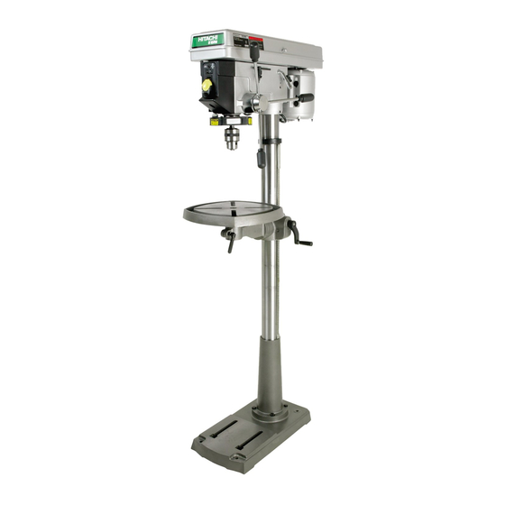
Page 9: Know Your Drill Press
KNOW YOUR DRILL PRESS Cover knob Belt guard cover Belt pulleys Belt tension handle Light switch Belt tension lock knob Belt tension knob ON/OFF switch Feed handles Head locking set screws Chuck Upper stop nut Laser guide Column collar Lower stop nut Depth scale Depth stop Stop nut... -
Page 10: Glossary Of Terms
GLOSSARY OF TERMS BASE – Supports drill press. For additional stability, holes DRILL ON/OFF SWITCH – Has a locking feature. This are provided in base to bolt drill press to floor. feature is intended to help prevent unauthorized and possible hazardous use by children and others. Insert the BACKUP MATERIAL –... -
Page 11: Assembly And Adjustment
ASSEMBLY AND ADJUSTMENTS ESTIMATED ASSEMBLY TIME 20~40MINUTES ASSEMBLY INSTRUCTIONS Fig. B WARNING For your own safety, never connect plug to power source outlet until all assembly and adjustment steps are completed, and you have read and understood the safety and operating instructions. TOOLS NEEDED Slotted screwdriver 8"... - Page 12 INSTALLING THE HEAD (Fig. D) INSTALLING THE CHUCK (Fig. G, H and I) WARNING WARNING The Drill Press head is very heavy and MUST be lifted Before any assembly of the chuck and arbor to the drill with the help of 2 PEOPLE OR MORE to safely assemble press head, clean all mating surfaces with a non- the Drill Press head on the column.
- Page 13 Using a rubber mallet, plastic-tipped hammer, or a DRILL PRESS ADJUSTMENTS block of wood and a hammer, firmly tap the chuck CAUTION: All the adjustments for the operation of the drill upward into position on the spindle shaft. press have been completed at the factory. Due to normal Fig.
- Page 14 SPINDLE / QUILL (Fig. N) Fig. O Rotate the feed handles counterclockwise to lower spindle to its lowest position. Hand support the spindle securely and move it back and forth around the axis. If there is Hub Assembly play, do the following: Loosen the lock nut (1).
-
Page 15: Operation
THE LASER -TRAC™ ADJUSTING THE LASER LINES (Fig. Q-1) Your tool is equipped with our latest innovation, the Laser A. How to check the Laser-beam Alignment? -Trac™, a battery powered device using Class II laser Adjust the table height so it is 7 inches below the beams. - Page 16 ON / OFF SWITCH PANEL (Fig. S) INSTALLING A DRILL BIT IN THE CHUCK (Fig. T) The “ON / OFF” switch has a removable, yellow plastic With the switch “OFF” and the yellow switch key key. With the key removed from the switch, unauthorized removed, open the chuck jaws (1) using the chuck key and hazardous use by children and others is minimized.
- Page 17 DRILLING TO A SPECIFIC DEPTH (Fig. V) Fig. W Drilling a blind hole (not all the way through workpiece) to a given depth can be done two ways: Workpiece method Mark the depth (1) of the hole on the side of the workpiece.
- Page 18 Use the SPINDLE SPEED recommended for the BASIC OPERATION INSTRUCTIONS specific operation and workpiece material. Check To get the best results and minimize the likelihood of the panel on the inside pulley cover or the chart personal injury, follow these instructions for operating below for drilling speed information.
- Page 19 POSITIONING THE TABLE AND WORKPIECE (Fig. Y and Z) TILTING THE TABLE (Fig. AA) Lock the table (1) to the column (2) at a position so the NOTE: The table arm and support (1) has a predrilled hole tip of the drill bit (3) is just above the top of the with a locking set screw inserted for locking the table into workpiece (4).
-
Page 20: Maintenance
MAINTENANCE MAINTAINING YOUR DRILL PRESS WARNING For your own safety, turn the switch “OFF” and remove the plug from the power source outlet before maintaining or lubricating your drill press. Frequently blow out, using an air compressor or dust vacuum, any dust that accumulates inside the motor. A coat of automotive paste wax applied to the table and column will help to keep the surface clean &... -
Page 21: Troubleshooting
To avoid injury from an accidental start, turn the switch “OFF” and always remove the plug from the power source before making any adjustment. Consult Hitachi Authorized Service Center if for any reason the motor will not run. PROBLEM POSSIBLE CAUSES... -
Page 22: Parts List
PARTS LIST 15" DRILL PRESS MODEL NO. B16RM Always order by I.D. Number. PARTS LIST FOR SCHEMATIC A I.D. Description Size I.D. Description Size 04A4 CLAM P-COR D 0J K H V-B E LT 04Q4 S T ICK E R 0J Q0 HE X . - Page 23 15" DRILL PRESS MODEL NO. B16RM — —...
- Page 24 Issued by Hitachi Koki Co., Ltd. Sinagawa Intercity Tower A, 15-1, Konan 2-chome, Minato-ku, Tokyo 108-6020, Japan Distributed by Hitachi Koki U.S.A., Ltd. 3950 Steve Reynolds Blvd. Norcross, GA 30093 Hitachi Koki Canada Co. 6395 Kestrel Road Mississauga ON L5T 1Z5 Code No.