HP Compaq 6005 Pro Business PC Maintenance & Service Manual
Business pc
Hide thumbs
Also See for Compaq 6005 Pro Business PC:
- Maintenance and service manual (155 pages) ,
- Hardware reference manual (62 pages) ,
- Specification (57 pages)
Table of Contents
Advertisement
Advertisement
Table of Contents

Related Manuals for HP Compaq 6005 Pro Business PC


Summary of Contents for HP Compaq 6005 Pro Business PC
- Page 1 Maintenance & Service Guide HP Compaq 6005 Pro Business PC...
- Page 2 Nothing herein should be construed as constituting an additional warranty. HP shall not be liable for technical or editorial errors or omissions contained herein. This document contains proprietary information that is protected by copyright.
-
Page 3: About This Book
About This Book WARNING! Text set off in this manner indicates that failure to follow directions could result in bodily harm or loss of life. CAUTION: Text set off in this manner indicates that failure to follow directions could result in damage to equipment or loss of information. - Page 4 About This Book...
-
Page 5: Table Of Contents
Table of contents 1 Product Features Microtower Chassis ..........................1 Standard Configuration Features ..................1 Front Panel Components ..................... 2 Media Card Reader Components ..................3 Rear Panel Components ..................... 4 Serial Number Location ....................... 5 Small Form Factor ..........................6 Standard Configuration Features .................. - Page 6 HP Client Automation Enterprise Edition ................38 HP Client Manager from Symantec ................... 38 Altiris Client Management Suite ..................39 HP Client Catalog for Microsoft System Center & SMS Products ........39 Remote Management Technology ..................40 Configuring the Intel Management Engine ................ 40 Verdiem Surveyor ......................
- Page 7 HP Web Site Support ......................... 50 Industry Standards ..........................50 Asset Tracking and Security ....................... 50 Password Security ......................54 Establishing a Setup Password Using Computer Setup ........54 Establishing a Power-On Password Using Computer Setup ......54 Entering a Power-On Password ................ 55 Entering a Setup Password ................
- Page 8 Personal Grounding Methods and Equipment ..............67 Grounding the Work Area ....................68 Recommended Materials and Equipment ................68 Operating Guidelines .......................... 69 Routine Care ............................69 General Cleaning Safety Precautions ................69 Cleaning the Computer Case .................... 69 Cleaning the Keyboard ...................... 70 Cleaning the Monitor ......................
- Page 9 Type 3 Battery Holder ...................... 115 External Security Devices ........................ 116 Cable Lock ........................116 Padlock ..........................116 HP Business PC Security Lock ..................117 Front Bezel Security ......................118 9 Removal and Replacement Procedures Small Form Factor (SFF) Chassis Preparation for Disassembly ......................120 Access Panel ............................
- Page 10 Installing a Security Lock ....................168 Cable Lock ...................... 168 Padlock ......................169 HP Business PC Security Lock ............... 169 Front Bezel Security ..................171 Using the Small Form Factor Computer in a Tower Orientation ............173 Appendix A Connector Pin Assignments Keyboard ............................
- Page 11 Solving Power Problems ........................204 Solving Hard Drive Problems ......................205 Solving Media Card Reader Problems ..................... 208 Solving Display Problems ......................... 210 Solving Audio Problems ........................214 Solving Printer Problems ........................216 Solving Keyboard and Mouse Problems ..................217 Solving Hardware Installation Problems ...................
-
Page 13: Product Features
Microtower Chassis Standard Configuration Features The HP Compaq Microtower features may vary depending on the model. For a complete listing of the hardware and software installed in the computer, run the diagnostic utility (included on some computer models only). Instructions for using the utility are provided in the Troubleshooting Guide. -
Page 14: Front Panel Components
Front Panel Components Drive configuration may vary by model. Table 1-1 Front Panel Components 5.25-inch Optical Drives Optical Drive Eject Buttons Optical Drive Activity Lights 3.5-inch Media Card Reader (optional) Hard Drive Activity Light Dual-State Power Button Microphone/Headphone Connector Power On Light USB (Universal Serial Bus) 2.0 Ports Headphone Connector NOTE:... -
Page 15: Media Card Reader Components
Media Card Reader Components The media card reader is an optional device available on some models only. Refer to the following illustration and table to identify the media card reader components. Figure 1-2 Media Card Reader Components Table 1-2 Media Card Reader Components Slot Media ●... -
Page 16: Rear Panel Components
Arrangement and number of connectors may vary by model. An optional second serial port and an optional parallel port are available from HP. When a device is plugged into the blue Line-In Audio Connector, a dialog box will pop up asking if you want to use the connector for a line-in device or a microphone. -
Page 17: Serial Number Location
Serial Number Location Each computer has a unique serial number and product ID number that are located on the top cover of the computer. Keep these numbers available for use when contacting customer service for assistance. Figure 1-3 Serial Number and Product ID Location Microtower Chassis... -
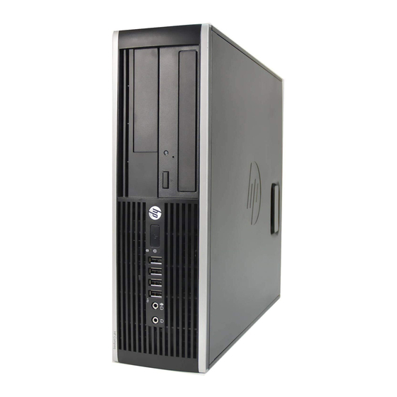
Page 18: Small Form Factor
Small Form Factor Standard Configuration Features The HP Compaq Small Form Factor features may vary depending on the model. For a complete listing of the hardware and software installed in the computer, run the diagnostic utility (included on some computer models only). Instructions for using the utility are provided in the Troubleshooting Guide. -
Page 19: Front Panel Components
Front Panel Components Drive configuration may vary by model. Figure 1-5 Front Panel Components Table 1-4 Front Panel Components 5.25-inch Optical Drive USB (Universal Serial Bus) Ports Optical Drive Activity Light Microphone/Headphone Connector Optical Drive Eject Button 3.5-inch Media Card Reader (optional) Dual-State Power Button Hard Drive Activity Light Power On Light... -
Page 20: Media Card Reader Components
Media Card Reader Components The media card reader is an optional device available on some models only. Refer to the following illustration and table to identify the media card reader components. Figure 1-6 Media Card Reader Components Table 1-5 Media Card Reader Components Slot Media ●... -
Page 21: Rear Panel Components
Arrangement and number of connectors may vary by model. An optional second serial port and an optional parallel port are available from HP. When a device is plugged into the blue Line-In Audio Connector, a dialog box will pop up asking if you want to use the connector for a line-in device or a microphone. -
Page 22: Serial Number Location
Serial Number Location Each computer has a unique serial number and product ID number in the location shown below. Keep these numbers available for use when contacting customer service for assistance. Figure 1-8 Serial Number and Product ID Location Chapter 1 Product Features... -
Page 23: Installing And Customizing The Software
If the computer was shipped with Windows Vista or Windows 7 loaded, you will be prompted to register the computer with HP Total Care before installing the operating system. You will see a brief movie followed by an online registration form. Fill out the form, click the Begin button, and follow the instructions on the screen. -
Page 24: Installing The Operating System
Obtain the latest support software, including support software for the operating system from http://www.hp.com/support. Select your country and language, select Download drivers and software (and firmware), enter the model number of the computer, and press Enter. Chapter 2 Installing and Customizing the Software... -
Page 25: Accessing Disk Image (Iso) Files
Corel WinDVD SD and BD – installation software for WinDVD – used to play DVD movies ● HP Insight Diagnostics OR Vision Diagnostics – software to perform diagnostic activities on your Protecting the Software To protect the software from loss or damage, keep a backup copy of all system software, applications, and related files stored on the hard drive. -
Page 26: Computer Setup (F10) Utility
Computer Setup (F10) Utility Computer Setup (F10) Utilities Use Computer Setup (F10) Utility to do the following: ● Change system default settings. ● Set the system date and time. ● Set, view, change, or verify the system configuration, including settings for processor, graphics, memory, audio, storage, communications, and input devices. -
Page 27: Using Computer Setup (F10) Utilities
● Replicate the system setup by saving system configuration information on USB flash media device or other storage media emulating a diskette and restoring it on one or more computers. ● Execute self-tests on a specified ATA hard drive (when supported by drive). ●... -
Page 28: Computer Setup-File
Computer Setup—File NOTE: Support for specific Computer Setup options may vary depending on the hardware configuration. Table 3-2 Computer Setup—File Option Description System Information Lists: ● Product name ● SKU number (some models) ● Processor type/speed/stepping ● Cache size (L1/L2/L3) ●... -
Page 29: Computer Setup-Storage
Computer Setup—Storage NOTE: Support for specific Computer Setup options may vary depending on the hardware configuration. Table 3-3 Computer Setup—Storage Option Description Device Configuration Lists all installed BIOS-controlled storage devices. When a device is selected, detailed information and options are displayed. The following options may be presented. - Page 30 (blue screen). RAID volumes may become corrupted if they are booted to after disabling RAID. For more information on RAID, go to http://www.hp.com/support. Select your country and language, select See support and troubleshooting information, enter the model number of the computer, and press Enter.
- Page 31 Table 3-3 Computer Setup—Storage (continued) Option Description DPS Self-Test Allows you to execute self-tests on ATA hard drives capable of performing the Drive Protection System (DPS) self-tests. NOTE: This selection will only appear when at least one drive capable of performing the DPS self-tests is attached to the system.
-
Page 32: Computer Setup-Security
Computer Setup—Security NOTE: Support for specific Computer Setup options may vary depending on the hardware configuration. Table 3-4 Computer Setup—Security Option Description Setup Password Allows you to set and enable setup (administrator) password. NOTE: If the setup password is set, it is required to change Computer Setup options, flash the ROM, and make changes to certain plug and play settings under Windows. - Page 33 Table 3-4 Computer Setup—Security (continued) Option Description Device Security Allows you to set Device Available/Device Hidden for ● Serial ports ● Parallel port ● System audio ● Network controllers (some models) ● Embedded security device (some models) ● SATA0 ● SATA1 ●...
- Page 34 Table 3-4 Computer Setup—Security (continued) Option Description System Security (some Data Execution Prevention (some models) (enable/disable) Helps prevent operating system security models: these options breaches. are hardware Virtualization Technology (some models) (enable/disable) Controls the virtualization features of the dependent) processor. Changing this setting requires turning the computer off and then back on. Embedded Security Device Support (some models) (enable/disable) Permits activation and deactivation of the Embedded Security Device.
-
Page 35: Computer Setup-Power
Computer Setup—Power NOTE: Support for specific Computer Setup options may vary depending on the hardware configuration. Table 3-5 Computer Setup—Power Option Description OS Power ● Idle Power Savings—Extended/Normal. Allows certain operating systems to decrease the Management processors power consumption when the processor is idle. ●... -
Page 36: Computer Setup-Advanced
Computer Setup—Advanced NOTE: Support for specific Computer Setup options may vary depending on the hardware configuration. Table 3-6 Computer Setup—Advanced (for advanced users) Option Description Power-On Options Allows you to set: ● POST mode (QuickBoot, Clear Memory, FullBoot, or FullBoot Every x Days). ◦... - Page 37 Table 3-6 Computer Setup—Advanced (for advanced users) (continued) Option Description ◦ Clear Memory = No memory count on cold boot. Clears memory on all boots. ◦ FullBoot Every x Days = Memory count on 1st cold boot on or after the xth day. No more memory counts until 1st cold boot on or after x days.
- Page 38 Table 3-6 Computer Setup—Advanced (for advanced users) (continued) Option Description PCI Devices ● Lists currently installed PCI devices and their IRQ settings. ● Allows you to reconfigure IRQ settings for these devices or to disable them entirely. These settings have no effect under an ACPI-based operating system. PCI VGA Configuration Displayed only if there are one or more PCI graphics controllers in the system and the integrated video is enabled.
-
Page 39: Recovering The Configuration Settings
Table 3-6 Computer Setup—Advanced (for advanced users) (continued) Option Description from being used by the operating system and reduces the power used by the computer in S5. ● Processor cache (enable/disable). ● Multi-Processor (enable/disable). This option may be used to disable multi-processor support under the OS. -
Page 40: Computer Diagnostic Features
Accessing HP Vision Diagnostics To access HP Vision Diagnostics, you must burn the utility onto a CD or copy it onto a USB flash drive then boot to the CD or USB flash drive. It can also be downloaded from http://www.hp.com... -
Page 41: Survey Tab
HP Vision Diagnostics. If running HP Vision Diagnostics, select the appropriate language and click Continue. In the End User License Agreement page, select Agree if you agree with the terms. The HP Vision Diagnostics utility launches with the Survey tab displayed. -
Page 42: Status Tab
Memory can not be tested from within the HP Vision Diagnostics application. To test the memory in your computer, you must exit HP Vision Diagnostics, boot to either the CD or USB flash drive and select HP Memory Test from the boot menu. -
Page 43: History Tab
The Help tab contains a Vision Help section, and a Test Components section. This tab includes search and index features. You may also review the HP End User License Agreement (EULA), as well as the HP Vision Diagnostic application version information on this tab. -
Page 44: Saving And Printing Information In Hp Vision Diagnostics
The Memory test tab section provides information on the HP Memory Test application that may be launched from the boot menu. The HP Support section provides information on obtaining technical support from HP. Saving and Printing Information in HP Vision Diagnostics You can save the information displayed in the HP Vision Diagnostics Survey, History and Errors tabs to a diskette or a USB flash drive. -
Page 45: Desktop Management
1995 with the introduction of the industry’s first fully manageable desktop personal computers. HP is a patent holder of manageability technology. Since then, HP has led an industry-wide effort to develop the standards and infrastructure required to effectively deploy, configure, and manage desktops, workstations, and notebook PCs. -
Page 46: Hp Client Automation Agent
Software Manager, HP Instant Support Professional Edition, and HP Client Management Interface to enable a centralized model for the managing, tracking, and monitoring of all supported HP hardware. HP Client Manager 7.0 features a brand new Portal Page which serves as a one-stop-shop where the administrator can accomplish the following management tasks: ●... -
Page 47: Remote System Installation
F12 = Network Service Boot message appears in the lower-right corner of the HP logo screen when the computer is booting up. Follow the instructions on the screen to continue the process. The default boot order is a BIOS configuration setting that can be changed to always attempt to PXE boot. -
Page 48: Hp Client Management Interface
HP SoftPaq Download Manager is a free, easy-to-use interface for locating and downloading software updates for the HP client PC models in your environment. By specifying your models, operating system, and language, you can quickly locate, sort, and select the softpaqs you need. To download HP SoftPaq Download Manager, visit http://www.hp.com/go/sdm. -
Page 49: Hp Protecttools Security Manager
Module (TPM) embedded security chip is installed. HP ProtectTools software modules may be preinstalled, preloaded, or available for download from the HP Web site. For select HP Pro Desktops, HP ProtectTools is available as an after market option. Visit http://www.hp.com/products/security for more information. -
Page 50: Hp Client Automation Starter And Standard Editions
HP Client Automation is a hardware and software management solution for Windows Vista, Windows XP and HP Thin Client environments that is easy to use and quick to deploy, while providing a strong foundation for future requirements. It is offered in two editions: ●... -
Page 51: Altiris Client Management Suite
● Diagnostics—remotely run & view reports on HP desktop, notebook, and workstation models ● System Health Scan—check for known hardware issues in your installed base of HP client systems ● Active Chat—connect to HP customer support to resolve issues ●... -
Page 52: Remote Management Technology
Configuring the Intel Management Engine NOTE: For an overview of Intel vPro technology, visit http://www.intel.com/vpro. For HP-specific information on Intel vPro technology, see the white papers at http://www.hp.com/ support. Select your country and language, select See support and troubleshooting information, enter the model number of the computer, and press Enter. - Page 53 Available management technologies include the following: ● AMT (includes DASH 1.0) ● ● DASH 1.1 (using a Broadcom NIC) ASF and AMT may not be configured at the same time, but both are supported. To configure Intel vPro systems for AMT or ASF: Turn on or restart the computer.
-
Page 54: Verdiem Surveyor
An HP SoftPaq containing the Surveyor agent may be downloaded from the HP Support site and installed on supported commercial desktop models. Surveyor licenses for managing PCs may be purchased through your HP representative. -
Page 55: Retired Solutions
Computer Setup (F10) Utility, you can protect the ROM from being unintentionally updated or overwritten. This is important to ensure the operating integrity of the computer. Should you need or want to upgrade the BIOS, you may download the latest BIOS images from the HP driver and support page, http://www.hp.com/support/files. -
Page 56: Boot Block Emergency Recovery Mode
Boot Block Emergency Recovery Mode Boot Block Emergency Recovery Mode permits system recovery in the unlikely event of a ROM flash failure. For example, if a power failure were to occur during a BIOS upgrade, the ROM flash would be incomplete. -
Page 57: Replicating The Setup
NOTE: System Software Manager (SSM) can be used to replicate computer setup information from within the Windows operating system. For more information see the SSM User’s Guide at http://www.hp.com/go/ssm. Copying to Single Computer CAUTION: A setup configuration is model-specific. File system corruption may result if source and target computers are not the same model. -
Page 58: Creating A Bootable Device
Creating a Bootable Device Supported USB Flash Media Device Supported devices have a preinstalled image to simplify the process of making them bootable. All HP or Compaq and most other USB flash media devices have this preinstalled image. If the USB flash media... - Page 59 To create a bootable USB flash media device, you must have: ● a supported USB flash media device ● a bootable DOS diskette with the FDISK and SYS programs (If SYS is not available, FORMAT may be used, but all existing files on the USB flash media device will be lost.) ●...
-
Page 60: Unsupported Usb Flash Media Device
Copy any files you saved in step 9 back to your USB flash media device. Remove the diskette and reboot the computer. The computer will boot to the USB flash media device as drive C. NOTE: The default boot order varies from computer to computer, and it can be changed in the Computer Setup (F10) Utility. -
Page 61: Dual-State Power Button
If the system did not automatically restart when exiting FDISK, press Ctrl+Alt+Del to reboot to the DOS diskette. At the A:\ prompt, type FORMAT C: /S and press Enter. Format will format the USB flash media device, add the system files, and ask for a Volume Label. Press Enter for no label or enter one if desired. -
Page 62: Hp Web Site Support
HP has made the task of locating, accessing, evaluating, and installing the latest support software easier. You can download the software from http://www.hp.com/support. - Page 63 Computer Setup Utilities. ● Remotely, using HP Client Manager from Symantec, HP Client Automation, or System Software Manager. This software enables the secure, consistent deployment and control of security settings.
- Page 64 Allows you to remotely monitor, manage, and track your computer. ProtectTools Once activated, LoJack Pro for HP ProtectTools is configured from the Absolute Software Customer Center. From the Customer Center, the administrator can configure LoJack for HP ProtectTools to monitor or manage the computer. If the system is misplaced or stolen, the Customer Center can assist local authorities to locate and recover the computer.
- Page 65 Table 5-1 Security Features Overview (continued) Setup Security Level Provides a method to allow end-users limited access to change specified setup options, without having to know the Setup Password. This feature allows the administrator the flexibility to protect changes to essential setup options, while allowing the user to view system settings and configure nonessential options.
-
Page 66: Password Security
Client Management Interface Technical Whitepaper at http://www.hp.com/go/hpcmi. Establishing a Setup Password Using Computer Setup If the system is equipped with an embedded security device, refer to the HP ProtectTools Security Manager Guide at http://www.hp.com. Establishing a setup password through Computer Setup prevents reconfiguration of the computer (use of the Computer Setup (F10) utility) until the password is entered. -
Page 67: Entering A Power-On Password
Entering a Setup Password If the system is equipped with an embedded security device, refer to the HP ProtectTools Security Manager Guide at http://www.hp.com. -
Page 68: Deleting A Power-On Or Setup Password
Security options in Computer Setup. Deleting a Power-On or Setup Password If the system is equipped with an embedded security device, refer to the HP ProtectTools Security Manager Guide at http://www.hp.com. Turn on or restart the computer. If you are in Windows, click Start > Shut Down > Restart the Computer. -
Page 69: Clearing Passwords
If you forget the password, you cannot access the computer. Refer to the Troubleshooting Guide for instructions on clearing passwords. If the system is equipped with an embedded security device, refer to the HP ProtectTools Security Manager Guide at http://www.hp.com. -
Page 70: Drivelock Applications
For users with less stringent security requirements, HP does not recommend enabling DriveLock. Users in this category include personal users or users who do not maintain sensitive data on their hard drives as a common practice. -
Page 71: Smart Cover Lock
Before exiting, click File > Save Changes and Exit. Smart Cover Lock The Smart Cover Lock is a software-controllable cover lock featured on some HP computers. This lock prevents unauthorized access to the internal components. Computers ship with the Smart Cover Lock in the unlocked position. -
Page 72: Cable Lock Provision
If the computer is connected to a network managed by HP Client Manager, the computer sends a fault notice to the network management application. With HP Client Manager Software, you can also remotely schedule diagnostics to automatically run on all managed PCs and create a summary report of failed tests. -
Page 73: Thermal Sensor
Thermal Sensor The thermal sensor is a hardware and software feature that tracks the internal temperature of the computer. This feature displays a caution message when the normal range is exceeded, which gives you time to take action before internal components are damaged or data is lost. CAUTION: A high temperature condition can result in damage to the system or data loss. -
Page 74: Serial Ata Drive Guidelines And Features
Serial ATA Drive Guidelines and Features NOTE: Serial ATA = SATA HP only supports the use of SATA hard drives on these computers. SATA Hard Drives Serial ATA Hard Drive Characteristics Number of pins/conductors in data cable Number of pins in power cable Maximum data cable length 39.37 in (100 cm) -
Page 75: Sata Hard Drive Cables
SATA Hard Drive Cables SATA Data Cable Always use an HP approved SATA 3.0 Gb/s cable as it is fully backwards compatible with the SATA 1.5 Gb/s drives. Current HP desktop products ship with SATA 3.0 Gb/s hard drives. SATA data cables are susceptible to damage if overflexed. Never crease a SATA data cable and never bend it tighter than a 30 mm (1.18 in) radius. -
Page 76: Ata Smart Drives
ATA SMART Drives The Self Monitoring Analysis and Recording Technology (SMART) ATA drives for the HP Personal Computers have built-in drive failure prediction that warns the user or network administrator of an impending failure or crash of the hard drive. The SMART drive tracks fault prediction and failure indication parameters such as reallocated sector count, spin retry count, and calibration retry count. -
Page 77: Identifying The Chassis, Routine Care, And Disassembly Preparation
You must disconnect the power cord from the power source before opening the computer to prevent system board or component damage. Chassis Designations The following subsections illustrate the HP Compaq 6000 Pro Microtower Business PC chassis designs. Small Form Factor (SFF) Chassis Designations... -
Page 78: Microtower (Mt)
Microtower (MT) Electrostatic Discharge Information A sudden discharge of static electricity from your finger or other conductor can destroy static-sensitive devices or microcircuitry. Often the spark is neither felt nor heard, but damage occurs. An electronic device exposed to electrostatic discharge (ESD) may not appear to be affected at all and can work perfectly throughout a normal cycle. -
Page 79: Preventing Electrostatic Damage To Equipment
Removing DIPs* from vinyl tray 2,000 V 4,000 V 11,500 V Removing DIPs* from Styrofoam 3,500 V 5,000 V 14,500 V Removing bubble pack from PCB 7,000 V 20,000 V 26,500 V Packing PCBs in foam-lined box 5,000 V 11,000 V 21,000 V *These are then multi-packaged inside plastic tubes, trays, or Styrofoam. -
Page 80: Grounding The Work Area
Grounding the Work Area To prevent static damage at the work area, use the following precautions: ● Cover the work surface with approved static-dissipative material. Provide a wrist strap connected to the work surface and properly grounded tools and equipment. ●... -
Page 81: Operating Guidelines
Operating Guidelines To prevent overheating and to help prolong the life of the computer: ● Keep the computer away from excessive moisture, direct sunlight, and extremes of heat and cold. ● Operate the computer on a sturdy, level surface. Leave a 10.2-cm (4-inch) clearance on all vented sides of the computer and above the monitor to permit the required airflow. -
Page 82: Cleaning The Keyboard
To clean the computer case, follow the procedures described below: ● To remove light stains or dirt, use plain water with a clean, lint-free cloth or swab. ● For stronger stains, use a mild dishwashing liquid diluted with water. Rinse well by wiping it with a cloth or swab dampened with clear water. -
Page 83: Cleaning The Mouse
If an incorrect screw is used during the reassembly process, it can damage the unit. HP strongly recommends that all screws removed during disassembly be kept with the part that was removed, then returned to their proper locations. -
Page 84: Cables And Connectors
Batteries, battery packs, and accumulators should not be disposed of together with the general household waste. In order to forward them to recycling or proper disposal, please use the public collection system or return them to HP, their authorized partners, or their agents. Chapter 7 Identifying the Chassis, Routine Care, and Disassembly Preparation... -
Page 85: Removal And Replacement Procedures Microtower (Mt) Chassis
Removal and Replacement Procedures Microtower (MT) Chassis Adherence to the procedures and precautions described in this chapter is essential for proper service. After completing all necessary removal and replacement procedures, run the Diagnostics utility to verify that all components operate properly. NOTE: Not all features listed in this guide are available on all computers. -
Page 86: Preparation For Disassembly
Preparation for Disassembly Identifying the Chassis, Routine Care, and Disassembly Preparation on page 65 for initial safety procedures. Remove/disengage any security devices that prohibit opening the computer (External Security Devices on page 116). Close any open software applications. Exit the operating system. Remove any diskette, compact disc, or media card from the computer. -
Page 87: Access Panel
Access Panel Prepare the computer for disassembly (Preparation for Disassembly on page 74). CAUTION: Before removing the computer access panel, ensure that the computer is turned off and that the power cord is disconnected from the electrical outlet. Loosen the two captive thumbscrews (1) that secure the access panel to the computer chassis. Use the handle located between the thumbscrews to lift the access panel off the unit (2). -
Page 88: Front Bezel
Front Bezel Prepare the computer for disassembly (Preparation for Disassembly on page 74). Remove the computer access panel. Lift up the three tabs on the side of the bezel (1), then rotate the bezel off the chassis (2). Figure 8-3 Removing the Front Bezel To reinstall the front bezel, reverse the removal procedure. -
Page 89: Removing Bezel Blanks
Removing Bezel Blanks On some models, there are bezel blanks covering the 3.5-inch and 5.25-inch external drive bays that need to be removed before installing a drive. To remove a bezel blank: Remove the access panel and front bezel. To remove a bezel blank, push the two retaining tabs that hold the bezel blank in place towards the outer right edge of the bezel (1) and slide the bezel blank back and to the right to remove it (2). -
Page 90: Cable Management
Cable Management Always follow good cable management practices when working inside the computer. ● Keep cables away from major heat sources like the heat sink. ● Do not jam cables on top of expansion cards or memory modules. Printed circuit cards like these are not designed to take excessive pressure on them. -
Page 91: Cable Connections
Cable Connections System board connectors are color-coded to make it easier to find the proper connection. Connector Name Connector Color Description PWR, P1 White Power supply, 6-pin PWRCPU, P3 White Power supply, 4-pin PS STAT White Power supply, 6-pin SATS PWR 1 Black Optical drive power connector, 4-pin SATS PWR 2... -
Page 92: Memory
Memory The computer comes with double data rate 3 synchronous dynamic random access memory (DDR3- SDRAM) dual inline memory modules (DIMMs). The memory sockets on the system board can be populated with up to four industry-standard DIMMs. These memory sockets are populated with at least one preinstalled DIMM. To achieve the maximum memory support, you can populate the system board with up to 16-GB of memory configured in a high- performing dual channel mode. - Page 93 Figure 8-5 DIMM Socket Locations Table 8-1 DIMM Socket Locations Item Description Socket Color XMM1 socket, Channel A (populate fourth) White XMM2 socket, Channel B (populate third) White XMM3 socket, Channel A (populate second) Black XMM4 socket, Channel B (populate first) Black NOTE: A DIMM must occupy the black XMM4 socket.
- Page 94 Open both latches of the memory module socket (1), and insert the memory module into the socket (2). Figure 8-6 Installing a DIMM NOTE: A memory module can be installed in only one way. Match the notch on the module with the tab on the memory socket.
-
Page 95: Expansion Cards
Expansion Cards The computer has one PCI expansion slot, two PCI Express x1 expansion slots, and one PCI Express x16 expansion slot. Figure 8-7 Expansion Slot Locations Table 8-2 Expansion Slot Locations Item Description PCI expansion slot PCI Express x16 expansion slot PCI Express x1 expansion slot PCI Express x1 expansion slot NOTE:... - Page 96 Release the slot cover retention latch that secures the PCI slot covers by lifting the green tab on the latch and rotating the latch to the open position. Figure 8-8 Opening the Expansion Slot Retainer Before installing an expansion card, remove the expansion slot cover or the existing expansion card.
- Page 97 If you are removing a standard PCI card or PCI Express x1 card, hold the card at each end, and carefully rock it back and forth until the connectors pull free from the socket. Pull the expansion card straight up from the socket then away from the inside of the chassis to release it from the chassis frame.
- Page 98 If you are not installing a new expansion card, install an expansion slot cover to close the open slot. CAUTION: After removing an expansion card, you must replace it with a new card or expansion slot cover for proper cooling of internal components during operation. To install a new expansion card, hold the card just above the expansion socket on the system board then move the card toward the rear of the chassis so that the bracket on the card is aligned with the open slot on the rear of the chassis.
-
Page 99: Drive Positions
Connect external cables to the installed card, if needed. Connect internal cables to the system board, if needed. Reconfigure the computer, if necessary. Refer to the Computer Setup (F10) Utility Guide for instructions on using Computer Setup. Drive Positions Figure 8-14 Drive Positions Two 5.25-inch external drive bays for optional drives (optical drives shown) One 3.5-inch external drive bay for optional drive (media card reader shown) -
Page 100: Installing And Removing Drives
You must install guide screws to ensure the drive will line up correctly in the drive cage and lock in place. HP has provided extra guide screws for the external drive bays (four 6-32 isolation mounting guide screws and eight M3 metric guide screws), installed on the side of the drive bays. - Page 101 CAUTION: To prevent loss of work and damage to the computer or drive: If you are inserting or removing a drive, shut down the operating system properly, turn off the computer, and unplug the power cord. Do not remove a drive while the computer is on or in standby mode. Before handling a drive, ensure that you are discharged of static electricity.
-
Page 102: System Board Drive Connections
System Board Drive Connections Refer to the following illustration and table to identify the system board drive connectors. Figure 8-16 System Board Drive Connections Table 8-3 System Board Drive Connections System Board Connector System Board Label Color SATA3 SATA3 orange SATA2 SATA2 light blue... -
Page 103: Removing An External 5.25-Inch Or 3.5-Inch Drive
Removing an External 5.25-inch or 3.5-inch Drive CAUTION: All removable media should be taken out of a drive before removing the drive from the computer. Prepare the computer for disassembly (Preparation for Disassembly on page 74). Remove the access panel (Access Panel on page 75). - Page 104 If you are removing a media card reader, disconnect the USB cable from the system board. If the media card reader has a 1394 port, disconnect the 1394 cable from the PCI card. Figure 8-18 Disconnecting the Media Card Reader USB Cable Figure 8-19 Disconnecting the Media Card Reader 1394 Cable Chapter 8 Removal and Replacement Procedures Microtower (MT) Chassis...
- Page 105 A latch drive bracket with release tabs secures the drives in the drive bay. Lift the release tab on the latch drive bracket (1) for the drive you want to remove, then slide the drive from its drive bay (2). Figure 8-20 Removing the External Drives Remove the four guide screws (two on each side) from the old drive.
-
Page 106: Installing An External 5.25-Inch Or 3.5-Inch Drive
Install four M3 metric guide screws in the lower holes on each side of the drive. HP has provided eight extra M3 metric guide screws on the front of the chassis, under the front bezel. The M3 metric guide screws are black. - Page 107 Slide the drive into the drive bay, making sure to align the guide screws with the guide slots, until the drive snaps into place. Figure 8-22 Sliding the External Drives into the Drive Cage Connect the power and data cables to the drive as indicated in the following illustrations. If you are installing an optical drive, connect the power cable (1) and data cable (2) to the back of the drive.
- Page 108 If you are installing a media card reader, connect the USB cable to the system board. If the media card reader has a 1394 port, connect the 1394 cable to the PCI card. Figure 8-24 Connecting the Media Card Reader USB Cable Figure 8-25 Connecting the Media Card Reader 1394 Cable If installing a new drive, connect the opposite end of the data cable to the appropriate system board...
-
Page 109: Removing An Internal 3.5-Inch Hard Drive
Removing an Internal 3.5-inch Hard Drive NOTE: Before you remove the old hard drive, be sure to back up the data from the old hard drive so that you can transfer the data to the new hard drive. Prepare the computer for disassembly (Preparation for Disassembly on page 74). -
Page 110: Installing An Internal 3.5-Inch Hard Drive
NOTE: The hard drive uses 6-32 isolation mounting guide screws. Four extra guide screws are installed on the exterior of the hard drive bays. The HP-supplied isolation mounting guide screws are silver and blue. Refer to Installing and Removing Driveson page 88 for an illustration of the extra 6-32 isolation mounting guide screws location. -
Page 111: Removing And Replacing A Removable 3.5-Inch Sata Hard Drive
Connect the power cable (1) and data cable (2) to the back of the hard drive. Figure 8-30 Connecting the Hard Drive Cables CAUTION: Never crease or bend a SATA data cable tighter than a 30 mm (1.18 in) radius. A sharp bend can break the internal wires. - Page 112 Remove the screw from the rear of the carrier (1) and slide the top cover off the carrier (2). Figure 8-31 Removing the Carrier Cover Remove the adhesive strip that secures the thermal sensor to the top of the hard drive (1) and move the thermal sensor away from the carrier (2).
- Page 113 Remove the four screws from the bottom of the hard drive carrier. Figure 8-33 Removing the Security Screws Slide the hard drive back to disconnect it from the carrier then lift it up and out of the carrier. Figure 8-34 Removing the Hard Drive Installing and Removing Drives 101...
- Page 114 Place the new hard drive in the carrier then slide the hard drive back so that it seats in the SATA connector on the carrier's circuit board. Be sure the connector on the hard drive is pressed all the way into the connector on the carrier's circuit board. Figure 8-35 Replacing the Hard Drive Replace the four screws in the bottom of the carrier to hold the drive securely in place.
- Page 115 Place the thermal sensor on top of the hard drive in a position that does not cover the label (1) and attach the thermal sensor to the top of the hard drive with the adhesive strip (2). Figure 8-37 Replacing the Thermal Sensor Slide the cover on the carrier (1) and replace the screw on the rear of the carrier to secure the cover in place (2).
-
Page 116: Fan/Baffle Assembly
Fan/Baffle Assembly Prepare the computer for disassembly (Preparation for Disassembly on page 74). Remove the access panel (Access Panel on page 75). Unplug the fan cable from the system board (CHFAN1, P9). Press the lever that secures the assembly to the chassis (1), pivot the assembly forward toward the front of the computer (2), and then lift the assembly straight up and out of the computer (3). -
Page 117: Front I/O Assembly
Front I/O Assembly Prepare the computer for disassembly (Preparation for Disassembly on page 74). Remove the computer access panel (Access Panel on page 75). Remove the front bezel (Front Bezel on page 76). Remove the cables from the clip on top of the baffle. Disconnect the three front I/O cables (yellow, green, and blue) from the system board connectors (FRNT_USB1, FRNT_USB2, and FRNT_AUD). -
Page 118: Power Switch/Led Assembly
Power Switch/LED Assembly Prepare the computer for disassembly (Preparation for Disassembly on page 74). Remove the access panel (Access Panel on page 75). Remove the front bezel (Front Bezel on page 76). Disconnect the cable from the system board (P5, PB/LED). With the computer on its side, press on the bottom of the assembly (1) and rotate upward (2) to disengage it from the chassis. -
Page 119: Heat Sink
Heat sink WARNING! To reduce risk of personal injury from hot surfaces, allow the internal system components to cool before touching. Prepare the computer for disassembly (Preparation for Disassembly on page 74). Remove the computer access panel (Access Panel on page 75). -
Page 120: Processor
Processor Prepare the computer for disassembly (Preparation for Disassembly on page 74). Remove the access panel (Access Panel on page 75). Remove the heat sink (Heat sink on page 107). Rotate the locking lever to its full open position (1). Carefully lift the processor from the socket (2). -
Page 121: Speaker
After installing a new processor onto the system board, always update the system ROM to ensure that the latest version of the BIOS is being used on the computer. The latest system BIOS can be found on the Web at: http://h18000.www1.hp.com/support/files. Speaker... -
Page 122: Rear Chassis Fan
Rear Chassis Fan Prepare the computer for disassembly (Preparation for Disassembly on page 74). Remove the access panel (Access Panel on page 75). Disconnect the fan control cable from the system board (CHFAN2). Remove the four silver Phillips screws that secure the fan to the chassis. Lift the fan out of the chassis. -
Page 123: Power Supply
Power Supply Prepare the computer for disassembly (Preparation for Disassembly on page 74). Remove the access panel (Access Panel on page 75). Disconnect all power cables from the drives and from the system board. Remove the four silver T15 screws that connect the power supply to the chassis. Press the tab on the base pan in front of the power supply that holds it in place. -
Page 124: System Board
System Board Prepare the computer for disassembly (Preparation for Disassembly on page 74). Remove the access panel (Access Panel on page 75). Remove all expansion boards (Expansion Cards on page 83). Disconnect all cables connected to the system board, noting their location for reinstallation. Remove the heat sink (Heat sink on page 107). -
Page 125: Battery
The lifetime of the lithium battery can be extended by plugging the computer into a live AC wall socket. The lithium battery is only used when the computer is NOT connected to AC power. HP encourages customers to recycle used electronic hardware, HP original print cartridges, and rechargeable batteries. For more information about recycling programs, go to http://www.hp.com/... -
Page 126: Type 1 Battery Holder
Type 1 Battery Holder Lift the battery out of its holder. Slide the replacement battery into position, positive side up. The battery holder automatically secures the battery in the proper position. Replace the computer access panel. Plug in the computer and turn on power to the computer. Reset the date and time and any special system setups using Computer Setup. -
Page 127: Type 3 Battery Holder
Plug in the computer and turn on power to the computer. Reset the date and time and any special system setups using Computer Setup. Refer to the Computer Setup (F10) Utility Guide. Type 3 Battery Holder Pull back on the clip (1) that holds the battery in place, then remove the battery (2). Insert the new battery and position the clip back in place. -
Page 128: External Security Devices
External Security Devices The following security devices are used to prevent unauthorized access to the internal components of the computer and/or secure the computer to a fixed object. Cable Lock Figure 8-39 Installing a Cable Lock Padlock Figure 8-40 Installing a Padlock 116 Chapter 8 Removal and Replacement Procedures Microtower (MT) Chassis... -
Page 129: Hp Business Pc Security Lock
HP Business PC Security Lock Fasten the security cable by looping it around a stationary object. Figure 8-41 Securing the Cable to a Fixed Object Thread the keyboard and mouse cables through the lock. Figure 8-42 Threading the Keyboard and Mouse Cables... -
Page 130: Front Bezel Security
Use the key provided to disengage the lock. Figure 8-44 Engaging the Lock Front Bezel Security The front bezel can be locked in place by installing a security screw provided by HP. To install the security screw: Prepare the computer for disassembly (Preparation for Disassembly on page 74). - Page 131 Remove the security screw from the inside of the front bezel. Figure 8-45 Retrieving the Front Bezel Security Screw Replace the front bezel. Install the screw through the interior of the front of the chassis into the front bezel. The screw hole is located toward the middle of the right edge of the chassis between the hard drive bay and speaker.
-
Page 132: Removal And Replacement Procedures Small Form Factor (Sff) Chassis
Removal and Replacement Procedures Small Form Factor (SFF) Chassis Adherence to the procedures and precautions described in this chapter is essential for proper service. After completing all necessary removal and replacement procedures, run the Diagnostics utility to verify that all components operate properly. NOTE: Not all features listed in this guide are available on all computers. -
Page 133: Access Panel
Access Panel Prepare the computer for disassembly (Preparation for Disassembly on page 120). Lift up on the access panel handle (1) then lift the access panel off the computer (2). Figure 9-1 Removing the Access Panel To install the access panel, reverse the removal procedure. Access Panel 121... -
Page 134: Front Bezel
Front Bezel Prepare the computer for disassembly (Preparation for Disassembly on page 120). Remove the access panel (Access Panel on page 121). Lift up the three tabs on the side of the bezel (1), then rotate the bezel off the chassis (2). Figure 9-2 Removing the Front Bezel To install the front bezel, reverse the removal procedure. -
Page 135: Bezel Blanks
Bezel Blanks On some models, there are bezel blanks covering the 3.5-inch and 5.25-inch external drive bays that need to be removed before installing a drive. To remove a bezel blank: Remove the access panel (Access Panel on page 121). Remove the front bezel (Front Bezel on page 122).. -
Page 136: Installing Additional Memory
Installing Additional Memory The computer comes with double data rate 3 synchronous dynamic random access memory (DDR3- SDRAM) dual inline memory modules (DIMMs). DIMMs The memory sockets on the system board can be populated with up to four industry-standard DIMMs. These memory sockets are populated with at least one preinstalled DIMM. -
Page 137: Populating Dimm Sockets
Populating DIMM Sockets There are four DIMM sockets on the system board, with two sockets per channel. The sockets are labeled XMM1, XMM2, XMM3, and XMM4. Sockets XMM1 and XMM3 operate in memory channel A. Sockets XMM2 and XMM4 operate in memory channel B. Figure 9-4 DIMM Socket Locations Table 9-1... - Page 138 Prepare the computer for disassembly (Preparation for Disassembly on page 120). Remove the access panel (Access Panel on page 121). Rotate up the external drive bay housing to access the memory module sockets on the system board. Figure 9-5 Rotating the Drive Cage Up 126 Chapter 9 Removal and Replacement Procedures Small Form Factor (SFF) Chassis...
- Page 139 Open both latches of the memory module socket (1), and insert the memory module into the socket (2). Figure 9-6 Installing a DIMM NOTE: A memory module can be installed in only one way. Match the notch on the module with the tab on the memory socket.
-
Page 140: Expansion Cards
Expansion Cards The computer has one PCI expansion slot, two PCI Express x1 expansion slots, and one PCI Express x16 expansion slot. NOTE: The PCI and PCI Express slots support only low profile cards. Figure 9-7 Expansion Slot Locations Table 9-2 Expansion Slot Locations Item Description... - Page 141 Release the slot cover retention latch that secures the PCI slot covers by lifting the green tab on the latch and rotating the latch to the open position. Figure 9-8 Opening the Expansion Slot Retainer Before installing an expansion card, remove the expansion slot cover or the existing expansion card.
- Page 142 If you are removing a standard PCI card or PCI Express x1 card, hold the card at each end, and carefully rock it back and forth until the connectors pull free from the socket. Pull the expansion card straight up from the socket then away from the inside of the chassis to release it from the chassis frame.
- Page 143 Store the removed card in anti-static packaging. If you are not installing a new expansion card, install an expansion slot cover to close the open slot. CAUTION: After removing an expansion card, you must replace it with a new card or expansion slot cover for proper cooling of internal components during operation.
- Page 144 Rotate the slot cover retention latch back in place to secure the expansion card. Figure 9-13 Closing the Expansion Slot Retainer Connect external cables to the installed card, if needed. Connect internal cables to the system board, if needed. Reconfigure the computer, if necessary. Refer to the Computer Setup (F10) Utility Guide for instructions on using Computer Setup.
-
Page 145: Cable Management
Cable Management The Small Form Factor chassis is a very compact computer and proper routing of the internal cables is critical to the operation of the computer. Follow good cable management practices when working inside the computer. ● Keep cables away from major heat sources like the heat sink. ●... -
Page 146: Cable Connections
Cable Connections System board connectors are color-coded to make it easier to find the proper connection. Connector Name Connector Color Description PWR, P1 White Power supply, 6-pin PWRCPU, P3 White Power supply, 4-pin PS STAT White Power supply, 6-pin SATS PWR 1 Black Optical drive power connector, 4-pin SATS PWR 2... -
Page 147: Drive Positions
Drive Positions Figure 9-15 Drive Positions Table 9-3 Drive Positions 3.5-inch internal hard drive bay 3.5-inch external drive bay for optional drives (media card reader shown) 5.25-inch external drive bay for optional drives (optical drive shown) NOTE: The drive configuration on your computer may be different than the drive configuration shown above. -
Page 148: Installing And Removing Drives
You must install guide screws to ensure the drive will line up correctly in the drive cage and lock in place. HP has provided extra guide screws for the external drive bays (five 6-32 standard screws and four M3 metric screws), installed in the front of the chassis, under the front bezel. The 6-32 standard screws are required for a secondary hard drive. - Page 149 CAUTION: To prevent loss of work and damage to the computer or drive: If you are inserting or removing a drive, shut down the operating system properly, turn off the computer, and unplug the power cord. Do not remove a drive while the computer is on or in standby mode. Before handling a drive, ensure that you are discharged of static electricity.
-
Page 150: System Board Drive Connections
System Board Drive Connections Refer to the following illustration and table to identify the system board drive connectors. Figure 9-17 System Board Drive Connections Table 9-4 System Board Drive Connections System Board Connector System Board Label Color SATA3 SATA3 orange SATA2 SATA2 light blue... -
Page 151: Removing An External 5.25-Inch Drive
Removing an External 5.25-inch Drive CAUTION: All removable media should be taken out of a drive before removing the drive from the computer. To remove a 5.25-inch external drive: Prepare the computer for disassembly (Preparation for Disassembly on page 120). Remove the access panel (Access Panel on page 121). -
Page 152: Installing An Optical Drive Into The 5.25-Inch Drive Bay
Rotate the drive cage back down to its normal position. CAUTION: Be careful not to pinch any cables or wires when rotating the drive cage down. Figure 9-20 Rotating the Drive Cage Down Press down on the green drive retainer button located on the left side of the drive to disengage the drive from the drive cage (1). - Page 153 Install four M3 metric guide screws in the lower holes on each side of the drive. HP has provided four extra M3 metric guide screws on the front of the chassis, under the front bezel. The M3 metric guide screws are black. Refer to...
- Page 154 Rotate the drive cage to its upright position. Figure 9-24 Rotating the Drive Cage Up Connect the SATA data cable to the white system board connector labeled SATA1. Route the data cable through the cable guides. CAUTION: There are two cable guides that keep the data cable from being pinched by the drive cage when raising or lowering it.
-
Page 155: Removing An External 3.5-Inch Drive
Rotate the drive cage back down to its normal position. CAUTION: Be careful not to pinch any cables or wires when rotating the drive cage down. Figure 9-26 Rotating the Drive Cage Down Replace the access panel. The system automatically recognizes the drive and reconfigures the computer. Removing an External 3.5-inch Drive CAUTION: All removable media should be taken out of a drive before removing the drive from the... - Page 156 Disconnect the drive cables from the rear of the drive, or, if you are removing a media card reader, disconnect the USB and 1394 cables from the system board as indicated in the following illustrations. NOTE: On some models, the media card reader does not include a 1394 port or cable. Figure 9-27 Disconnecting the Media Card Reader USB Cable Figure 9-28...
-
Page 157: Installing A Drive Into The 3.5-Inch External Drive Bay
Install guide screws to ensure the drive will line up correctly in the drive cage and lock in place. HP has provided extra guide screws for the external drive bays (four 6-32 standard screws and four M3 metric screws), installed in the front of the chassis, under the front bezel. A secondary hard drive uses 6-32 standard screws. - Page 158 Position the guide screws on the drive into the J-slots in the drive bay. Then slide the drive toward the front of the computer until it locks into place. Figure 9-30 Installing a Drive into the 3.5-inch Drive Bay (Media Card Reader Shown) Connect the appropriate drive cables: If installing a second hard drive, connect the power and data cables to the rear of the drive and connect the other end of the data cable to the next available (unpopulated) SATA...
-
Page 159: Removing And Replacing The Primary 3.5-Inch Internal Sata Hard Drive
Removing and Replacing the Primary 3.5-inch Internal SATA Hard Drive NOTE: The system does not support Parallel ATA (PATA) hard drives. Before you remove the old hard drive, be sure to back up the data from the old hard drive so that you can transfer the data to the new hard drive. - Page 160 Rotate the power supply to its upright position. The hard drive is located beneath the power supply. Figure 9-32 Raising the Power Supply Disconnect the power cable (1) and data cable (2) from the back of the hard drive. Figure 9-33 Disconnecting the Hard Drive Power Cable and Data Cable 148 Chapter 9 Removal and Replacement Procedures Small Form Factor (SFF) Chassis...
- Page 161 Press down on the green release latch next to the hard drive (1). While holding the latch down, slide the drive forward until it stops, then lift the drive up and out of the bay (2). Figure 9-34 Removing the Hard Drive To install a hard drive, you must transfer the silver and blue isolation mounting guide screws from the old hard drive to the new hard drive.
- Page 162 Align the guide screws with the slots on the chassis drive cage, press the hard drive down into the bay, then slide it back until it stops and locks in place. Figure 9-36 Installing the Hard Drive Connect the power and data cables to the back of the hard drive. NOTE: When replacing the primary hard drive, be sure to route the SATA and power cables through the cable guide on the bottom of the chassis frame behind the hard drive.
-
Page 163: Removing And Replacing A Removable 3.5-Inch Sata Hard Drive
Removing and Replacing a Removable 3.5-inch SATA Hard Drive Some models are equipped with a removable SATA Hard Drive Enclosure in the 5.25-inch external drive bay. The hard drive is housed in a carrier that can be quickly and easily removed from the drive bay. To remove and replace a drive in the carrier: NOTE: Before you remove the old hard drive, be sure to back up the data from the old hard drive so... - Page 164 Remove the four screws from the bottom of the hard drive carrier. Figure 9-39 Removing the Security Screws Slide the hard drive back to disconnect it from the carrier then lift it up and out of the carrier. Figure 9-40 Removing the Hard Drive 152 Chapter 9 Removal and Replacement Procedures Small Form Factor (SFF) Chassis...
- Page 165 Place the new hard drive in the carrier then slide the hard drive back so that it seats in the SATA connector on the carrier's circuit board. Be sure the connector on the hard drive is pressed all the way into the connector on the carrier's circuit board. Figure 9-41 Replacing the Hard Drive Replace the four screws in the bottom of the carrier to hold the drive securely in place.
- Page 166 Place the thermal sensor on top of the hard drive in a position that does not cover the label (1) and attach the thermal sensor to the top of the hard drive with the adhesive strip (2). Figure 9-43 Replacing the Thermal Sensor Slide the cover on the carrier (1) and replace the screw on the rear of the carrier to secure the cover in place (2).
-
Page 167: Baffle
Baffle Prepare the computer for disassembly (Preparation for Disassembly on page 120). Remove the access panel (Access Panel on page 121). Remove the cable from the arm that extends from the side of the baffle (1). Lift the baffle straight up out of the chassis (2). Figure 9-45 Removing the baffle To install the baffle, reverse the removal procedure. -
Page 168: Front Fan Assembly
Front Fan Assembly Prepare the computer for disassembly (Preparation for Disassembly on page 120). Remove the access panel (Access Panel on page 121). Remove the front bezel (Front Bezel on page 122). Remove the baffle (Baffle on page 155). Disconnect the fan cable from the system board (CH FAN1, P9). On the front of the computer, press the left and bottom tabs to disengage the fan assembly from the chassis. -
Page 169: Front I/O/Power Switch Assembly
Front I/O/Power Switch Assembly Prepare the computer for disassembly (Preparation for Disassembly on page 120). Remove the access panel (Access Panel on page 121). Remove the front bezel (Front Bezel on page 122). Remove the front fan assembly (Front Fan Assembly on page 156). - Page 170 While holding the body of the assembly, pull the assembly away from the front of the computer while guiding the cables through the hole in the drive cage (3). Figure 9-49 Guiding the wires through the drive cage Remove the assembly from the chassis. To reinstall the front I/O/power supply assembly, reverse the removal procedure.
-
Page 171: Speaker
Speaker Prepare the computer for disassembly (Preparation for Disassembly on page 120). Remove the access panel (Access Panel on page 121). Remove the front bezel (Front Bezel on page 122). Rotate the drive cage to its upright position. Disconnect the speaker wire from the system board (SPRK, P5). Remove the two screws that secure the speaker to the chassis. -
Page 172: Heat Sink
Heat sink Prepare the computer for disassembly (Preparation for Disassembly on page 120). Remove the access panel (Access Panel on page 121). Remove the baffle (Baffle on page 155). Remove the front fan assembly (Front Fan Assembly on page 156). Loosen the four captive screws that secure the heat sink to the system board tray. -
Page 173: Processor
Processor Prepare the computer for disassembly (Preparation for Disassembly on page 120). Remove the access panel (Access Panel on page 121). Remove the fan shroud (Baffle on page 155). Remove the heat sink (Heat sink on page 160). Rotate the locking lever to its full open position (1). Carefully lift the processor from the socket (2). -
Page 174: Power Supply
After installing a new processor onto the system board, always update the system ROM to ensure that the latest version of the BIOS is being used on the computer. The latest system BIOS can be found on the Web at: http://h18000.www1.hp.com/support/files. Power Supply... - Page 175 Rotate the power supply to its full upright position (1), pull the power supply forward (2) until the posts on the power supply move forward in the power supply bracket (3), and then lift the power supply straight up and out of the chassis. Figure 9-53 Removing the power supply To install the power supply, reverse the removal procedure.
-
Page 176: System Board
System Board Prepare the computer for disassembly (Preparation for Disassembly on page 120). Remove the access panel (Access Panel on page 121). Remove all PCI and PCI Express expansion boards (Expansion Cards on page 128). Remove the baffle from the chassis (Baffle on page 155). -
Page 177: Battery
Do not expose to temperatures higher than 140°F (60°C). Do not disassemble, crush, puncture, short external contacts, or dispose of in fire or water. Replace the battery only with the HP spare designated for this product. CAUTION: Before replacing the battery, it is important to back up the computer CMOS settings. When the battery is removed or replaced, the CMOS settings will be cleared. -
Page 178: Type 1 Battery Holder
Type 1 Battery Holder Lift the battery out of its holder. Figure 9-55 Removing the battery from a type 1 holder Slide the replacement battery into position, positive side up. The battery holder automatically secures the battery in the proper position. Replace the computer access panel. -
Page 179: Type 3 Battery Holder
Plug in the computer and turn on power to the computer. Reset the date and time, your passwords, and any special system setups, using Computer Setup. Refer to the Computer Setup (F10) Utility Guide. Type 3 Battery Holder Pull back on the clip (1) that holds the battery in place, then remove the battery (2). Insert the new battery and position the clip back in place. -
Page 180: External Security Devices
NOTE: For information on data security features, refer to the Computer Setup (F10) Utility Guide, the Desktop Management Guide, and the HP ProtectTools Security Manager Guide (some models) at http://www.hp.com. Installing a Security Lock The security locks displayed below and on the following pages can be used to secure the computer. -
Page 181: Padlock
Padlock Figure 9-59 Installing a Padlock HP Business PC Security Lock Fasten the security cable by looping it around a stationary object. Figure 9-60 Securing the Cable to a Fixed Object External Security Devices 169... - Page 182 Thread the keyboard and mouse cables through the lock. Figure 9-61 Threading the Keyboard and Mouse Cables Screw the lock to the chassis using the screw provided. Figure 9-62 Attaching the Lock to the Chassis 170 Chapter 9 Removal and Replacement Procedures Small Form Factor (SFF) Chassis...
-
Page 183: Front Bezel Security
Use the key provided to disengage the lock. Figure 9-63 Engaging the Lock Front Bezel Security The front bezel can be locked in place by installing a security screw provided by HP. To install the security screw: Prepare the computer for disassembly (Preparation for Disassembly on page 120). - Page 184 Install the security screw next to the middle front bezel release tab to secure the front bezel in place. Figure 9-65 Installing the Front Bezel Security Screw Replace the access panel. 172 Chapter 9 Removal and Replacement Procedures Small Form Factor (SFF) Chassis...
-
Page 185: Using The Small Form Factor Computer In A Tower Orientation
Figure 9-66 Changing from Desktop to Tower Orientation NOTE: To stabilize the computer in a tower orientation, HP recommends the use of the optional tower stand. Reconnect the power cord and any external devices, then turn on the computer. NOTE: Ensure at least 10.2 centimeters (4 inches) of space on all sides of the computer remains clear... -
Page 186: Appendix A Connector Pin Assignments
Connector Pin Assignments This appendix contains the pin assignments for many computer and workstation connectors. Some of these connectors may not be used on the product being serviced. Keyboard Connector and Icon Signal Data Unused Ground +5 VDC Clock Unused Mouse Connector and Icon Signal... -
Page 187: Ethernet Rj-45
Ethernet RJ-45 Connector and Icon Signal (+) Transmit Data (-) Transmit Data (+) Receive Data Unused Unused (-) Receive Data Unused Unused Serial Interface, Powered and Non-Powered Connector and Icon Signal Carrier Detect (12V if powered) Receive Data Transmit Data Data Terminal Ready Signal Ground Data Set Ready... -
Page 188: Microphone
Microphone Connector and Icon (1/8” miniphone) Signal 1 (Tip) Audio_left 1 2 3 2 (Ring) Audio_Right 3 (Shield) Ground Headphone Connector and Icon (1/8” miniphone) Signal 1 (Tip) Audio_left 1 2 3 2 (Ring) Power_Right 3 (Shield) Ground Line-in Audio Connector and Icon (1/8”... -
Page 189: Monitor
Monitor Connector and Icon Signal Signal Red Analog +5V (fused) Green Analog Ground Blue Analog Not used Not used DDC Serial Data Ground Horizontal Sync Ground Vertical Sync Ground DDC Serial Clock Ground 4-Pin Power (for CPU) Connector and Icon Signal +12V CPU -12V CPU... -
Page 190: Sata Data And Power
SATA Data and Power Drive Connector Signal Signal Signal Signal Ground Ground Ground Ground V 3.3 V 3.3 Ground Ground Ground Reserved Ground V 12 V 12 *S = Data, P = Power PCI Express x1, x4, x8, and x16 PCI Express Connector Pin A Signal Signal... -
Page 191: Pci Express
PERp9 PERn10 PERp8 PERn9 PERp13 PERN8 PERp12 PERn13 PERp11 PERn12 PERp10 PERn11 PERp14 PERn15 PERn14 PERp15 Pin B information is on the next page NOTE: x1 PCI Express uses pins 1-18 x4 PCI Express uses pins 1-32 x8 PCI Express uses pins 1-49 x16 PCI Express uses pins 1-8 PCI Express x1, x4, x8, and x16 PCI Express Connector... - Page 192 PRSNT2# PETp6 PETn7 PETp3 PETp5 PRTn6 PETn3 PETp4 PETn5 PRSNT2# PETn4 RSVD PETp7 PETp8 PETn8 PETp12 PETn13 PETp11 PETn12 PETp10 PETn11 PETp9 PETn10 PETp14 PETn9 PETp13 PETn14 PRSNT2# RSVD PETp15 PETn15 Pin B information is on the next page NOTE: x1 PCI Express uses pins 1-18 x4 PCI Express uses pins 1-32 x8 PCI Express uses pins 1-49...
-
Page 193: Dvi Connector
DVI Connector Connector and Icon Signal Signal T.M.D.S. Data2– T.M.D.S. Data3+ T.M.D.S. Data2+ +5V Power T.M.D.S. Data2/4 Shield Ground (for +5V) T.M.D.S. Data4– Hot Pug Detect T.M.D.S. Data4+ T.M.D.S. Data0– DDC Clock T.M.D.S. Data0+ DDC Data T.M.D.S. Data0/5 Shield No Connect T.M.D.S. -
Page 194: Displayport Connector
DisplayPort Connector Connector and Icon Signal Signal ML_Lane 0 (p) CONFIG1 Ground CONFIG2 ML_Lane 0 (n) AUX CH (p) ML_Lane 1 (p) Ground Ground AUX CH (n) ML_Lane 1 (n) Hot Plug ML_Lane 2 (p) Return Ground DP_PWR ML_Lane 2 (n) ML_Lane 3 (p) Ground ML_Lane 3 (n) -
Page 195: Appendix B Power Cord Set Requirements
Power Cord Set Requirements The power supplies on some computers have external power switches. The voltage select switch feature on the computer permits it to operate from any line voltage between 100-120 or 220-240 volts AC. Power supplies on those computers that do not have external power switches are equipped with internal switches that sense the incoming voltage and automatically switch to the proper voltage. -
Page 196: Country-Specific Requirements
Country-Specific Requirements Additional requirements specific to a country are shown in parentheses and explained below. Country Accrediting Agency Country Accrediting Agency Australia (1) EANSW Italy (1) Austria (1) Japan (3) METI Belgium (1) CEBC Norway (1) NEMKO Canada (2) Sweden (1) SEMKO Denmark (1) DEMKO... -
Page 197: Appendix C Post Error Messages
POST Error Messages This appendix lists the error codes, error messages, and the various indicator light and audible sequences that you may encounter during Power-On Self-Test (POST) or computer restart, the probable source of the problem, and steps you can take to resolve the error condition. POST Message Disabled suppresses most system messages during POST, such as memory count and non-error text messages. -
Page 198: Post Numeric Codes And Text Messages
POST Numeric Codes and Text Messages This section covers those POST errors that have numeric codes associated with them. The section also includes some text messages that may be encountered during POST. NOTE: The computer will beep once after a POST text message is displayed on the screen. Table C-1 Numeric Codes and Text Messages Control panel message... - Page 199 Memory configuration incorrect. Run Computer Setup or Windows utilities. Make sure the memory module(s) are installed properly. If third-party memory has been added, test using HP-only memory. Verify proper memory module type. 201-Memory Error RAM failure. Ensure memory modules are correctly installed.
- Page 200 Table C-1 Numeric Codes and Text Messages (continued) Control panel message Description Recommended action 301-Keyboard Error Keyboard failure. Reconnect keyboard with computer turned off. Check connector for bent or missing pins. Ensure that none of the keys are depressed. Replace keyboard. 303-Keyboard Controller Error I/O board keyboard controller.
- Page 201 Table C-1 Numeric Codes and Text Messages (continued) Control panel message Description Recommended action 605-Diskette Drive Type Error Mismatch in drive type. Disconnect any other diskette controller devices (tape drives). Clear CMOS. (See Appendix B, Password Security and Resetting CMOS on page 235.) 660-Display cache is detected unreliable Integrated graphics controller display cache...
- Page 202 Drive Protection System test under Storage > DPS Self-test. Apply hard drive firmware patch if applicable. (Available at http://www.hp.com/support.) Back up contents and replace hard drive. 1796-SATA Cabling Error One or more SATA devices are improperly Ensure SATA connectors are used in attached.
- Page 203 Table C-1 Numeric Codes and Text Messages (continued) Control panel message Description Recommended action 2202-PMM Deallocation Error during MEBx Memory error during POST execution of the Reboot the computer. cleanup Management Engine (ME) BIOS Extensions Unplug the power cord, re-seat the option ROM.
- Page 204 Table C-1 Numeric Codes and Text Messages (continued) Control panel message Description Recommended action Network Server Mode Active and No Keyboard failure while Network Server Mode Reconnect keyboard with computer Keyboard Attached enabled. turned off. Check connector for bent or missing pins.
-
Page 205: Interpreting Post Diagnostic Front Panel Leds And Audible Codes
Interpreting POST Diagnostic Front Panel LEDs and Audible Codes This section covers the front panel LED codes as well as the audible codes that may occur before or during POST that do not necessarily have an error code or text message associated with them. WARNING! When the computer is plugged into an AC power source, voltage is always applied to the system board. - Page 206 LEDs continue Reseat DIMMs. until problem is solved. Replace DIMMs one at a time to isolate the faulty module. Replace third-party memory with HP memory. Replace the system board. Red Power LED flashes six Pre-video graphics error. For systems with a graphics card: times, once every second, Reseat the graphics card.
- Page 207 Table C-2 Diagnostic Front Panel LEDs and Audible Codes (continued) Activity Beeps Possible Cause Recommended Action Red Power LED flashes nine System powers on but is Check that the voltage selector, located on times, once every second, unable to boot. the rear of the power supply (some models), followed by a two second is set to the appropriate voltage.
- Page 208 Table C-2 Diagnostic Front Panel LEDs and Audible Codes (continued) Activity Beeps Possible Cause Recommended Action Red Power LED flashes eleven The current processor Install a TXT capable processor. times, once every second, does not support a feature Disable TXT in the Computer Setup (F10) followed by a two second previously enabled on this utility.
-
Page 209: Appendix D Troubleshooting Without Diagnostics
If you are having problems with the computer, try the appropriate solutions below to try to isolate the exact problem before calling for technical support. ● Run the HP diagnostic tool. ● Run the hard drive self-test in Computer Setup. Refer to the Computer Setup (F10) Utility Guide for more information. -
Page 210: Helpful Hints
Helpful Hints on page 198 in this guide. To assist you in resolving problems online, HP Instant Support Professional Edition provides you with self-solve diagnostics. If you need to contact HP support, use HP Instant Support Professional Edition's online chat feature. Access HP Instant Support Professional Edition at: http://www.hp.com/go/ispe. - Page 211 ● Reconfigure the computer after installing a non-plug and play expansion board or other option. Solving Hardware Installation Problems on page 219 for instructions. ● Be sure that all the needed device drivers have been installed. For example, if you are using a printer, you need a driver for that model printer.
-
Page 212: Solving General Problems
Solving General Problems You may be able to easily resolve the general problems described in this section. If a problem persists and you are unable to resolve it yourself or if you feel uncomfortable about performing the operation, contact an authorized dealer or reseller. WARNING! When the computer is plugged into an AC power source, voltage is always applied to the system board. - Page 213 Unlock the Smart Cover Lock using Computer Setup. The Smart Cover FailSafe Key, a device for manually disabling the Smart Cover Lock, is available from HP. You will need the FailSafe Key in case of forgotten password, power loss, or computer malfunction.
- Page 214 Table D-1 Solving General Problems (continued) Poor performance is experienced. Cause Solution Too many applications running. Close unnecessary applications to free up memory. Add more memory. Some applications run in the background and can be closed by right-clicking on their corresponding icons in the task tray.
- Page 215 Table D-1 Solving General Problems (continued) System does not power on and the LEDs on the front of the computer are not flashing. Cause Solution System unable to power on. Press and hold the power button for less than 4 seconds. If the hard drive LED turns green, then: Remove the expansion cards one at a time until the 5V_aux light on the system board turns on.
-
Page 216: Solving Power Problems
Solving Power Problems Common causes and solutions for power problems are listed in the following table. Table D-2 Solving Power Problems Power supply shuts down intermittently. Cause Solution Power supply will not turn on because of internal power supply Contact an authorized service provider to replace the power fault. -
Page 217: Solving Hard Drive Problems
Solving Hard Drive Problems Table D-3 Solving Hard Drive Problems Hard drive error occurs. Cause Solution Hard disk has bad sectors or has failed. In Microsoft Windows XP, right-click Start, click Explore, and select a drive. Select File > Properties > Tools. - Page 218 Table D-3 Solving Hard Drive Problems (continued) Nonsystem disk/NTLDR missing message. Cause Solution The system is trying to start from a media device that is not Remove the media device from the drive. bootable. The system is trying to start from the hard drive but the hard Insert a bootable media device into the drive and restart drive may have been damaged.
- Page 219 The removable hard drive enclosure is beeping and the green LED is flashing. Cause Solution Fan failure alarm on the removable hard drive enclosure has Shut down the computer and contact HP for a replacement been activated. enclosure. Solving Hard Drive Problems 207...
-
Page 220: Solving Media Card Reader Problems
Solving Media Card Reader Problems Table D-4 Solving Media Card Reader Problems Media card will not work in a digital camera after formatting it in Microsoft Windows XP or Microsoft Windows Vista. Cause Solution By default, Windows XP and Windows Vista will format any Either format the media card in the digital camera or select FAT media card with a capacity greater than 32MB with the FAT32 file system to format the media card in a computer with... - Page 221 Table D-4 Solving Media Card Reader Problems (continued) After installing the media card reader and booting to Windows, the reader and the inserted cards are not recognized by the computer. Cause Solution The operating system needs time to recognize the device if the Wait a few seconds so that the operating system can recognize reader was just installed into the computer and you are turning the reader and the available ports, and then recognize...
-
Page 222: Solving Display Problems
Solving Display Problems If you encounter display problems, see the documentation that came with the monitor and to the common causes and solutions listed in the following table. Table D-5 Solving Display Problems Blank screen (no video). Cause Solution Monitor is not turned on and the monitor light is not on. Turn on the monitor and check that the monitor light is on. - Page 223 Reseat DIMMs. Power on the system. Replace DIMMs one at a time to isolate the faulty module. Replace third-party memory with HP memory. Replace the system board. Blank screen and the power LED flashes Red six times, once every second, followed by a two second pause, and the computer beeps six times.
- Page 224 Table D-5 Solving Display Problems (continued) Dim characters. Cause Solution The brightness and contrast controls are not set properly. Adjust the monitor brightness and contrast controls. Cables are not properly connected. Check that the graphics cable is securely connected to the graphics card and the monitor.
- Page 225 To download a SoftPaq that will assist you with the synchronization, go to the following Web site, select the appropriate monitor, and download either SP32347 or SP32202: http://www.hp.com/support Graphics card is not seated properly or is bad. Reseat the graphics card. Replace the graphics card.
-
Page 226: Solving Audio Problems
Table D-5 Solving Display Problems (continued) Certain typed symbols do not appear correct. Cause Solution The font you are using does not support that particular symbol. Use the Character Map to locate and select the appropriate symbol. Click Start > All Programs > Accessories > System Tools >... - Page 227 Table D-6 Solving Audio Problems (continued) Sound does not come out of the speaker or headphones. Cause Solution External speakers plugged into the wrong audio jack on a See the sound card documentation for proper speaker recently installed sound card. connection.
-
Page 228: Solving Printer Problems
Solving Printer Problems If you encounter printer problems, see the documentation that came with the printer and to the common causes and solutions listed in the following table. Table D-7 Solving Printer Problems Printer will not print. Cause Solution Printer is not turned on and online. Turn the printer on and make sure it is online. -
Page 229: Solving Keyboard And Mouse Problems
Solving Keyboard and Mouse Problems If you encounter keyboard or mouse problems, see the documentation that came with the equipment and to the common causes and solutions listed in the following table. Table D-8 Solving Keyboard Problems Keyboard commands and typing are not recognized by the computer. Cause Solution Keyboard connector is not properly connected. - Page 230 Table D-9 Solving Mouse Problems (continued) Mouse does not respond to movement or is too slow. Cause Solution Mouse may need cleaning. Remove the roller ball cover on the mouse and clean the internal components. Mouse may need repair. See the Worldwide Limited Warranty for terms and conditions. Computer is in standby mode.
-
Page 231: Solving Hardware Installation Problems
Solving Hardware Installation Problems You may need to reconfigure the computer when you add or remove hardware, such as an additional drive or expansion card. If you install a plug and play device, Windows automatically recognizes the device and configures the computer. If you install a non–plug and play device, you must reconfigure the computer after completing installation of the new hardware. - Page 232 Refer to the Hardware Reference Guide for your system for proper DIMM installation instructions. Replace third-party memory with HP memory. Replace the system board. Power LED flashes Red six times, once every second, followed by a two second pause, and the computer beeps six times.
-
Page 233: Solving Network Problems
Solving Network Problems Some common causes and solutions for network problems are listed in the following table. These guidelines do not discuss the process of debugging the network cabling. Table D-11 Solving Network Problems Wake-on-LAN feature is not functioning. Cause Solution Wake-on-LAN is not enabled. - Page 234 Table D-11 Solving Network Problems (continued) Network status link light never flashes. NOTE: The network status light is supposed to flash when there is network activity. Cause Solution No active network is detected. Check cabling and network equipment for proper connection. Network controller is not set up properly.
- Page 235 Table D-11 Solving Network Problems (continued) Network controller stopped working when an expansion board was added to the computer. Cause Solution The network controller requires drivers. Verify that the drivers were not accidentally deleted when the drivers for a new expansion board were installed. The expansion board installed is a network card (NIC) and Under the Computer Setup Advanced menu, change the conflicts with the embedded NIC.
-
Page 236: Solving Memory Problems
DIMM module. For those systems that support ECC memory, HP does not support mixing ECC and non-ECC memory. Otherwise, the computer will not boot the operating system. - Page 237 Cause Solution Memory is installed incorrectly or is bad. Reseat DIMMs. Power on the system. Replace DIMMs one at a time to isolate the faulty module. Replace third-party memory with HP memory. Replace the system board. Solving Memory Problems 225...
-
Page 238: Solving Processor Problems
Solving Processor Problems If you encounter processor problems, common causes and solutions are listed in the following table. Table D-13 Solving Processor Problems Poor performance is experienced. Cause Solution Processor is hot. Make sure the airflow to the computer is not blocked. Make sure the fans are connected and working properly (some fans only operate when needed). -
Page 239: Solving Cd-Rom And Dvd Problems
Solving CD-ROM and DVD Problems If you encounter CD-ROM or DVD problems, see the common causes and solutions listed in the following table or to the documentation that came with the optional device. Table D-14 Solving CD-ROM and DVD Problems System will not boot from CD-ROM or DVD drive. - Page 240 Table D-14 Solving CD-ROM and DVD Problems (continued) Movie will not play in the DVD drive. Cause Solution Movie may be regionalized for a different country. See the documentation that came with the DVD drive. Decoder software is not installed. Install decoder software.
-
Page 241: Solving Usb Flash Drive Problems
Solving USB Flash Drive Problems If you encounter USB flash drive problems, common causes and solutions are listed in the following table. Table D-15 Solving USB Flash Drive Problems USB flash drive is not seen as a drive letter in Windows. Cause Solution The drive letter after the last physical drive is not available. -
Page 242: Solving Front Panel Component Problems
Solving Front Panel Component Problems If you encounter problems with devices connected to the front panel, refer to the common causes and solutions listed in the following table. Table D-16 Solving Front Panel Component Problems A USB device, headphone, or microphone is not recognized by the computer. Cause Solution Device is not properly connected. -
Page 243: Solving Internet Access Problems
Solving Internet Access Problems If you encounter Internet access problems, consult your Internet Service Provider (ISP) or refer to the common causes and solutions listed in the following table. Table D-17 Solving Internet Access Problems Unable to connect to the Internet. Cause Solution Internet Service Provider (ISP) account is not set up properly. - Page 244 Table D-17 Solving Internet Access Problems (continued) Internet takes too long to download Web sites. Cause Solution Modem is not set up properly. Verify that the modem is connected and communicating properly. Windows XP Select Start > Control Panel. Double-click System. Click the Hardware tab.
-
Page 245: Solving Software Problems
If you encounter software problems, see the applicable solutions listed in the following table. Table D-18 Solving Software Problems Computer will not continue and no HP logo screen has appeared. Cause Solution POST error has occurred. -
Page 246: Contacting Customer Support
Contacting Customer Support For help and service, contact an authorized reseller or dealer. To locate a reseller or dealer near you, visit http://www.hp.com. NOTE: If you take the computer to an authorized reseller, dealer, or service provider for service, remember to provide the setup and power-on passwords if they are set. -
Page 247: Appendix E Password Security And Resetting Cmos
Password Security and Resetting CMOS This computer supports security password features, which can be established through the Computer Setup Utilities menu. This computer supports two security password features that are established through the Computer Setup Utilities menu: setup password and power-on password. When you establish only a setup password, any user can access all the information on the computer except Computer Setup. -
Page 248: Resetting The Password Jumper
Illustrated Parts & Service Map (IPSM) for that particular system. The IPSM can be downloaded from http://www.hp.com/ support. Remove the jumper from pins 1 and 2. Place the jumper on either pin 1 or 2, but not both, so that it does not get lost. -
Page 249: Clearing And Resetting The Cmos
Clearing and Resetting the CMOS The computer’s configuration memory (CMOS) stores information about the computer’s configuration. The CMOS button resets CMOS but does not clear the power-on and setup passwords. Clearing CMOS will clear the Active Management Technology (AMT) settings in the Management Engine BIOS Extension (MEBx), including the password. - Page 250 Locate, press, and hold the CMOS button in for five seconds. NOTE: Make sure you have disconnected the AC power cord from the wall outlet. The CMOS button will not clear CMOS if the power cord is connected. Figure E-1 CMOS button NOTE: For assistance locating the CMOS button and other system board components, see the...
-
Page 251: Appendix F Specifications
Specifications This chapter provides specifications for the microtower and small form factor chassis. Microtower Chassis Table F-1 Specifications Desktop Dimensions 14.85 in 37.72 cm Height 6.95 in 17.65 cm Width 16.85 in 42.80 cm Depth Approximate Weight 23.5 lb 10.66 kg Temperature Range 50°... - Page 252 Table F-1 Specifications (continued) Power Supply 115V 230V Operating Voltage Range (STD PS) 90-264 VAC 90-264 VAC Operating Voltage Range (EPA 87/89/85% @ 20/50/100% load PS) 90-264 VAC 90-264 VAC Rated Voltage Range (STD PS) 100-240 VAC 100-240 VAC Rated Voltage Range (EPA 87/89/85% @ 20/50/100% load PS) 100-240 VAC 100-240 VAC Rated Line Frequency...
-
Page 253: Small Form Factor Chassis
Small Form Factor Chassis Table F-2 Specifications Desktop Dimensions (in the desktop position) 3.95 in 10.0 cm Height 13.3 in 33.8 cm Width 14.9 in 37.8 cm Depth Approximate Weight 19 lb 8.6 kg Weight Supported (maximum distributed load in desktop position) 77 lb 35 kg Temperature Range... - Page 254 Table F-2 Specifications (continued) Rated Input Current (maximum) 4A @ 100 VAC 2A @ 230 VAC STD PS 4A @ 100 VAC 2A @ 230 VAC EPA 87/89/85% @ 20/50/100% load PS This system utilizes an active power factor corrected power supply. This allows the system to pass the CE mark requirements for use in the countries of the European Union.
-
Page 255: Index
Index computer access panel Symbols/Numerics cable management 4–pin power pin MT 78 MT removal and assignments 177 SFF 133 replacement 75 cable pinouts removing 121 SATA data 63 computer cleaning 69 access panel, locked 201 SATA power 63 Computer Setup Utilities 45 access to computer, cautions configuring power button 49... - Page 256 Client Management cable lock 116, 168 flashing LEDs 193 Interface 36 front bezel 118, 171 front bezel Client Manager from HP Business PC Security MT removal and Symantec 38 Lock 117, 169 replacement 76 ProtectTools Security padlock 116, 169 removing 122...
- Page 257 power-on password MT removal and national keyboard delimiter changing 55 replacement 80 deleting 56 populating sockets 82 characters 56 entering 55 memory problems 224 network connector 4, 9 setting 54 microphone connector 2, 7 network problems 221 microphone pin assignments 176 notification of changes 42 Preboot Execution Environment monitor...
- Page 258 Standard, and Enterprise hard drive 97, 147 initial 33 Editions 38 media card reader 91, 143 replicating 45 HP Client Catalog for Microsoft optical drive 91, 139 setup password System Center & SMS PCI card 85, 130 changing 55 Products 39...
- Page 259 MT removal and Altiris Client Management replacement 109 Suite 39 SFF removal and BIOS download 43 replacement 159 HP Business PC Security 37 specifications HP Client Automation computer 239, 241 Agent 34 MT memory 80 HP Client Automation static electricity 66...