Advertisement
Quick Links
Introduction
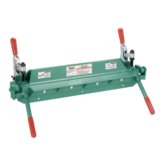
The Model T21319 24" Bending Brake is ideal for
a small workshop environment where ease of use
is important. The Model T21319 can bend up to 18
gauge (0.473 in. or 12mm) mild steel.
Figure 1. Model T21319 24" Bending Brake.
Inventory
(Figure 2)
a. Bending Brake Assembly ........................... 1
b. Clamping Angle .......................................... 1
c. Clamp Assemblies ...................................... 2
d. Breaker Bar levers ..................................... 2
e. hardware Bag (not shown)
— hex Bolts M10-1.25 x 30 ........................ 4
— hex nuts M10 ........................................ 4
— lock Washers 10mm ............................. 4
d
Figure 2. inventory.
WarnIng: no portIon oF thIs manual may be reproduced In any shape
or Form WIthout the WrItten approval oF grIzzly IndustrIal, Inc.
A
B
C
CopyrighT © MArCh, 2009 By grizzly indusTriAl, inC.
#JB11595 prinTed in ChinA
model t21319
24" bendIng braKe
InstructIon sheet
assembly
to assemble your bending brake:
1.
securely mount the bending brake assembly
to a workbench or other stable surface using
8mm hex bolts, flat washers, lock washers
and hex nuts. Mounting hole locations are
indicated in Figure 3.
Figure 3. Mounting hole locations (right side of
bending brake not shown).
2.
place the clamping angle on the bending
brake assembly.
3.
Mount each clamp assembly as shown in
Figure 4 on the next page. ensure that each
adjustment set screw shown in Figure 4 is
towards the outside of the bending brake
assembly. secure with hex bolts, lock wash-
ers and hex nuts.
Advertisement

Related Manuals for Grizzly Bending Brake T21319


Summary of Contents for Grizzly Bending Brake T21319
- Page 1 Figure 2. inventory. CopyrighT © MArCh, 2009 By grizzly indusTriAl, inC. WarnIng: no portIon oF thIs manual may be reproduced In any shape or Form WIthout the WrItten approval oF grIzzly IndustrIal, Inc. model t21319 24" bendIng braKe InstructIon sheet...
- Page 2 Adjusting nuts Clamping set screw Figure 4. Clamp installation. screw the two breaker bar levers into the breaker bar holes, as shown in Figure 5. Figure 5. Breaker bar lever installation. t21319 breakdown and parts list REF PART # DESCRIPTION PT21319001 CLAMP PSS39M SET SCREW M10-1.5 X 50...