AEG 69802 G Operating Instructions Manual
Hide thumbs
Also See for 69802 G:
- Brochure & specs (12 pages) ,
- Operating instructions manual (24 pages)
Table of Contents
Advertisement
Quick Links
Advertisement
Table of Contents

Related Manuals for AEG 69802 G


Summary of Contents for AEG 69802 G
- Page 1 69802 G Operating Instructions Gas hob...
-
Page 2: Important Safety Information
Important Safety Information You MUST read these warnings carefully before installing or using the hob. If you need assistance, contact our Customer Care Department on 08705 350350 Installation This appliance must be installed and serviced by a competent person as stated in the Gas Safety ( Installation and Use) Regulations Current Editions and the IEE Wiring Regulations. - Page 3 it has been installed. Ensure there is a continuous air supply, keeping air vents in good condition or installing a cooker hood with a venting hose. When using the hob for a long period time, the ventilation should be improved, by opening a window or increasing the extractor speed.
-
Page 4: Table Of Contents
Contents Important Safety Information ................2 Instructions for the User ..................5 Description of the Hob ....................5 Operation ........................6 Maintenance and Cleaning ..................7 Something Not Working? ................... 9 Instructions for the Installer ................10 Engineer technical data ................... 10 Important safety requirements ................. -
Page 5: Instructions For The User
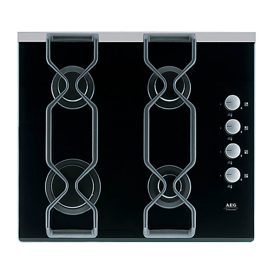
Description of the Hob 1. Hob Top 2. Rapid Burner 3. Semi-rapid Burners 4. Auxiliary Burner 5. Control knob for back right burner (semi-rapid) 6. Control knob for back left burner (semi-rapid) 7. Control knob for front left burner (rapid) 8. -
Page 6: Operation
Operation Hob burners To light a burner: Push in the relevant control knob and turn it to maximum position. A - Burner cap Upon ignition, keep the knob B - Burner crown pushed down about 5 seconds. C - Ignition electrode This will allow... -
Page 7: Maintenance And Cleaning
Maintenance and Cleaning Before any maintenance or cleaning can be carried out, you must DISCONNECT the hob from the electricity supply. The hob is best cleaned whilst it is still warm, as spillage can be removed more easily than if it is left to cool. -
Page 8: The Burners
The Burners The burner caps and crowns can be removed for cleaning. Wash the burner caps and crowns using hot soapy water, and remove marks with a mild paste cleaner. A well moistened soap impregnated steel wool pad can be used with caution, if the marks are particularly difficult to remove. -
Page 9: Something Not Working
Something Not Working? If the hob is not working correctly, please carry out the following checks before contacting your local Service Force Centre. SYMPTOM SOLUTION There is no spark when lighting the Check that the unit is plugged in and the electrical supply is switched on Check that the RCCB has not tripped (if fitted) -
Page 10: Instructions For The Installer
Instructions for the Installer Instructions for the Installer Engineer technical data OVERALL DIMENSIONS Width: 580 mm. Depth: 510 mm. Height: 88 mm. CUT OUT DIMENSIONS Width: 550 mm. Depth: 470 mm. Thickness: 30 mm. SUPPLY CONNECTIONS Gas: RC 1/2 inch (1/2 inch male) Rear right hand corner Electric: 230 V 50 Hz supply, 3 core flexible cable with non rewireable plug fitted with a 3 amp cartridge fuse. -
Page 11: Important Safety Requirements
Instructions for the Installer BURNER RAPID SEMI-RAPID AUXILIARY (large) (medium) (small) TYPE OF GAS POSITION NOMINAL THERMAL POWER 2 . 9 0.75 1 . 9 0.45 1 . 0 0.33 NATURAL GAS NOMINAL FLOW 20 mbar VALUE = RATE 0.276 0.062 0.181 0.043... -
Page 12: Location
Instructions for the Installer Location The hob may be located in a kitchen, a kitchen/diner or bed sitting room, but not in a bathroom or shower room. Before making the cut out in the worktop ensure that there is a minimum distance of 55 mm. -
Page 13: Installation
Instructions for the Installer Installation IMPORTANT This hob must be installed by a competent person to the relevant Gas Standards. Any gas installation must be carried out by a registered competent person. The manufacturer will not accept liability, should the above instructions or any of the other safety instructions incorporated in this book be ignored. -
Page 14: Gas Connection
Instructions for the Installer Gas Connection Connection to the gas supply should be with either rigid or semi-rigid pipe, i.e. steel or copper. The connection should be suitable for connecting to RC 1/2 (1/2 BSP male thread). When the final connection has been made, it is essential that a thorough leak test is carried out on the hob and installation. -
Page 15: Cut Out Size
Instructions for the Installer Cut Out Size The dimensions of the cut-out are given in the diagram. Building In Building over a cupboard or drawer If the hob is to be installed above a cupboard or drawer it will be necessary to fit a heat resistant board below the base of the hob on the underside of the work surface. -
Page 16: Building Over A Kitchen Unit With Door
Instructions for the Installer Building over a kitchen unit with door Proper arrangements must be taken in designing the furniture unit, in order to avoid any contact with the bottom of the hob which can be heated when it is operated. -
Page 17: Electrical Connections
Instructions for the Installer Electrical connections Any electrical work required to install this hob should be carried out by a qualified electrician or competent person, in accordance with the current regulations. THIS HOB MUST BE EARTHED. The manufacturer declines any liability should these safety measures not be observed. This hob is designed to be connected to a 230 V 50 Hz AC electrical supply. -
Page 18: Wiring Diagram
Instructions for the Installer Permanent Connection In the case of a permanent connection, it is necessary that you install a double pole switch between the hob and the electricity supply (mains), with a minimum gap of 3 mm. between the switch contacts and of a type suitable for the required load in compliance with the current electric regulations. -
Page 19: Fault Finding
Instructions for the Installer Fault Finding Blue Brown Green Yellow Preliminary Electrical Systems Check START Isolate appliance and carry out: Blue A: Earth Continuity Green Brown check. Yellow Carry out: Carry out: D: Resistance to C: Polarity check. Earth check. Has inlet fuse blown? Electricity supply should now be... - Page 20 Instructions for the Installer A. EARTH CONTINUITY CHECK Appliance must be electrically disconnected - meter set on Ω (Ohms) x 1 scale and adjust zero if necessary. — Test leads from any appliance earth point to earth pin on plug. Resistance should be less than 0.1 Ω...
- Page 21 Instructions for the Installer Ignition System / Gas Ignition Check gas supply at Ignitor does not spark burner Check plug top fuse and Light burner manually replace if necessary Check by pass simmer Check polarity and earth adjusted continuity of supply point Check fitting of Check position of the Check earth continuity...
-
Page 22: Commissioning
Instructions for the Installer Commissioning When the hob has been fully installed it will be necessary to check the minimum flame setting. To do this, follow the procedure below. # # # # # 1) Turn the gas tap to the MAX position and ignite. 2) Set the gas tap to the MIN flame position then turn the control knob from MIN to MAX several times. -
Page 23: Conversion From Natural Gas To Lpg
Instructions for the Installer Conversion from Natural Gas to LPG IMPORTANT The replacement/conversion of the gas hob should only be undertaken by a competent person. It is important to note that this model is designed for use with natural gas but can be converted for use with butane or propane gas providing the correct injectors are fitted and the gas rate is adjusted to suit. -
Page 24: Guarantee Conditions
Guarantee Conditions Standard guarantee conditions We, AEG-Electrolux, undertake that if within 12 months of the date of the purchase this AEG- Electrolux appliance or any part thereof is pro-ved to be defective by reason only of faulty workmanship or materials, we will, at our option repair or replace the same FREE OF CHARGE for labour, materials or carriage on condition that: •... -
Page 25: Service And Spare Parts
Service Force Centre and further informa- tion about Service Force, please visit the website at www.serviceforce.co.uk For Customer Services in the Republic of Ireland please contact us at the address below: AEG-Electrolux Electrolux Groupl (Irl) Ltd Long Mile Road Dublin 12 Republic of Ireland Tel +353 (0) 1 4090 754 Email service.eid@electrolux.ie... -
Page 26: European Guarantee
European Guarantee This appliance is guaranteed by Electrolux in each of the countries listed at the back of this user manual, for the period specified in the appliance guarantee or otherwise by law. If you move from one of these countries to another of the countries listed be-low the appliance guarantee will move with you subject to the following qualificati-ons: The appliance guarantee starts from the date you first purchased the appliance which •... - Page 28 www.aeg-electrolux.co.uk...