GE 489 Instruction Manual
Generator management relay
Hide thumbs
Also See for 489:
- Instruction manual (314 pages) ,
- Communications manual (78 pages) ,
- Instruction manual (38 pages)
Table of Contents
Advertisement
Quick Links
Download this manual
See also:
Instruction Manual
g
GE Multilin
215 Anderson Avenue, Markham, Ontario
Canada L6E 1B3
Tel: (905) 294-6222 Fax: (905) 294-8512
Internet: http://www.GEindustrial.com/multilin
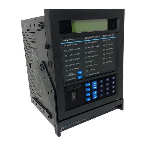
GENERATOR MANAGEMENT RELAY
SELECT CURVE STYLE:
Voltage Dependent
489 STATUS
GENERATOR STATUS OUTPUT RELAYS
489 IN SERVICE
BREAKER OPEN
SETPOINT ACCESS
BREAKER CLOSED
COMPUTER RS232
HOT STATOR
COMPUTER RS485
NEG. SEQUENCE
AUXILIARY RS485
GROUND
ALT. SETPOINTS
LOSS OF FIELD
RESET
VT FAILURE
POSSIBLE
RESET
MESSAGE
BREAKER FAILURE
NEXT
PROGRAM PORT
SETPOINT
MESSAGE
ACTUAL
ESCAPE
VALUE
ENTER
g
TM
489
Generator Management Relay
489
Instruction Manual
489 Firmware Revision: 32I151A8.000
489PC Software Revision: 1.5X
Manual P/N: 1601-0071-EA (GEK-106290B)
Copyright © 2006GE Multilin
R1 TRIP
R2 AUXILIARY
R3 AUXILIARY
R4 AUXILIARY
R5 ALARM
R6 SERVICE
7
8
9
4
5
6
1
2
3
.
0
HELP
808754E4.CDR
GE Industrial Systems
®
Manufactured under an
ISO9001 Registered system.
Advertisement
Table of Contents

Related Manuals for GE 489


Summary of Contents for GE 489
- Page 1 215 Anderson Avenue, Markham, Ontario Canada L6E 1B3 Tel: (905) 294-6222 Fax: (905) 294-8512 Internet: http://www.GEindustrial.com/multilin GENERATOR MANAGEMENT RELAY Instruction Manual 489 Firmware Revision: 32I151A8.000 489PC Software Revision: 1.5X Manual P/N: 1601-0071-EA (GEK-106290B) Copyright © 2006GE Multilin SELECT CURVE STYLE: Voltage Dependent...
-
Page 3: Table Of Contents
1.1 OVERVIEW 1.1.1 Description ... 1-1 1.1.2 Ordering ... 1-3 1.1.3 Other Accessories... 1-3 1.2 SPECIFICATIONS 1.2.1 489 Specifications ... 1-4 2.1 MECHANICAL 2.1.1 Description ... 2-1 2.1.2 Product Identification... 2-2 2.1.3 Installation ... 2-3 2.1.4 Unit Withdrawal and Insertion ... 2-3 2.1.5... - Page 4 RTDs 7 to 10...4-51 4.9.4 RTD 11 ...4-52 4.9.5 RTD 12 ...4-53 4.9.6 Open RTD Sensor ...4-54 4.9.7 RTD Short/Low Temperature...4-54 4.10 S9 THERMAL MODEL 4.10.1 489 Thermal Model ...4-55 4.10.2 Model Setup...4-56 4.10.3 Thermal Elements...4-68 489 Generator Management Relay GE Multilin...
- Page 5 5.5.3 Timers ... 5-22 5.6 A5 EVENT RECORDER 5.6.1 Event Recorder ... 5-23 5.7 A6 PRODUCT INFO 5.7.1 489 Model Info ... 5-25 5.7.2 Calibration Info ... 5-25 5.8 DIAGNOSTICS 5.8.1 Diagnostic Messages ... 5-26 5.8.2 Flash Messages ... 5-27 6.1 MODBUS PROTOCOL...
- Page 6 Reactive Power Accuracy ...7-11 7.3.4 Voltage Phase Reversal Accuracy ...7-12 7.3.5 Injection Test Setup #2 ...7-12 7.3.6 GE Multilin HGF Ground Accuracy ...7-13 7.3.7 Neutral Voltage (3rd Harmonic) Accuracy ...7-13 7.3.8 Phase Differential Trip Accuracy ...7-14 7.3.9 Injection Test Setup #3 ...7-15 7.3.10...
- Page 7 IAC Curves...B-6 B.1.4 IEC Curves...B-10 C.1 REVISION HISTORY C.1.1 Change Notes ...C-1 C.1.2 Changes Since Last Revision ...C-1 C.2 EU DECLARATION OF CONFORMITY C.2.1 EU declaration of conformity ...C-2 C.3 WARRANTY INFORMATION C.3.1 GE Multilin Warranty ...C-3 489 Generator Management Relay...
- Page 8 TABLE OF CONTENTS 489 Generator Management Relay GE Multilin...
-
Page 9: Introduction
Fault diagnostics are provided through pretrip data, event record, waveform capture, and statistics. Prior to issuing a trip, the 489 takes a snapshot of the measured parameters and stores them in a record with the cause of the trip. This pre-trip data may be viewed using the key before the trip is reset, or by accessing the last trip data in actual values page 1. - Page 10 Electrical Lockout Power metering is a standard feature in the 489. The table below outlines the metered parameters available to the operator or plant engineer either through the front panel or communications ports. The 489 is equipped with three fully functional and independent communications ports.
-
Page 11: Ordering
The control power and analog output range must also be specified at the time of order. There are two ground CT inputs: one for the GE Multilin HGF core balance CT and one for a ground CT with a 1 A secondary (may also be used to accom- modate 5 A secondary). -
Page 12: Specifications
Type: Analog Input Supply: Sampling Interval: COMMUNICATIONS PORTS RS232 Port: RS485 Ports: 489 Generator Management Relay 1 INTRODUCTION 1.2.1 489 SPECIFICATIONS 1.00 to 240.00:1 in steps of 0.01 200 V AC (full-scale) 0.02 to 1.00 × Full Scale ±0.5% of Full Scale 280 V AC >... - Page 13 I, Mvar, MW, MVA demands Torque OUTPUT RELAYS Relay contacts must be considered unsafe to touch when the 489 is energized! If the output relay con- tacts are required for low voltage accessible applica- WARNING tions, it is the customer's responsibility to ensure proper insulation levels.
- Page 14 Pick- up Level: Curve Shapes: Time Delay: Pickup Accuracy: Timing Accuracy: 489 Generator Management Relay 1 INTRODUCTION 0.05 to 1.00 × CT in steps of 0.01 Dual Slope 0 to 100 cycles in steps of 1 as per Phase Current Inputs +50 ms at 50/60 Hz or ±0.5% total time...
- Page 15 Ambient Operating Temperature: –40°C to +60°C Ambient Storage Temperature: 40°C to +80°C. Humidity: Altitude: Pollution Degree: 489 Generator Management Relay 1.2 SPECIFICATIONS 0 to 15000 s in steps of 1 0.02 to 0.99 × rated MW 0.2 to 120.0 s in steps of 0.1 see power metering ±100 ms or ±0.5% of total time...
- Page 16 FILTER GROUND Shipping Weight: CERTIFICATION ISO: CSA: 489 Generator Management Relay 1 INTRODUCTION 215.315 Per IEC 255-5 and ANSI/IEEE C37.90. 2.0 kV for 1 minute from relays, CTs, VTs, power supply to Safety Ground IEC255-5 500 V DC, from relays, CTs,...
-
Page 17: Installation
2 INSTALLATION 2.1MECHANICAL The 489 is packaged in the standard GE Multilin SR series arrangement, which consists of a drawout unit and a companion fixed case. The case provides mechanical protection to the unit, and is used to make permanent connections to all external equipment. -
Page 18: Product Identification
2.1 MECHANICAL Each 489 unit and case are equipped with a permanent label. This label is installed on the left side (when facing the front of the relay) of both unit and case. The case label details which units can be installed. -
Page 19: Unit Withdrawal And Insertion
2 INSTALLATION The 489 case, alone or adjacent to another SR unit, can be installed in a standard 19-inch rack panel (see Figure 2–1: 489 Dimensions on page 2–1). Provision must be made for the front door to swing open without interference to, or from, adja- cent equipment. - Page 20 When the unit is fully inserted, the latch will be heard to click, locking the handle in the final position. Figure 2–6: ROTATE HANDLE TO STOP POSITION Figure 2–7: SLIDE UNIT OUT OF CASE 489 Generator Management Relay 2 INSTALLATION GE Multilin...
-
Page 21: Terminal Locations
2 INSTALLATION 2.1 MECHANICAL 2.1.5 TERMINAL LOCATIONS Figure 2–8: TERMINAL LAYOUT GE Multilin 489 Generator Management Relay... - Page 22 2.1 MECHANICAL Table 2–1: 489 TERMINAL LIST TERMINAL DESCRIPTION RTD #1 HOT RTD #1 COMPENSATION RTD RETURN RTD #2 COMPENSATION RTD #2 HOT RTD #3 HOT RTD #3 COMPENSATION RTD RETURN RTD #4 COMPENSATION RTD #4 HOT RTD #5 HOT...
-
Page 23: Electrical
2 INSTALLATION 2.2 ELECTRICAL 2.2ELECTRICAL 2.2.1 TYPICAL WIRING DIAGRAM Figure 2–9: TYPICAL WIRING DIAGRAM GE Multilin 489 Generator Management Relay... -
Page 24: General Wiring Considerations
The information in this section will cover the important aspects of interconnections, in the general areas of instru- ment transformer inputs, other inputs, outputs, communications and grounding. See Figure 2–8: Terminal Layout and Table 2–1: 489 Terminal List for terminal arrangement, and Figure 2–9: Typical Wiring Diagram for typical connections. Figure 2–10: TYPICAL WIRING (DETAIL) -
Page 25: Control Power
There are no internal ground connections on the CT inputs. Each phase CT circuit is shorted by automatic mecha- nisms on the 489 case if the unit is withdrawn. The phase CTs should be chosen such that the FLA is no less than 50% of the rated phase CT primary. - Page 26 The 1 A tap is used for 1 A or 5 A secondary CTs in either core balance or residual ground configurations. If the 1 A tap is used, the 489 measures up to 20 A secondary with a maximum ground CT ratio of 10000:1.
-
Page 27: Voltage Inputs
CAUTION Terminals are provided on the 489 for the input of four 0 to 1 mA, 0 to 20 mA, or 4 to 20 mA current signals (field program- mable). This current signal can be used to monitor any external quantity such as: vibration, pressure, field current, etc. The four inputs share one common return. -
Page 28: Analog Outputs
The analog output circuitry is isolated as a group with the Analog Input circuitry and the RTD circuitry. Only one ground ref- erence should be used for the three circuits. Transorbs limit this isolation to ±36 V with respect to the 489 safety ground. -
Page 29: Output Relays
489 is drawn out, no trip or alarm occurs. The R6 Service output will however indicate that the 489 has been drawn out. Each output relay has an LED indicator on the 489 front panel that comes on while the associated relay is in the operated state. -
Page 30: Rs485 Communications Ports
2.2 ELECTRICAL Two independent two-wire RS485 ports are provided. Up to 32 489 relays can be daisy-chained together on a communica- tion channel without exceeding the driver capability. For larger systems, additional serial channels must be added. It is also possible to use commercially available repeaters to increase the number of relays on a single channel to more than 32. -
Page 31: Dielectric Strength
2.2.13 DIELECTRIC STRENGTH It may be required to test a complete motor starter for dielectric strength (“flash” or hi-pot”) with the 489 installed. The 489 is rated for 1.9 kV AC for 1 second or 1.6 kV AC for 1 minute (per UL 508) isolation between relay contacts, CT inputs, VT inputs, trip coil supervision, and the safety ground terminal G12. - Page 32 2.2 ELECTRICAL 2 INSTALLATION 2-16 489 Generator Management Relay GE Multilin...
-
Page 33: User Interfaces
489 IN SERVICE: Indicates that control power is applied, all monitored input/output and internal systems are OK, the 489 has been programmed, and is in protection mode, not simulation mode. When in simulation or testing mode, the LED indicator will flash. -
Page 34: Rs232 Program Port
489PC software. Local interrogation of setpoints and actual values is also possible. New firmware may be downloaded to the 489 flash memory through this port. Upgrading the relay firmware does not require a hardware EEPROM change. - Page 35 ENTER c) ENTERING +/– SIGNS The 489 does not have a ‘+’ or ‘–’ key. Negative numbers may be entered in one of the following two ways: • Press the keys the scroll through the setpoint range, including any negative numbers.
-
Page 36: Software Interface
Windows 3.1, Windows 3.11 for Workgroups, Windows 95/98, or Windows NT. Windows 3.1 users must ensure that SHARE.EXE is installed. 489PC may be installed from either the GE Multilin Products CD or the GE Multilin website at www.GEindus- NOTE trial.com/multilin. If you are using legacy equipment without web access or a CD, 3.5” floppy disks can be ordered from the factory. -
Page 37: Installation/Upgrade
If 489PC is already installed, run the program and use the following procedure to check if it needs upgrading: While 489PC is running, insert the GE Multilin Products CD and allow it to autostart (alternately, load the D:\index.htm file from the CD into your default web browser), OR Go to the GE Multilin website at www.GEindustrial.com/multilin (preferred method) - Page 38 The Products CD is essentially a “snapshot” of the GE Multilin website at the date printed on the CD. As such, the proce- dures for installation from the CD or the website are identical; however, to ensure that the newest version of 489PC is installed, installation from the web is preferred.
-
Page 39: Configuration
To begin communications, click the ON button. The status section indicates the communications status. The message “489PC is now talking to a 489” is displayed when communications are established. As well, the bottom right corner of the 489PC window will indicate “Communicating.”... -
Page 40: Using 489Pc
UPGRADING THE 489 FIRMWARE Prior to downloading new firmware into the 489, it is necessary to save the 489 setpoints to a file (see Section 3.2.4: Using 489PC on page 3–8. Loading new firmware into the 489 flash memory is accomplished as follows: Ensure the computer is connected to the 489 via the front RS232 port and that communications have been estab- lished. - Page 41 The following procedure demonstrates how to load setpoints from a file: Select the File > Open menu item. 489PC will launch the Open window and list all filenames in the 489 default directory with the 489 extension. Select the setpoint file to download and click OK to continue.
- Page 42 UPGRADING SETPOINT FILES TO A NEW REVISION It may be necessary to upgrade the revision code for a previously saved setpoint file after the 489 firmware has been upgraded. Establish communications with the 489 relay.
- Page 43 Select the File > Save menu item to save the setpoint file in the new format. See Section c): Loading Setpoints from a File on page 3–9 for instructions on downloading this setpoint file to the 489. f) PRINTING SETPOINTS AND ACTUAL VALUES Use the following procedure to print a complete list of setpoint values.
-
Page 44: Trending
3.2 SOFTWARE INTERFACE Trending from the 489 can be accomplished via the 489PC program. Many different parameters can be trended and graphed at sampling periods ranging from 1 second up to 1 hour. The parameters which can be Trended by the 489PC software are:... - Page 45 Zoom In, Zoom Out left mouse button and drag the cursor line to the new location Figure 3–6: TRENDING Figure 3–7: TRENDING FILE SETUP 489 Generator Management Relay 3.2 SOFTWARE INTERFACE WAVEFORM The trended data from the 469 relay 808726A2.CDR...
- Page 46 The phase A current waveform for the last 489 trip will appear. The date and time of the trip is displayed at the top of the window. The red vertical line indicates the trigger point of the relay.
-
Page 47: Phasors
CURRENT LEVEL Displays the value and angle of the current phasors GE Multilin CURRENT PHASOR VOLTAGE PHASOR Short arrow Long arrow 808713A1.CDR Figure 3–9: PHASORS 489 Generator Management Relay 3.2 SOFTWARE INTERFACE 3.2.7 PHASORS 3-15... -
Page 48: Event Recorder
3.2 SOFTWARE INTERFACE The 489 event recorder can be viewed through the 489PC software. The event recorder stores generator and system infor- mation each time an event occurs (e.g. a generator trip). Up to 40 events can be stored, where EVENT01 is the most recent and EVENT40 is the oldest. -
Page 49: Troubleshooting
If Windows™ prevents the replacing of this file, restart the PC and replace the file before any programs are opened. Restart Windows™ for these changes to take full effect. GE Multilin 489 Generator Management Relay 3.2 SOFTWARE INTERFACE 3.2.9 TROUBLESHOOTING... - Page 50 3.2 SOFTWARE INTERFACE 3 USER INTERFACES 3-18 489 Generator Management Relay GE Multilin...
-
Page 51: Setpoints
See page 4–16. [ENTER] for more THERMAL RESET See page 4–16. [ENTER] for more DUAL SETPOINTS See page 4–16. [ENTER] for more SEQUENTIAL TRIP See page 4–17. [ENTER] for more 489 Generator Management Relay 4.1 OVERVIEW 4.1.1 SETPOINT MESSAGE MAP... - Page 52 PHASE REVERSAL ESCAPE [ENTER] for more MESSAGE UNDERFREQUENCY ESCAPE [ENTER] for more MESSAGE 489 Generator Management Relay 4 SETPOINTS See page 4–18. See page 4–18. See page 4–19. See page 4–19. See page 4–20. See page 4–24. See page 4–24.
- Page 53 [ENTER] for more THERMAL ELEMENTS See page 4–68. [ENTER] for more TRIP COUNTER See page 4–69. [ENTER] for more BREAKER FAILURE See page 4–69. [ENTER] for more TRIP COIL MONITOR See page 4–70. [ENTER] for more 489 Generator Management Relay 4.1 OVERVIEW...
- Page 54 COMM PORT MONITOR ESCAPE [ENTER] for more MESSAGE FACTORY SERVICE ESCAPE [ENTER] for more MESSAGE 489 Generator Management Relay 4 SETPOINTS See page 4–71. See page 4–72. See page 4–72. See page 4–72. See page 4–72. See page 4–74. See page 4–74.
-
Page 55: Trips / Alarms/ Control Features
TRIPS A 489 trip feature may be assigned to any combination of the four output relays: R1 Trip, R2 Auxiliary, R3 Auxiliary, and R4 Auxiliary. If a Trip becomes active, the appropriate LED (indicator) on the 489 faceplate illuminates to indicate which output relay has operated. -
Page 56: Dual Setpoints
4.1.4 DUAL SETPOINTS The 489 has dual settings for the current, voltage, power, RTD, and thermal model protection elements (setpoints pages S5 to S9). These setpoints are organized in two groups: the main group (Group 1) and the alternate group (Group 2). Only one group of settings is active in the protection scheme at a time. -
Page 57: S1 489 Setup
MESSAGE A passcode access security feature is provided with the 489. The passcode is defaulted to "0" (without the quotes) at the time of shipping. Passcode protection is ignored when the passcode is "0". In this case, the setpoint access jumper is the only protection when programming setpoints from the front panel keypad and setpoints may be altered using the RS232 and RS485 serial ports without access protection. -
Page 58: Serial Ports
The computer RS485 port is a general purpose port for connection to a DCS, PLC, or PC. The Auxiliary RS485 port may also be used as another general purpose port or it may be used to talk to Auxiliary GE Multilin devices in the future. -
Page 59: Real Time Clock
Communications for information on programming the time preload and synchronizing commands. An IRIG-B signal receiver may be connected to 489 units with hardware revision G or higher. The relay will continuously decode the time signal and set its internal time correspondingly. The “signal type” setpoint must be set to match the signal provided by the receiver. -
Page 60: Message Scratchpad
4.2 S1 489 SETUP The 489 displays default messages after a period of keypad inactivity. Up to 20 default messages can be selected for dis- play. If more than one message is chosen, they will automatically scroll at a rate determined by the... -
Page 61: Clear Data
Range: No, Yes CLEAR TRIP COUNTERS: No Range: No, Yes CLEAR EVENT RECORD: No Range: No, Yes CLEAR GENERATOR INFORMATION: No Range: No, Yes CLEAR BREAKER INFORMATION: No 489 Generator Management Relay 4.2 S1 489 SETUP 4.2.7 CLEAR DATA 4-11... -
Page 62: S2 System Setup
PHASE CT PRIMARY indicating that the 489 was never programmed. Once these values are entered, the 489 will be in service. Select the Phase CT so that the maximum fault current does not exceed 20 times the primary rating. When relaying class CTs are pur- chased, this precaution helps prevent CT saturation under fault conditions. -
Page 63: Generator Parameters
"--------", indicating they are not programmed. The 489 indicates that it was never programmed. Once these values are entered, the 489 will be in service. All elements associated with power quantities are programmed in per unit values calculated from the rated MVA and power factor. The generator full load amps (FLA) is calculated as... -
Page 64: S3 Digital Inputs
4.4S3 DIGITAL INPUTS The 489 has nine (9) digital inputs for use with external contacts. Two of the 489 digital inputs have been pre-assigned as inputs having a specific function. The Access Switch does not have any setpoint messages associated with it. The Breaker Status input, may be configured for either an 'a' or 'b' auxiliary contact. -
Page 65: General Input A To G
Range: 0.1 to 5000.0 in steps of 0.1 GENERAL INPUT A TRIP DELAY: 5.0 s is set to 0, the output relay(s) operate only while the 489 Generator Management Relay 4.4 S3 DIGITAL INPUTS 4.4.3 GENERAL INPUT A TO G 4-15... -
Page 66: Remote Reset
[ENTER] for more Once the 489 is in service, it may be tested from time to time as part of a regular maintenance schedule. The unit will have accumulated statistical information relating historically to generator and breaker operation. This information includes: last... -
Page 67: Sequential Trip
Group 2). In the event of a conflict between the setpoint or the assigned digital input, Group 2 will be activated. The LED indicator on the faceplate of the 489 POINT GROUP will indicate when the alternate setpoints are active in the protection scheme. -
Page 68: Field-Breaker Discrepancy
Range: 1 to 250 s in steps of 1 TACHOMETER TRIP ESCAPE DELAY: 1 s MESSAGE 489 Generator Management Relay 4 SETPOINTS 4.4.9 FIELD-BREAKER DISCREPANCY the Tachometer, it may not be used here. 4.4.10 TACHOMETER may be assigned to the Tachometer... -
Page 69: Waveform Capture
ASSIGN DIGITAL the Tachometer, it may not be used here. INPUT: None Range: Auxiliary a, Auxiliary b GROUND SWITCH CONTACT: Auxiliary a 489 Generator Management Relay 4.4 S3 DIGITAL INPUTS actual SPEED TACHOMETER 4.4.11 WAVEFORM CAPTURE 4.4.12 GROUND SWITCH STATUS... -
Page 70: S4 Output Relays
Obviously, when control power is lost to the 489, the output relays must be de-energized and there- fore, they will be in their non-operated state. Shorting bars in the drawout case ensure that when the 489 is drawn out, no trip or alarm occurs. -
Page 71: S5 Current Elements
4.6S5 CURRENT ELEMENTS a) DESCRIPTION The 489 inverse time overcurrent curves may be either ANSI, IEC, or GE Type IAC standard curve shapes. This allows for simplified coordination with downstream devices. If however, none of these curve shapes is adequate, the FlexCurve™... - Page 72 – – pickup pickup CONSTANTS 0.0040 0.6379 0.6200 0.0900 0.7955 0.1000 0.2078 0.8630 0.8000 0.0428 0.0609 0.6200 489 Generator Management Relay 4 SETPOINTS (EQ 4.5) ⎞ ⎟ (EQ 4.6) ⁄ ⎠ – pickup 1.7872 0.2461 –1.2885 7.9586 –0.4180 0.1947 –0.0010 0.0221...
- Page 73 To enter a custom FlexCurve™, read off each individual point from a time overcurrent coordination drawing and enter it into a table as shown. Then transfer each individual point to the 489 using either the 489PC software or the front panel keys and display.
-
Page 74: Overcurrent Alarm
CT measurements (Ia, Ib, Ic). It may be set much more sensitive than the differential element to detect high impedance phase faults. Since the breaker auxiliary contacts wired to the 489 Breaker Status input may not operate at exactly the same time as the main breaker contacts, the time delay should be coordinated with the difference of the operation times. -
Page 75: Inadvertent Energization
INADVERTENT ENERGIZE O/C PICKUP: 0.05 x CT Range: 0.50 to 0.99 × Rated Voltage in steps of 0.01 INADVERTENT ENERGIZE PICKUP: 0.50 x Rated V 250 ms 489 Generator Management Relay 4.6 S5 CURRENT ELEMENTS 4.6.4 INADVERTENT ENERGIZATION Operate 808731A1.CDR 4-25... -
Page 76: Voltage Restrained Phase Overcurrent
The magnitude of each phase current measured at the output CTs is used to time out against an inverse time curve. The 489 inverse time curve for this element may be either ANSI, IEC, or GE Type IAC standard curve shapes. -
Page 77: Negative Sequence Overcurrent
4 SETPOINTS The 489 phase overcurrent restraint voltages and restraint characteristic are shown below: Phase Overcurrent Restraint Voltages: CURRENT VOLTAGE 808792A3.CDR Figure 4–2: VOLTAGE RESTRAINT CHARACTERISTIC PATH: SETPOINTS S5 CURRENT ELEMENTS ð NEGATIVE SEQUENCE ENTER ð [ENTER] for more ESCAPE... - Page 78 = time in seconds when I The 489 has a definite time alarm and inverse time overcurrent curve trip to protect the generator rotor from overheating due to the presence of negative sequence currents. Pickup values are negative sequence current as a percent of generator rated full load current.
-
Page 79: Ground Overcurrent
The 489 ground overcurrent feature consists of both an alarm and a trip element. The magnitude of measured ground cur- rent is used to time out against the definite time alarm or inverse time curve trip. The 489 inverse time curve for this element may be either ANSI, IEC, or GE Type IAC standard curve shapes. -
Page 80: Phase Differential
[ENTER] for more The 489 differential element consists of the well known, dual slope, percent restraint characteristic. A differential signal is derived from the phasor sum of the currents on either side of the machine. A restraint signal is derived from the average of the magnitudes of these two currents. -
Page 81: Ground Directional
Range: 0.05 to 20.00 × CT in steps of 0.01 GROUND DIR. TRIP PICKUP: 0.05 x CT Range: 0.1 to 120.0 sec. in steps of 0.1 GROUND DIR. TRIP DELAY: 3.0 sec. 489 Generator Management Relay 4.6 S5 CURRENT ELEMENTS 808790A2.CDR 4.6.9 GROUND DIRECTIONAL 4-31... -
Page 82: High-Set Phase Overcurrent
, below 2.0 V secondary. The pickup level for the ground current elements is programmable as a multiple of the CT. The 50:0.025 CT is intended for very sensitive detection of ground faults and its nominal CT rating for the 489 is 50:0.025. NOTE For example, if the ground CT is 50:0.025, a pickup of 0.20 would be 0.20 x 5 = 1 A primary. -
Page 83: S6 Voltage Elements
Range: 0.0 to 999.9 s in steps of 0.1 UNDERVOLTAGE CURVE RESET RATE: 1.4 s Range: Curve, Definite Time UNDERVOLTAGE CURVE ELEMENT: Curve 1000 (EQ 4.18) setpoint setpoint 489 Generator Management Relay 4.7 S6 VOLTAGE ELEMENTS 4.7.1 UNDERVOLTAGE Multiples of Undervoltage Pickup 808742A1.CDR 4-33... -
Page 84: Overvoltage
Range: 0.0 to 999.9 s in steps of 0.1 OVERVOLTAGE CURVE ESCAPE RESET RATE: 1.4 s MESSAGE Range: Curve, Definite Time OVERVOLTAGE CURVE ESCAPE ELEMENT: Curve MESSAGE 1000 (EQ 4.19) pickup setpoint setpoint 489 Generator Management Relay 4 SETPOINTS 4.7.2 OVERVOLTAGE Multiples of Overvoltage Pickup 808741A1.CDR GE Multilin... -
Page 85: Volts/Hertz
The reset 1000 --- - > Pickup setpoint 0.01 1.00 1.20 Multiples of Volts/Hertz Pickup 489 Generator Management Relay 4.7 S6 VOLTAGE ELEMENTS 4.7.3 VOLTS/HERTZ 1.40 1.60 1.80 2.00 808743A1-X1.CDR 4-35... -
Page 86: Phase Reversal
[ENTER] for more The 489 can detect the phase rotation of the three phase voltages. A trip will occur within 200 ms if the Phase Reversal fea- ture is turned on, the generator is offline, each of the phase-phase voltages is greater than 50% of the generator rated phase-phase voltage and the phase rotation is not the same as the setpoint. -
Page 87: Underfrequency
TRIP DELAY1: 60.0 s Range: 20.00 to 60.00 Hz in steps of 0.01 UNDERFREQUENCY TRIP LEVEL2: 58.00 Hz Range: 0.1 to 5000.0 s in steps of 0.1 UNDERFREQUENCY TRIP DELAY2: 30.0 s 489 Generator Management Relay 4.7 S6 VOLTAGE ELEMENTS 4.7.5 UNDERFREQUENCY 4-37... -
Page 88: Overfrequency
Range: 25.01 to 70.00 Hz in steps of 0.01 OVERFREQUENCY ESCAPE TRIP LEVEL2: 62.00 Hz MESSAGE Range: 0.1 to 5000.0 s in steps of 0.1 OVERFREQUENCY ESCAPE TRIP DELAY2: 30.0 s MESSAGE 489 Generator Management Relay 4 SETPOINTS 4.7.6 OVERFREQUENCY GE Multilin... -
Page 89: Neutral Overvoltage (Fundamental)
RESET RATE: 0.0 Range: Curve, Definite Time NEUTRAL O/V TRIP ELEMENT: Definite Time 1000 (EQ 4.20) setpoint setpoint 489 Generator Management Relay 4.7 S6 VOLTAGE ELEMENTS 0.1 to 120.0 s in steps of 0.1 Multiples of Overvoltage Pickup 808741A1.CDR 4-39... -
Page 90: Neutral Overvoltage (3Rd Harmonic)
4.7 S6 VOLTAGE ELEMENTS GROUNDING SWITCH TO Vneutral OF EACH 489 If the ground directional element is enabled, the Neutral Overvoltage element should be coordinated with it. In cases of paralleled generator grounds through the same point, with individual ground switches, per sketch below, it is recommended to use a ground switch status function to prevent maloperation of the element. - Page 91 -------------------------------------- - 3 ⁄ The 489 tests the following permissives prior to testing the basic operating equation to ensure that V surable magnitude for an unfaulted generator: ′ 0.25 volts >...
-
Page 92: Loss Of Excitation
∠ θ --------------- – × CT Ratio primary -------------------------------------------------- ondary VT Ratio 489 Generator Management Relay 4 SETPOINTS 4.7.9 LOSS OF EXCITATION ENABLE VOLTAGE SUPERVISION is "Yes" and an offset of set- VOLTAGE LEVEL (EQ 4.23) (EQ 4.24) GE Multilin... -
Page 93: Distance Element
REACH: 15.0 Ωsec Range: 50 to 85° in steps of 1 ZONE #2 ANGLE: 75° Range: 0.0 to 150.0 s in steps of 0.1 ZONE #2 TRIP DELAY: 2.0 s 489 Generator Management Relay 4.7 S6 VOLTAGE ELEMENTS 4.7.10 DISTANCE ELEMENT 4-43... - Page 94 VTFF element. In order to prevent nuisance tripping the elements require a mini- mum phase current of 0.05 x CT. Neutral End CT 4-44 Protection Zone 1 Protection Zone 2 Terminal VT Relay Figure 4–8: DISTANCE ELEMENT SETUP 489 Generator Management Relay 4 SETPOINTS 808740A1.CDR GE Multilin...
-
Page 95: S7 Power Elements
Generation of power will be displayed on the 489 as positive watts. By convention, an induction generator normally requires reactive power from the system for excitation. This is displayed on the 489 as negative vars. A synchronous generator on the other hand has its own source of excitation and can be operated with either lagging or leading power factor. This is dis- played on the 489 as positive vars and negative vars, respectively. -
Page 96: Reactive Power
NEGATIVE Mvar TRIP ESCAPE DELAY: 20.0 s MESSAGE – × × Rated PF 489 Generator Management Relay 4 SETPOINTS 4.8.2 REACTIVE POWER Note: Lagging vars, overexcited Note: Leading vars, underexcited Note: Lagging vars, overexcited Note: Leading vars, underexcited – 0.85 52.67 Mvars... -
Page 97: Reverse Power
Range: 0.02 to 0.99 × Rated MW in steps of 0.01 REVERSE POWER TRIP LEVEL: 0.05 x Rated MW Range: 0.2 to 120.0 s in steps of 0.1 REVERSE POWER TRIP DELAY: 20.0 s 489 Generator Management Relay 4.8 S7 POWER ELEMENTS 4.8.3 REVERSE POWER 4-47... -
Page 98: Low Forward Power
LOW FWD POWER TRIP ESCAPE LEVEL: 0.05 x Rated MW MESSAGE Range: 0.2 to 120.0 s in steps of 0.1 LOW FWD POWER TRIP ESCAPE DELAY: 20.0 s MESSAGE 489 Generator Management Relay 4 SETPOINTS 4.8.4 LOW FORWARD POWER GE Multilin... -
Page 99: S8 Rtd Temperature
233.97 291.96 243.30 303.46 252.88 315.31 262.76 327.54 272.94 340.14 283.45 353.14 294.28 366.53 305.44 489 Generator Management Relay 4.9 S8 RTD TEMPERATURE 4.9.1 RTD TYPES 10 Ω CU 7.10 7.49 7.88 8.26 8.65 9.04 9.42 9.81 10.19 10.58 10.97 11.35... -
Page 100: Rtds 1 To 6
Range: Any combination of Relays 1 to 4 ASSIGN TRIP ESCAPE RELAYS (1-4): 1--- MESSAGE Range: 1 to 250°C in steps of 1 RTD #1 TRIP ESCAPE TEMPERATURE: 155°C MESSAGE 489 Generator Management Relay 4 SETPOINTS 4.9.2 RTDS 1 TO 6 GE Multilin... -
Page 101: Rtds 7 To 10
Range: Any combination of Relays 1 to 4 ASSIGN TRIP RELAYS (1-4): 1--- Range: 1 to 250°C in steps of 1 RTD #7 TRIP TEMPERATURE: 90°C 489 Generator Management Relay 4.9 S8 RTD TEMPERATURE 4.9.3 RTDS 7 TO 10 4-51... -
Page 102: Rtd 11
Range: Any combination of Relays 1 to 4 ASSIGN TRIP ESCAPE RELAYS (1-4): 1--- MESSAGE Range: 1 to 250°C in steps of 1 RTD #11 TRIP ESCAPE TEMPERATURE: 90°C MESSAGE 489 Generator Management Relay 4 SETPOINTS 4.9.4 RTD 11 GE Multilin... -
Page 103: Rtd 12
RTD #12 Range: Any combination of Relays 1 to 4 ASSIGN TRIP RELAYS (1-4): 1--- Range: 1 to 250°C in steps of 1 RTD #12 TRIP TEMPERATURE: 80°C 489 Generator Management Relay 4.9 S8 RTD TEMPERATURE 4.9.5 RTD 12 4-53... -
Page 104: Open Rtd Sensor
[ENTER] for more The 489 has an Open RTD Sensor Alarm. This alarm will look at all RTDs that have either an alarm or trip programmed and determine if an RTD connection has been broken. Any RTDs that do not have a trip or alarm associated with them will be ignored for this feature. -
Page 105: S9 Thermal Model
4.10S9 THERMAL MODEL The thermal model of the 489 is primarily intended for induction generators, especially those that start on the system bus in the same manner as induction motors. However, some of the thermal model features may be used to model the heating that occurs in synchronous generators during overload conditions. -
Page 106: Model Setup
Range: 0.5 to 999.9 in steps of 0.1. Seen only if SAFE STALL TIME @ ESCAPE 100% VOLTAGE: 10.0 s MESSAGE 489 Generator Management Relay 4 SETPOINTS 4.10.2 MODEL SETUP A value of "0" effectively defeats this feature Seen only if ENABLE RTD BIASING is "Yes"... - Page 107 The 489 overload curve can take one of three formats, Standard, Custom Curve, or Voltage Dependent. Regardless of which curve style is selected, the 489 will retain thermal memory in the form of a register called Thermal Capacity Used. This register is updated every 50 ms using the following equation: used t where: time to trip = time taken from the overload curve at Ieq as a function of FLA.
- Page 108 4.10 S9 THERMAL MODEL 4 SETPOINTS 100000 10000 1000 1.00 0.10 1.00 1000 MULTIPLE OF FULL LOAD AMPS 806804A5.CDR Figure 4–11: 489 STANDARD OVERLOAD CURVES 4-58 489 Generator Management Relay GE Multilin...
- Page 109 91.14 182.27 273.41 364.55 455.68 546.82 637.96 729.09 820.23 911.37 1002.5 1093.6 1184.8 1275.9 1367.0 1.50 69.99 139.98 209.97 279.96 349.95 419.94 489.93 559.92 629.91 699.90 769.89 839.88 909.87 979.86 1049.9 1.75 42.41 84.83 127.24 169.66 212.07 254.49 296.90 339.32 381.73 424.15 466.56 508.98 551.39 593.81 636.22 2.00...
- Page 110 The distinct parts of the thermal limit curves now become more critical. For these conditions, it is recommended that the 489 custom curve thermal model be used. The custom overload curve allows users to program their own curves by entering trip times for 30 pre-determined current levels.
- Page 111 The protection relay must be able to distinguish between a locked rotor condition, an accelerating condition, and a running condition. The 489 voltage dependent overload curve feature is tai- lored to protect these types of machines. Voltage is monitored constantly during starting and the acceleration thermal limit curve adjusted accordingly.
- Page 112 Figure 4–14: VOLTAGE DEPENDENT OVERLOAD CURVES 4-62 (CUSTOM CURVE) 1000 Acceleration Intersect at 80%V Acceleration Intersect at 100%V 808827A3.CDR 489 Generator Management Relay 4 SETPOINTS VOLTAGE DEPENDENT OVERLOAD (ACCELERATION CURVES) GE Multilin 489 Custom Curve MULTIPLES OF FULL LOAD AMPS 808828A3.CDR...
- Page 113 4 SETPOINTS The 489 takes the information provided and create protection curves for any voltage between the minimum and 100%. For values above the voltage in question, the 489 extrapolates the safe stall protection curve to 110% voltage. This current level is calculated by taking the locked rotor current at 100% voltage and multiplying by 1.10.
- Page 114 4.10 S9 THERMAL MODEL The following curves illustrate the resultant overload protection for 80% and 100% voltage, respectively. For voltages inbe- tween these levels, the 489 shifts the acceleration curve linearly and constantly based upon the measured voltage during generator start.
- Page 115 The 489 measures the ratio of negative to positive sequence current. The thermal model may be biased to reflect the addi- tional heating that is caused by negative sequence current when the machine is running. This biasing is done by creating an equivalent heating current rather than simply using average current (I the equation shown below.
- Page 116 4.10 S9 THERMAL MODEL e) MACHINE COOLING The 489 thermal capacity used value is reduced exponentially when the motor current is below the point. This reduction simulates machine cooling. The cooling time constants should be entered for both stopped and run- ning cases (the generator is assumed to be running if current is measured or the generator is offline).
- Page 117 4 SETPOINTS f) HOT/COLD CURVE RATIO When thermal limit information is available for both a hot and cold machine, the 489 thermal model will adapt for the condi- tions if the is programmed. The value entered for this setpoint dictates the level of thermal capacity...
-
Page 118: Thermal Elements
ALARM EVENTS: Off MESSAGE Range: Off, Latched, Unlatched THERMAL MODEL ESCAPE TRIP: Off MESSAGE Range: Any combination of Relays 1 to 4 ASSIGN TRIP ESCAPE RELAYS (1-4): 1--- MESSAGE 489 Generator Management Relay 4 SETPOINTS 808721A1.CDR 4.10.3 THERMAL ELEMENTS GE Multilin... -
Page 119: Trip Counter
Range: 10 to 1000 ms in steps of 10 BREAKER FAILURE DELAY: 100 ms Range: On, Off BREAKER FAILURE ALARM EVENTS: Off 489 Generator Management Relay 4.11 S10 MONITORING 4.11.1 TRIP COUNTER is reached. The trip counter must be A4 MAINTENANCE TRIP COUNTERS 4.11.2 BREAKER FAILURE... -
Page 120: Trip Coil Monitor
TRIP COIL OPEN/CLOSED SUPERVISION "52 Open/Closed" TRIP COIL WITH MULTIPLE BREAKER AUX CONTACTS Figure 4–19: TRIP COIL SUPERVISION 489 Generator Management Relay 4 SETPOINTS 4.11.3 TRIP COIL MONITOR TRIP COIL SUPERVISION R1 TRIP CONTACT TRIP COIL TRIP COIL OPEN/CLOSED SUPERVISION "52 Open/Closed"... -
Page 121: Vt Fuse Failure
Range: Any combination of Relays 2 to 5 ASSIGN ALARM RELAYS (2-5): ---5 Range: On, Off VT FUSE FAILURE ALARM EVENTS: Off 99ms 99ms 489 Generator Management Relay 4.11 S10 MONITORING 4.11.4 VT FUSE FAILURE Block Appropriate Elements & Operate... -
Page 122: Current, Mw, Mvar, And Mva Demand
RELAYS (2-5): ---5 MESSAGE Range: 0.10 to 20.00 × Rated in steps of 0.01 MVA DEMAND ESCAPE LIMIT: 1.25 x Rated MESSAGE Range: On, Off MVA DEMAND ESCAPE ALARM EVENTS: Off MESSAGE 489 Generator Management Relay 4 SETPOINTS GE Multilin... - Page 123 4 SETPOINTS The 489 can measure the demand of the generator for several parameters (current, MW, Mvar, MVA). The demand values of generators may be of interest for energy management programs where processes may be altered or scheduled to reduce overall demand on a feeder. The generator FLA is calculated as: Generator FLA Power quantities are programmed as per unit calculated from the rated MVA and rated power factor.
-
Page 124: Pulse Output
[ENTER] for more The 489 can perform pulsed output of positive kWh and both positive and negative kvarh. Each output parameter can be assigned to any one of the alarm or auxiliary relays. Pulsed output is disabled for a parameter if the relay setpoint is selected as OFF for that pulsed output. -
Page 125: Analog Outputs 1 To 4
MESSAGE The 489 has four analog output channels (4 to 20 mA or 0 to 1 mA as ordered). Each channel may be individually config- ured to represent a number of different measured parameters as shown in the table below. The minimum value pro- grammed represents the 4 mA output. -
Page 126: Analog Inputs 1 To 4
Range: –50000 to 50000 in steps of 1 ANALOG INPUT1 ESCAPE MAXIMUM: 100 MESSAGE Range: 0 to 5000 sec. in steps of 1 BLOCK ANALOG INPUT1 ESCAPE FROM ONLINE: 0 s MESSAGE 489 Generator Management Relay 4 SETPOINTS DEFAULT 1.25 1.25 1.25 1.25 1.25 1.25 1.25 1.25... - Page 127 Range: Over, Under ANALOG INPUT1 TRIP PICKUP: Over Range: 0.1 to 300.0 s in steps of 0.1 ANALOG INPUT1 TRIP DELAY: 0.1 s 489 Generator Management Relay 4.12 S11 ANALOG I/O ANALOG INPUT 1 UNITS above ANALOG INPUT 1 UNITS above...
-
Page 128: Simulation Mode
489 measures current or control power is cycled, the If the 489 is to be used for training, it might be desirable to allow all parameter averages, statistical information, and event recording to update when operating in simulation mode. If however, the 489 has been installed and will remain installed on a specific generator, it might be desirable assign a digital input to Test Input and to short that input to prevent all of this data from being corrupted or updated. -
Page 129: Pre-Fault Setup
MESSAGE ESCAPE MESSAGE ESCAPE MESSAGE The values entered under Pre-Fault Values will be substituted for the measured values in the 489 when the is "Simulate Pre-Fault". MODE GE Multilin Range: 0.00 to 20.00 × CT in steps of 0.01 PRE-FAULT Iphase OUTPUT: 0.00 x CT... -
Page 130: Fault Setup
PATH: SETPOINTS S12 TESTING FAULT SETUP ð [ENTER] for more The values entered here are substituted for the measured values in the 489 when the 4-80 FAULT SETUP Range: 0.00 to 20.00 × CT in steps of 0.01 ð FAULT Iphase ENTER OUTPUT: 0.00 x CT... -
Page 131: Test Output Relays
The appropriate relay indicator will illuminate at that time. Selecting "Disabled" places the out- put relays back in service. If the 489 measures current or control power is cycled, the force operation of relays setpoint will automatically become disabled and the output relays will revert back to their normal states. -
Page 132: Comm Port Monitor
Any of the three communications ports may be monitored. After the communications buffers are cleared, any data received from the monitored communications port is stored in Rx1 and Rx2. If the 489 transmits a message, it appears in the Tx1 and Tx2 buffers. In addition to these buffers, there is a message indicating the status of the last received message. - Page 133 Actual value messages are organized into logical groups, or pages, for easy reference, as shown below. All actual value messages are illustrated and described in blocks throughout this chapter. All values shown in these message illustrations assume that no inputs (besides control power) are connected to the 489. ð...
-
Page 134: Overview
ENTER ð ESCAPE [ENTER] for more CALIBRATION INFO. ESCAPE [ENTER] for more MESSAGE 489 Generator Management Relay 5 ACTUAL VALUES See page 5–18. See page 5–18. See page 5–19. See page 5–20. See page 5–22. See page 5–22. See page 5–23. -
Page 135: A1 Status
489 has not yet been reset, the value reflects an integrated value of both the stator and rotor thermal capacity used. The values for USED will appear whenever the 489 thermal model picks up on the overload curve. TIME ON OVERLOAD PATH: ACTUAL VALUES... -
Page 136: Alarm Status
5.2 A1 STATUS Immediately prior to issuing a trip, the 489 takes a snapshot of generator parameters and stores them as pre-trip values; this allows for troubleshooting after the trip occurs. The cause of last trip message is updated with the current trip and the screen defaults to that message. - Page 137 ALARM: 10.00 x FLA Range: 0 to 100% FLA. Reflects the present negative- NEG. SEQ. CURRENT ALARM: 15% FLA Range: 0.00 to 200000.00 A. Seen only if the GE HGF GROUND OVERCURRENT ALARM: 5.00 A Range: 0.00 to 200000.00 A GROUND DIRECTIONAL ALARM: 5.00 A...
-
Page 138: Trip Pickups
Range: –50000 to +50000. Reflects the Analog Input 4 Name. The Analog Input level is shown here. If the 489 chassis is only partially engaged with the case, this service alarm appears after 1 sec. Secure the chassis handle to ensure that all... - Page 139 Latched Trip. PICKUP: Not Enabled Range: Not Enabled, Inactive, Timing Out, Active Trip, UNDERFREQUENCY Latched Trip. PICKUP: Not Enabled Range: Not Enabled, Inactive, Timing Out, Active Trip, OVERFREQUENCY Latched Trip. PICKUP: Not Enabled 489 Generator Management Relay 5.2 A1 STATUS...
- Page 140 ESCAPE PICKUP: Not Enabled MESSAGE Range: Not Enabled, Inactive, Timing Out, Active Trip, THERMAL MODEL ESCAPE PICKUP: Not Enabled MESSAGE 489 Generator Management Relay 5 ACTUAL VALUES Latched Trip. Latched Trip. Latched Trip. Latched Trip. Latched Trip. Latched Trip. Latched Trip.
-
Page 141: Alarm Pickups
Range: Not Enabled, Inactive, Timing Out, Active Alarm, PHASE DIFFERENTIAL Latched Alarm. PICKUP: Not Enabled Range: Not Enabled, Inactive, Timing Out, Active Alarm, GROUND DIRECTIONAL Latched Alarm. PICKUP: Not Enabled 489 Generator Management Relay 5.2 A1 STATUS 5.2.5 ALARM PICKUPS Alarm. Reflects Input Name... - Page 142 ESCAPE PICKUP: Not Enabled MESSAGE Range: Not Enabled, Inactive, Timing Out, Active Alarm, RTD #12 ESCAPE PICKUP: Not Enabled MESSAGE 489 Generator Management Relay 5 ACTUAL VALUES Latched Alarm. Latched Alarm. Latched Alarm. Latched Alarm. Latched Alarm. Latched Alarm. Latched Alarm.
- Page 143 Range: see ANALOG I/P 1 PICKUP ANALOG I/P 2 PICKUP: Not Enabled Range: see ANALOG I/P 1 PICKUP ANALOG I/P 3 PICKUP: Not Enabled Range: see ANALOG I/P 1 PICKUP ANALOG I/P 4 PICKUP: Not Enabled 489 Generator Management Relay 5.2 A1 STATUS 5-11...
-
Page 144: Digital Inputs
The messages shown here may be used to monitor digital input status. This may be useful during relay testing or during installation. PATH: ACTUAL VALUES A1 STATUS REAL TIME CLOCK ð [ENTER] for more The time and date from the 489 real time clock may be viewed here. 5-12 DIGITAL INPUTS ð Range: Open, Shorted ACCESS ENTER... -
Page 145: A2 Metering Data
CT measurements, and AMPS difference between the output side and the neutral end CT measurements on a per phase basis. The 489 negative- sequence current is defined as the ratio of negative-sequence current to generator rated FLA, I... -
Page 146: Voltage Metering
Range: 0.0 to 6553.5 Ωsec., 0 to 359° IMPEDANCE Vab / Iab ESCAPE 0.0 Ω sec. 0° MESSAGE NEUTRAL VOLTAGE TRANSFORMER 489 Generator Management Relay 5 ACTUAL VALUES 5.3.2 VOLTAGE METERING programmed as None. programmed as None. programmed as Wye. programmed as Wye. -
Page 147: Power Metering
0.000 MWh Range: 0.000 to 4000000.000 Mvarh POSITIVE VARHOURS: 0.000 Mvarh Range: 0.000 to 4000000.000 Mvarh NEGATIVE VARHOURS: 0.000 Mvarh THIS FEATURE NOT PROGRAMMED 489 Generator Management Relay 5.3 A2 METERING DATA 5.3.3 POWER METERING flash message will appear 5-15... -
Page 148: Temperature
RTD #12 ESCAPE TEMPERATURE: 40°C MESSAGE setpoints menu, the THIS FEATURE NOT PROGRAMMED 489 Generator Management Relay 5 ACTUAL VALUES 5.3.4 TEMPERATURE Seen only if at least 1 RTD programmed as Stator programmed as None. Value reflects the RTD Name as programmed... -
Page 149: Demand Metering
S11 ANALOG I/O SPEED Range: 0 to 7200 RPM. Seen only if a digital input is TACHOMETER: 0 RPM configured as Tachometer. 489 Generator Management Relay 5.3 A2 METERING DATA 5.3.5 DEMAND METERING S1 489 5.3.6 ANALOG INPUTS THIS FEATURE NOT PROGRAMMED 5.3.7 SPEED... -
Page 150: A3 Learned Data
A3 LEARNED DATA PARAMETER AVERAGES ð [ENTER] for more The 489 calculates the average magnitude of several parameters over a period of time. This time is specified by SETUP PREFERENCES PARAMETER AVERAGES CALC. PERIOD ing window and is ignored when the generator is offline (that is, the value that was calculated just prior to going offline will be held until the generator is brought back online and a new calculation is made). -
Page 151: Analog Input Minimum/Maximum
ESCAPE MESSAGE ESCAPE MESSAGE The 489 learns the minimum and maximum values of the analog inputs since they were last cleared. This information can be cleared using the S1 489 SETUP CLEAR DATA present value of each analog input will be loaded as a starting point for both minimum and maximum. The name of the input and the units will reflect those programmed for each input. -
Page 152: A4 Maintenance
Range: 0 to 50000 NEUTRAL U/V (3rd) ESCAPE TRIPS: 0 MESSAGE Range: 0 to 50000 LOSS OF EXCITATION 1 ESCAPE TRIPS: 0 MESSAGE 489 Generator Management Relay 5 ACTUAL VALUES 5.5.1 TRIP COUNTERS Caused by the General Input Trip feature GE Multilin... - Page 153 Range: 0 to 50000 ANALOG I/P 4 Reflects Analog I/P Name/units as programmed TRIPS: 0 COUNTERS CLEARED: Jan 1, 1995 setpoint. Trip counters will not update if a digital CLEAR TRIP COUNTERS 489 Generator Management Relay 5.5 A4 MAINTENANCE 5-21...
-
Page 154: General Counters
[ENTER] for more One of the 489 general counters will count the number of breaker operations over time. This may be useful information for breaker maintenance. The number of breaker operations is incremented whenever the breaker status changes from closed to open and all phase currents are zero. -
Page 155: A5 Event Recorder
RTD#12 0°C EVENT01 Range: –50000 to 50000 ANALOG INPUT 1 Seen only if the Analog Input is in use. EVENT01: 0.0 Units 489 Generator Management Relay 5.6 A5 EVENT RECORDER 5.6.1 EVENT RECORDER GROUND CT is programmed as "None". VT CONNECTION VT CONNECTION is programmed as "None"... - Page 156 5.6 A5 EVENT RECORDER The 489 Event Recorder stores generator and system information each time an event occurs. The description of the event is stored and a time and date stamp is also added to the record. This allows reconstruction of the sequence of events for troubleshooting.
-
Page 157: A6 Product Info
MESSAGE All of the 489 model information may be viewed here when the unit is powered up. In the event of a product software upgrade or service question, the information shown here should be jotted down prior to any inquiry. -
Page 158: Diagnostics
NEXT are being displayed, pressing the EXAMPLE: If a thermal model trip occurred, an RTD alarm may also occur as a result of the overload. The 489 would automatically default to the CAUSE OF LAST TRIP would flash. Pressing the key cycles through the time and date stamp information as well as all of the pre-trip data. -
Page 159: Flash Messages
Flash messages are warning, error, or general information messages that are temporarily displayed in response to certain key presses. These messages are intended to assist with navigation of the 489 messages by explaining what has hap- pened or by prompting the user to perform certain actions. - Page 160 This message prompts the user to press DEFAULT MESSAGES must be pressed while this message is being dis- ENTER S1 489 SETUP S1 489 SETUP 489 Generator Management Relay 5 ACTUAL VALUES setpoint is altered to SETPOINT ACCESS (for example, 15 entered for the DATE...
- Page 161 Group 1 as shown on the display. • GROUP 2 SETPOINT HAS BEEN STORED: This message appear each time a setpoint has been altered and stored to setpoint Group 2 as shown on the display. GE Multilin 489 Generator Management Relay 5.8 DIAGNOSTICS 5-29...
- Page 162 5.8 DIAGNOSTICS 5 ACTUAL VALUES 5-30 489 Generator Management Relay GE Multilin...
-
Page 163: Communications
489. Monitoring, programming, and control functions are performed with read / write register commands. One data frame of an asynchronous transmission to or from a 489 is default to 1 start bit, 8 data bits, and 1 stop bit. This produces a 10-bit data frame. -
Page 164: Algorithm
If a 489 Modbus slave device receives a transmission in which an error is indicated by the CRC-16 calculation, the slave device will not respond to the transmission. A CRC-16 error indicates than one or more bytes of the transmission were received incorrectly and thus the entire transmission should be ignored in order to avoid the 489 performing any incorrect operation. -
Page 165: Modbus Functions
For the 489 Modbus implementation, these commands are used to read any setpoint ("holding registers") or actual value ("input registers"). Holding and input registers are 16-bit (two byte) values transmitted high order byte first. Thus all 489 set- points and actual values are sent as two bytes. The maximum of 125 registers can be read in one transmission. Function codes 03 and 04 are configured to read setpoints or actual values interchangeably since some PLCs do not support both function codes. -
Page 166: Function Code 05: Execute Operation
Preset Single Register 489 Implementation: Store Single Setpoint This command allows the master to store a single setpoint into the 489 memory. The slave response to this function code is to echo the entire master transmission. MESSAGE FORMAT AND EXAMPLE Request slave 11 to store the value 01F4 in Setpoint address 1180. -
Page 167: Function Code 07: Read Device Status
This function reads the selected device status. A short message length allows for rapid reading of status. The returned sta- tus byte has individual bits set to 1 or 0 depending on the slave device status. The 489 general status byte is shown below: BIT NO. -
Page 168: Function Code 16: Store Multiple Setpoints
Modbus allows up to a maximum of 60 holding regis- ters to be stored. The 489 response to this function code is to echo the slave address, function code, starting address, the number of Setpoints stored, and the CRC. -
Page 169: Function Code 16: Performing Commands
NUMBER OF SETPOINTS When a 489 detects an error other than a CRC error, a response will be sent to the master. The MSbit of the Function Code byte will be set to 1 (i.e. the function code sent from the slave will be equal to the function code sent from the master plus 128). -
Page 170: Modbus Memory Map
6.3MODBUS MEMORY MAP The data stored in the 489 is grouped as Setpoints and Actual Values. Setpoints can be read and written by a master com- puter. Actual Values are read only. All Setpoints and Actual Values are stored as two byte values. That is, each register address is the address of a two-byte value. -
Page 171: Waveform Capture
6 COMMUNICATIONS The 489 stores up to 64 cycles of A/D samples in a waveform capture buffer each time a trip occurs. The waveform capture buffer is time and date stamped and may therefore be correlated to a trip in the event record. To access the waveform cap- ture memory, select the channel of interest by writing the number to the Waveform Capture Channel Selector (30F5h). -
Page 172: Memory Map
6.3 MODBUS MEMORY MAP Table 6–1: 489 MEMORY MAP (SHEET 1 OF 24) ADDR NAME PRODUCT ID 0000 GE MULTILIN PRODUCT DEVICE CODE 0001 PRODUCT HARDWARE REVISION 0002 PRODUCT SOFTWARE REVISION 0003 PRODUCT MODIFICATION NUMBER 0010 BOOT PROGRAM REVISION 0011... - Page 173 6 COMMUNICATIONS Table 6–1: 489 MEMORY MAP (SHEET 2 OF 24) ADDR NAME 025C HOTTEST STATOR RTD TEMPERATURE 025D HOTTEST BEARING RTD TEMPERATURE 025E HOTTEST OTHER RTD TEMPERATURE 025F HOTTEST AMBIENT RTD TEMPERATURE 0260 NEUTRAL VOLT FUND PreTrip 0262 NEUTRAL VOLT 3rd PreTrip...
- Page 174 6.3 MODBUS MEMORY MAP Table 6–1: 489 MEMORY MAP (SHEET 3 OF 24) ADDR NAME 0306 INPUT G PICKUP 0307 TACHOMETER PICKUP 0308 OVERCURRENT PICKUP 0309 NEG SEQ OVERCURRENT PICKUP 030A GROUND OVERCURRENT PICKUP 030B UNDERVOLTAGE PICKUP 030C OVERVOLTAGE PICKUP...
- Page 175 6 COMMUNICATIONS Table 6–1: 489 MEMORY MAP (SHEET 4 OF 24) ADDR NAME 0402 PHASE B OUTPUT CURRENT 0404 PHASE C OUTPUT CURRENT 0406 PHASE A NEUTRAL-SIDE CURRENT 0408 PHASE B NEUTRAL-SIDE CURRENT 040A PHASE C NEUTRAL-SIDE CURRENT 040C PHASE A DIFFERENTIAL CURRENT...
- Page 176 6.3 MODBUS MEMORY MAP Table 6–1: 489 MEMORY MAP (SHEET 5 OF 24) ADDR NAME 04AC RTD #11 TEMPERATURE 04AD RTD #12 TEMPERATURE 04C0 HOTTEST STATOR RTD TEMPERATURE 04C1 RTD #1 TEMPERATURE 04C2 RTD #2 TEMPERATURE 04C3 RTD #3 TEMPERATURE...
- Page 177 6 COMMUNICATIONS Table 6–1: 489 MEMORY MAP (SHEET 6 OF 24) ADDR NAME 0706 ANALOG INPUT 2 MAXIMUM 0708 ANALOG INPUT 3 MINIMUM 070A ANALOG INPUT 3 MAXIMUM 070C ANALOG INPUT 4 MINIMUM 070E ANALOG INPUT 4 MAXIMUM MAINTENANCE / TRIP COUNTERS...
- Page 178 6.3 MODBUS MEMORY MAP Table 6–1: 489 MEMORY MAP (SHEET 7 OF 24) ADDR NAME 489 SETUP / SERIAL PORTS 1010 SLAVE ADDRESS 1011 COMPUTER RS485 BAUD RATE 1012 COMPUTER RS485 PARITY 1013 AUXILIARY RS485 BAUD RATE 1014 AUXILIARY RS485 PARITY...
- Page 179 6 COMMUNICATIONS Table 6–1: 489 MEMORY MAP (SHEET 8 OF 24) ADDR NAME 1223 GENERAL INPUT A TRIP DELAY DIGITAL INPUTS / GENERAL INPUT B 1230 ASSIGN DIGITAL INPUT 1231 ASSERTED DIGITAL INPUT STATE 1232 INPUT NAME 1238 BLOCK INPUT FROM ONLINE...
- Page 180 6.3 MODBUS MEMORY MAP Table 6–1: 489 MEMORY MAP (SHEET 9 OF 24) ADDR NAME DIGITAL INPUTS / GENERAL INPUT F 12B0 ASSIGN DIGITAL INPUT 12B1 ASSERTED DIGITAL INPUT STATE 12B2 INPUT NAME 12B8 BLOCK INPUT FROM ONLINE 12B9 GENERAL INPUT F CONTROL...
- Page 181 6 COMMUNICATIONS Table 6–1: 489 MEMORY MAP (SHEET 10 OF 24) ADDR NAME DIGITAL INPUTS / WAVEFORM CAPTURE 13C0 ASSIGN DIGITAL INPUT DIGITAL INPUTS / GND. SWITCH STATUS 13D0 ASSIGN DIGITAL INPUT 13D1 GROUND SWITCH CONTACT OUTPUT RELAYS / RELAY RESET MODE...
- Page 182 6.3 MODBUS MEMORY MAP Table 6–1: 489 MEMORY MAP (SHEET 11 OF 24) ADDR NAME 1624 FLEXCURVE TRIP TIME AT 4.00 × PU FLEXCURVE TRIP TIME AT 4.10 × PU 1625 1626 FLEXCURVE TRIP TIME AT 4.20 × PU 1627 FLEXCURVE TRIP TIME AT 4.30 ×...
- Page 183 6 COMMUNICATIONS Table 6–1: 489 MEMORY MAP (SHEET 12 OF 24) ADDR NAME CURRENT ELEMENTS / GROUND O/C 1720 GROUND OVERCURRENT ALARM 1721 ASSIGN ALARM RELAYS (2-5) 1722 GROUND O/C ALARM PICKUP 1723 GROUND O/C ALARM DELAY 1724 GROUND OVERCURRENT ALARM EVENTS...
- Page 184 6.3 MODBUS MEMORY MAP Table 6–1: 489 MEMORY MAP (SHEET 13 OF 24) ADDR NAME 1761 FLEXCURVE TRIP TIME AT 8.50 × PU FLEXCURVE TRIP TIME AT 9.00 × PU 1762 1763 FLEXCURVE TRIP TIME AT 9.50 × PU 1764 FLEXCURVE TRIP TIME AT 10.0 ×...
- Page 185 6 COMMUNICATIONS Table 6–1: 489 MEMORY MAP (SHEET 14 OF 24) ADDR NAME 2023 OVERVOLTAGE ALARM DELAY 2024 OVERVOLTAGE ALARM EVENTS 2025 OVERVOLTAGE TRIP 2026 ASSIGN TRIP RELAYS (1-4) 2027 OVERVOLTAGE TRIP PICKUP 2028 OVERVOLTAGE TRIP DELAY 2029 OVERVOLTAGE CURVE RESET RATE...
- Page 186 6.3 MODBUS MEMORY MAP Table 6–1: 489 MEMORY MAP (SHEET 15 OF 24) ADDR NAME VOLTAGE ELEMENTS / NEUTRAL U/V (3rd) 20E0 LOW POWER BLOCKING LEVEL 20E2 LOW VOLTAGE BLOCKING LEVEL 20E3 NEUTRAL UNDERVOLTAGE ALARM 20E4 ASSIGN ALARM RELAYS (2-5)
- Page 187 6 COMMUNICATIONS Table 6–1: 489 MEMORY MAP (SHEET 16 OF 24) ADDR NAME POWER ELEMENTS / LOW FORWARD POWER 2280 BLOCK LOW FWD POWER FROM ONLINE 2281 LOW FORWARD POWER ALARM 2282 ASSIGN ALARM RELAYS (2-5) 2283 LOW FWD POWER ALARM LEVEL...
- Page 188 6.3 MODBUS MEMORY MAP Table 6–1: 489 MEMORY MAP (SHEET 17 OF 24) ADDR NAME 2525 RTD #5 TRIP 2526 RTD #5 TRIP VOTING 2527 ASSIGN TRIP RELAYS (1-4) 2528 RTD #5 TRIP TEMPERATURE 2529 RTD #5 NAME RTD TEMPERATURE / RTD #6...
- Page 189 6 COMMUNICATIONS Table 6–1: 489 MEMORY MAP (SHEET 18 OF 24) ADDR NAME 26A5 RTD #11 TRIP 26A6 RTD #11 TRIP VOTING 26A7 ASSIGN TRIP RELAYS (1-4) 26A8 RTD #11 TRIP TEMPERATURE 26A9 RTD #11 NAME RTD TEMPERATURE / RTD #12...
- Page 190 6.3 MODBUS MEMORY MAP Table 6–1: 489 MEMORY MAP (SHEET 19 OF 24) ADDR NAME 2846 TIME TO TRIP AT 20.0 × FLA 2848 MINIMUM ALLOWABLE VOLTAGE 2849 STALL CURRENT @ MIN VOLTAGE 284A SAFE STALL TIME @ MIN VOLTAGE 284B ACCEL.
- Page 191 6 COMMUNICATIONS Table 6–1: 489 MEMORY MAP (SHEET 20 OF 24) ADDR NAME MONITORING / RUNNING HOUR SETUP 2AC0 INITIAL GEN. RUNNING HOUR 2AC2 GEN. RUNNING HOUR ALARM 2AC3 ASSIGN ALARM RELAYS (2-5) 2AC4 GEN. RUNNING HOUR LIMIT 2AC6 RESERVED...
- Page 192 6.3 MODBUS MEMORY MAP Table 6–1: 489 MEMORY MAP (SHEET 21 OF 24) ADDR NAME 2B37 VOLTS/HERTZ MAX 2B38 FREQUENCY MIN 2B39 FREQUENCY MAX 2B3C POWER FACTOR MIN 2B3D POWER FACTOR MAX 2B3E REACTIVE POWER MIN 2B3F REACTIVE POWER MAX...
- Page 193 6 COMMUNICATIONS Table 6–1: 489 MEMORY MAP (SHEET 22 OF 24) ADDR NAME 2C58 ANALOG INPUT2 TRIP PICKUP 2C59 ANALOG INPUT2 TRIP DELAY 2C5A ANALOG INPUT2 NAME ANALOG I/O / ANALOG INPUT 3 2C80 ANALOG INPUT3 2C85 ANALOG INPUT3 UNITS...
- Page 194 6.3 MODBUS MEMORY MAP Table 6–1: 489 MEMORY MAP (SHEET 23 OF 24) ADDR NAME 2D83 FAULT Iphase NEUTRAL 2D84 FAULT CURRENT GROUND 2D85 FAULT VOLTAGE NEUTRAL 2D86 FAULT STATOR RTD TEMP 2D87 FAULT BEARING RTD TEMP 2D88 FAULT OTHER RTD TEMP...
- Page 195 6 COMMUNICATIONS Table 6–1: 489 MEMORY MAP (SHEET 24 OF 24) ADDR NAME 30E2 HOTTEST OTHER RTD TEMPERATURE 30E3 HOTTEST AMBIENT RTD TEMPERATURE 30E5 NEUTRAL VOLT (FUND) 30E7 NEUTRAL VOLT (3rd) 30E9 Vab/Iab 30EA Vab/Iab ANGLE WAVEFORM MEMORY SETUP 30F0...
-
Page 196: Memory Map Data Formats
16 bit integer 0 = Off, 1 = On F106 Unsigned VT connection type 16 bit integer 0 = None, 1 = Open Delta, 2 = Wye 6-34 6.3.8 MEMORY MAP DATA FORMATS 489 Generator Management Relay 6 COMMUNICATIONS GE Multilin... - Page 197 Tachometer Therm. Capacity Used Current Demand Mar Demand MW Demand MVD Demand VALUE PARAMETER IEC Short Inverse IAC Extremely Inverse IAC Very Inverse IAC Inverse IAC Short Inverse Flexcurve™ Definite Time 489 Generator Management Relay 6.3 MODBUS MEMORY MAP 6-35...
- Page 198 Analog I/P 4 Trip Broken Rotor Bar Single Phasing Trip Analog I/P 1 Alarm Reverse Power Trip Analog I/P 2 Alarm 489 Generator Management Relay 6 COMMUNICATIONS VALUE PARAMETER Analog I/P 3 Alarm Analog I/P 4 Alarm Reverse Power Alarm Incomplete Seq.Alarm...
- Page 199 Reserved Bit 13 Reserved Bit 14 Reserved Bit 15 Reserved VALUE PARAMETER Illegal Count Illegal Reg. Addr. CRC Error Illegal Data VALUE PARAMETER Input 4 Input 5 Input 6 Input 7 489 Generator Management Relay 6.3 MODBUS MEMORY MAP 6-37...
- Page 200 512 counts = 1 × CT Neutral-end phase A line current 512 counts = 1 × CT Neutral-end phase B line current 512 counts equals 1 × CT 489 Generator Management Relay 6 COMMUNICATIONS PARAMETER RTD #7 RTD #8 RTD #9...
-
Page 201: Dnp Protocol
6.4DNP PROTOCOL DNP 3.0 DEVICE PROFILE DOCUMENT Vendor Name: General Electric Multilin Inc. Device Name: 489 Generator Management Relay Highest DNP Level Supported: For Requests: Level 2 For Responses: Level 2 Notable objects, functions, and/or qualifiers supported in addition to the Highest DNP Levels Supported (the complete... - Page 202 Configurable Sends Static Data in Unsolicited Responses: Never When Device Restarts When Status Flags Change Counters Roll Over at: No Counters Reported Configurable 16 Bits 32 Bits Other Value Point-by-point list attached 489 Generator Management Relay 6 COMMUNICATIONS GE Multilin...
-
Page 203: Implementation Table
06, 07, 08 06, 07, 08 06, 07, 08 1, 2 07 (Note 1) 06, 07, 08 06, 07, 08 06, 07, 08 00 (Note 4) 489 Generator Management Relay 6.4 DNP PROTOCOL 6.4.2 IMPLEMENTATION TABLE RESPONSE FUNC. QUAL. CODES CODES (HEX) -
Page 204: Default Variations
Binary Input Change With Time Binary Output Status 16-Bit Binary Counter without Flag 16-Bit Frozen Counter without Flag 32-Bit Analog Input Without Flag 32-Bit Analog Input Change Without Time 6-42 DEFAULT VARIATION 489 Generator Management Relay 6 COMMUNICATIONS 6.4.3 DEFAULT VARIATIONS GE Multilin... -
Page 205: Dnp Point Lists
Analog Input 3 Trip Active or Latched Class 1 Analog Input 4 Trip Active or Latched Loss of Excitation Circle 1 Trip Active Class 1 or Latched 489 Generator Management Relay 6.5 DNP POINT LISTS EVENT CLASS Class 1 Class 1... - Page 206 IRIG-B Failure Alarm Active or Latched Class 1 Generator Running Hour Alarm Active or Latched Class 1 Class 1 Class 1 Class 1 489 Generator Management Relay 6 COMMUNICATIONS EVENT CLASS Class 1 Class 1 Class 1 Class 1 Class 1...
-
Page 207: Binary / Control Relay Output Block (Objects 10/12)
When using object 10 to read the status of any Binary Output, a value of zero will always be returned. This is due to the fact that all points are “Pulse On” and are deemed to be normally off. GE Multilin 6.5.2 BINARY / CONTROL RELAY OUTPUT BLOCK (OBJECTS 10/12) 489 Generator Management Relay 6.5 DNP POINT LISTS 6-45... -
Page 208: Binary / Frozen Counter (Objects 20/21)
There is only one copy of each counter, so clearing a counter via NOTE Modbus or the front panel display causes the corresponding DNP counter point to be cleared and vice-versa. 6-46 6.5.3 BINARY / FROZEN COUNTER (OBJECTS 20/21) Harmonic) Trips 489 Generator Management Relay 6 COMMUNICATIONS GE Multilin... -
Page 209: Analog Input / Input Change (Objects 30/32)
Therefore, the value read should be interpreted in this manner. Many of the values reported by the 489 have a size of 32-bits and have had their upper and lower 16-bit components assigned to separate points. Where indi- cated, refer to the appropriate note following the table for more detail. - Page 210 Third Harmonic Terminal Voltage (tenths of a volt) Vab/Iab (loss of excitation impedance) Vab/Iab Angle (loss of excitation impedance angle) Power Factor Real Power (MW) Real Power (kW) 6-48 489 Generator Management Relay 6 COMMUNICATIONS EVENT CLASS NOTES ASSIGNED TO Class 1 Notes 3,9...
- Page 211 ↓ ↓ …↓... User Map Value 124 User Map Value 125 F118 Active Setpoint Group Positive kWh GE Multilin 489 Generator Management Relay 6.5 DNP POINT LISTS EVENT CLASS NOTES ASSIGNED TO Class 2 Note 8 Class 2 Note 8...
- Page 212 The user should select the unit which is closest to providing the resolution and range desired. If 32-bit analog input capability is present, the higher-resolution (tenths of a volt) points should generally be used, since they provide the greatest resolution. 6-50 489 Generator Management Relay 6 COMMUNICATIONS EVENT CLASS NOTES...
-
Page 213: Testing
489 hardware while also testing firmware/hardware interaction in the process. Since the 489 is packaged in a dra- wout case, a demo case (metal carry case in which the 489 may be mounted) may be useful for creating a portable test set with a wiring harness for all of the inputs and outputs. -
Page 214: Secondary Current Injection Test Setup
RTD #12 GE Multilin SECONDARY INJECTION TEST SETUP COMPUTER ANALOG I/O AUXILIARY COMM. RS485 ANALOG OUTPUTS ANALOG INPUTS RS485 RS485 RS485 489 Generator Management Relay 7 TESTING START SWITCH +24VAC SWITCH COMMON START STOP TRIGGER TRIGGER TIMER 808818A3.CDR GE Multilin... -
Page 215: Hardware Functional Tests
MEASURED CURRENT CURRENT PHASE A 100 A 200 A 500 A 1000 A 1500 A 2000 A 7.2.2 PHASE VOLTAGE INPUT ACCURACY "Wye" VT CONNECTION TYPE: "10.00:1" VOLTAGE TRANSFORMER RATIO: MEASURED VOLTAGE 489 Generator Management Relay PHASE B PHASE C... -
Page 216: Ground (1 A), Neutral, And Differential Current Accuracy
NEUTRAL VOLTAGE TRANSFORMER: "10.00:1" NEUTRAL V.T. RATIO: GENERATOR NOMINAL FREQUENCY: MEASURED NEUTRAL VOLTAGE VOLTAGE 100 V 300 V 500 V 489 Generator Management Relay 7 TESTING "Unlatched" "0.1 x CT" PHASE B PHASE C PHASE B PHASE C "Yes" "60 Hz"... -
Page 217: Negative Sequence Current Accuracy
7 TESTING The 489 measures negative sequence current as a percent of Full Load Amperes (FLA). A sample calculation of negative sequence current is shown below. Given the following generator parameters: Rated MVA (P ) = 1.04 Voltage Phase to Phase (V ): 600 V ×... -
Page 218: Rtd Accuracy
SELECT ONE: ____°C ____°F °F –40°F 32°F 122°F 212°F 302°F 392°F 482°F MEASURED RTD TEMPEATURE SELECT ONE: ____°C ____°F °F –40°F 32°F 122°F 212°F 302°F 392°F 482°F 489 Generator Management Relay 7 TESTING 7.2.6 RTD ACCURACY A2 METERING DATA GE Multilin... -
Page 219: Digital Inputs And Trip Coil Supervision
"0%" (enter %, repeat for Outputs 2 to 4) ANALOG OUTPUT 1 FORCED VALUE: EXPECTED (MA) ANALOG INPUT READING 0 units 250 units 500 units 750 units 1000 units 489 Generator Management Relay PASS FAIL MEASURED ANALOG INPUT READING (UNITS) -
Page 220: Output Relays
500 units 750 units 1000 units FORCE OPERATION OF RELAYS: FOR SHORT) NO NC NO NC NO 489 Generator Management Relay 7 TESTING Enabled" "0%" (enter %, repeat for Outputs 2 to 4) MEASURED ANALOG INPUT READING (UNITS) 7.2.9 OUTPUT RELAYS "R1 Trip"... -
Page 221: Additional Functional Tests
779.53 to 811.35 sec. 169.66 sec. 166.27 to 173.05 sec. 43.73 sec. 42.86 to 44.60 sec. 9.99 sec. 9.79 to 10.19 sec. 5.55 sec. 5.44 to 5.66 sec. 489 Generator Management Relay "600" "4" MEASURED TIME TO TRIP (SEC.) (EQ 7.4) -
Page 222: Power Measurement Test
VOLTAGE TRANSFORMER RATIO: POWER QUANTITY EXPECTED TOLERANCE MEASURED 3329 to 3519 +3424 kW 3329 to 3519 +3424 kvar kvar 489 Generator Management Relay 7 TESTING at I < 2 × CT. Perform the full-scale POWER FACTOR EXPECTED MEASURED 0.95 lag 0.31 lag... -
Page 223: Reactive Power Accuracy
POSTIVE Mvar TRIP LEVEL: "0.75 x Rated" NEGATIVE Mvar TRIP LEVEL: "10 s" REACTIVE POWER TRIP DELAY: ALARM DELAY 489 Generator Management Relay 7.3.3 REACTIVE POWER ACCURACY < 2 × CT. Perform the steps below to "0.85" "12000" "5 s" "On"... -
Page 224: Voltage Phase Reversal Accuracy
Vb = 120 V∠240° lag Vc = 120 V∠120° lag Setup the 489 device as follows for the GE Multilin HGF Ground Accuracy Test, Neutral Voltage (3rd Harmonic) Accuracy Test, and the Phase Differential Trip Test. V V V V... -
Page 225: Ge Multilin Hgf Ground Accuracy
7 TESTING The specification for GE Multilin HGF 50:0.025 ground current input accuracy is ±0.5% of 2 × CT rated primary (25 A). Per- form the steps below to verify accuracy. Alter the following setpoint: S2 SYSTEM SETUP CURRENT SENSING Measured values should be ±0.25 A. -
Page 226: Phase Differential Trip Accuracy
2.5 × CT. At this value the conditions for CT saturation detection are set and the . Switch on the test set. The relay should restrain. Switch off the current. XOP2 489 Generator Management Relay 7 TESTING (EQ 7.5) (EQ 7.6) -
Page 227: Injection Test Setup #3
Operation (OK/not OK) Directional Check Operation (OK/not OK) Setup the 489 device as follows for the Voltage Restrained Overcurrent test. V V V V GROUND INPUTS Figure 7–3: SECONDARY INJECTION TEST SETUP #3 GE Multilin 7.3 ADDITIONAL FUNCTIONAL TESTS PHASE B... -
Page 228: Voltage Restrained Overcurrent Accuracy
I = input current, I PHASE O/C PICKUP phase-to-phase voltage ----------------------------------------------------------------------------- - rated phase-to-phase voltage A5 EVENT RECORD ALARM EXPECTED OBSERVED DELAY 489 Generator Management Relay 7 TESTING "12000" "100:1" "Unlatched" "1.10 x FLA" "2 s" "On" "Latched" "Yes"... -
Page 229: Application Notes
Inputs are provided for a neutral-point voltage signal and for a zero-sequence current signal. The zero-sequence current input can be into a nominal 1 A secondary circuit or an input reserved for a special GE Multilin type HGF ground CT for very sensitive ground current detection. -
Page 230: Ground Overcurrent Element
Relay neutral Grounding Switch Aux. Contact Relay neutral Other Generators, as the case may be 489 Generator Management Relay APPENDIX A signal is brought to all the relays but only Breaker Aux. Contact Breaker Aux. Contact 808737A1.CDR A.1.3 GROUND OVERCURRENT ELEMENT... -
Page 231: A.1.4 Ground Directional Element
Figure A–3: GROUND OVERCURRENT ELEMENT WITH DIFFERENT CURRENT SOURCE SIGNALS The 489 can detect internal stator ground faults using a Ground Directional element implemented using the V ground current inputs. The voltage signal is obtained across the grounding impedance of the generator. The ground, or... -
Page 232: Ground Directional Element
DIRECTIONAL Open Out-of-service Closed In-service (but will not operate due to lack of LO) Closed In-service Open In service as a simple overcurrent element 489 Generator Management Relay APPENDIX A CORE BREAKER BALANCE Aux. Breaker Ground Current Input 808734A1.CDR at which the element will operate... -
Page 233: Third Harmonic Voltage Element
(see Reference 4). In the 489 relay, the third-harmonic voltage element, Neutral Undervoltage (3rd Harmonic) derives the third harmonic com- ponent of the neutral-point voltage signal from the V of the internally summed phase-voltage signals is derived as the second signal, called V originally intended, it is necessary to use wye-connected VTs. -
Page 234: Current Transformers
A.2.1 GROUND FAULT CTS FOR 50:0.025 A CT CTs that are specially designed to match the ground fault input of GE Multilin motor protection relays should be used to ensure correct performance. These CTs have a 50:0.025A (2000:1 ratio) and can sense low leakage currents over the relay setting range with minimum error. -
Page 235: Ground Fault Cts For 5 A Secondary Ct
For low resistance or solidly grounded systems, a 5 A secondary CT should be used. Two sizes are available with 5½” or 13” × 16” windows. Various Primary amp CTs can be chosen (50 to 250). GCT5 DIMENSIONS GE Multilin A.2.2 GROUND FAULT CTS FOR 5 A SECONDARY CT GCT16 DIMENSIONS 489 Generator Management Relay A.2 CURRENT TRANSFORMERS 808709A1.CDR... -
Page 236: Phase Cts
Current transformers in most common ratios from 50:5 to 1000:5 are available for use as phase current inputs with motor protection relays. These come with mounting hardware and are also available with 1 A secondaries. Voltage class: 600 V BIL, 10 KV. 808712A1.CDR 489 Generator Management Relay GE Multilin... -
Page 237: Time Overcurrent Curves
APPENDIX B CurvesB.1 Time Overcurrent Curves GE Multilin 1000 0.01 Figure B–1: ANSI MODERATELY INVERSE CURVES GE Multilin B.1 TIME OVERCURRENT CURVES 489 ANSI MODERATELY INVERSE CURRENT (I/Ipu) 489 Generator Management Relay B.1.1 ANSI CURVES MULTIPLIER 30.0 20.0 15.0 10.0 808802A4.CDR... - Page 238 B.1 TIME OVERCURRENT CURVES 1000 0.01 NORMALLY INVERSE GE Multilin CURRENT (I/Ipu) Figure B–2: ANSI NORMALLY INVERSE CURVES 489 Generator Management Relay APPENDIX B 489 ANSI MULTIPLIER 30.0 20.0 15.0 10.0 808801A4.CDR GE Multilin...
- Page 239 APPENDIX B GE Multilin 1000 0.01 Figure B–3: ANSI VERY INVERSE CURVES GE Multilin B.1 TIME OVERCURRENT CURVES 489 ANSI VERY INVERSE CURRENT (I/Ipu) 489 Generator Management Relay MULTIPLIER 30.0 20.0 15.0 10.0 808800A4.DWG...
- Page 240 B.1 TIME OVERCURRENT CURVES 1000 0.01 GE Multilin CURRENT (I/Ipu) Figure B–4: ANSI EXTREMELY INVERSE CURVES 489 Generator Management Relay APPENDIX B 489 ANSI EXTREME INVERSE MULTIPLIER 30.0 20.0 15.0 10.0 808799A4.CDR GE Multilin...
-
Page 241: Definite Time Curves
APPENDIX B B.1 TIME OVERCURRENT CURVES B.1.2 DEFINITE TIME CURVES DEFINITE TIME GE Multilin 1000 MULTIPLIER 30.0 20.0 15.0 10.0 0.01 CURRENT (I/Ipu) 808798A4.CDR Figure B–5: DEFINITE TIME CURVES GE Multilin 489 Generator Management Relay... -
Page 242: Iac Curves
B.1 TIME OVERCURRENT CURVES APPENDIX B B.1.3 IAC CURVES 489 IAC GE Multilin SHORT INVERSE 1000 MULTIPLIER 30.0 20.0 15.0 10.0 0.01 CURRENT (I/Ipu) 808811A4.CDR Figure B–6: IAC SHORT INVERSE CURVES 489 Generator Management Relay GE Multilin... - Page 243 APPENDIX B 1000 0.01 GE Multilin GE Multilin CURRENT (I/Ipu) Figure B–7: IAC INVERSE CURVES 489 Generator Management Relay B.1 TIME OVERCURRENT CURVES IAC INVERSE MULTIPLIER 30.0 20.0 15.0 10.0 808810A4.CDR...
- Page 244 B.1 TIME OVERCURRENT CURVES 1000 0.01 GE Multilin CURRENT (I/Ipu) Figure B–8: IAC VERY INVERSE CURVES 489 Generator Management Relay APPENDIX B 489 IAC VERY INVERSE MULTIPLIER 30.0 20.0 15.0 10.0 808807A3.CDR GE Multilin...
- Page 245 APPENDIX B 1000 0.01 Figure B–9: IAC EXTREME INVERSE CURVES GE Multilin GE Multilin EXTREME INVERSE CURRENT (I/Ipu) 489 Generator Management Relay B.1 TIME OVERCURRENT CURVES 489 IAC MULTIPLIER 30.0 20.0 15.0 10.0 808806A4.CDR...
-
Page 246: Iec Curves
APPENDIX B B.1.4 IEC CURVES IEC CURVE A (BS142) GE Multilin 1000 MULTIPLIER 1.00 0.80 0.60 0.50 0.40 0.30 0.20 0.15 0.10 0.05 0.01 CURRENT (I/Ipu) 808803A4.CDR Figure B–10: IEC CURVES A (BS142) B-10 489 Generator Management Relay GE Multilin... - Page 247 APPENDIX B B.1 TIME OVERCURRENT CURVES IEC CURVE B (BS142) GE Multilin 1000 MULTIPLIER 1.00 0.80 0.60 0.50 0.40 0.30 0.20 0.15 0.10 0.05 0.01 CURRENT (I/Ipu) 808804A4.CDR Figure B–11: IEC CURVES B (BS142) GE Multilin 489 Generator Management Relay B-11...
- Page 248 B.1 TIME OVERCURRENT CURVES APPENDIX B IEC CURVE C (BS142) GE Multilin 1000 MULTIPLIER 1.00 0.80 0.60 0.50 0.40 0.30 0.20 0.15 0.10 0.05 0.01 CURRENT (I/Ipu) 808805A4.CDR Figure B–12: IEC CURVES C (BS142) B-12 489 Generator Management Relay GE Multilin...
-
Page 249: Miscellaneous
32F131A8.000 1601-0071-E4 32F131A8.000 1601-0071-E5 32F132A8.000 1601-0071-E6 32F132A8.000 1601-0071-E7 32G140A8.000 1601-0071-E8 32H150A8.000 1601-0071-E9 32I151A8.000 Table C–2: MAJOR UPDATES FOR 489 MANUAL REVISION E9 PAGE PAGE CHANGE DESCRIPTION (E8) (E9) Title Title Update Manual part number from E8 to E9 Title Title Update Firmware revision now 32I151A8.000;... -
Page 250: Eu Declaration Of Conformity
C.2 EU DECLARATION OF CONFORMITY APPENDIX C C.2 EU Declaration of Conformity C.2.1 EU DECLARATION OF CONFORMITY 489 Generator Management Relay GE Multilin... -
Page 251: Warranty Information
24 months from date of shipment from factory. In the event of a failure covered by warranty, GE Multilin will undertake to repair or replace the relay providing the war-... - Page 252 C.3 WARRANTY INFORMATION APPENDIX C 489 Generator Management Relay GE Multilin...
- Page 253 DISTANCE ELEMENTS ... 4-43 device profile document implementation table ... 6-43, 6-45, 6-46 point lists ... 4-8 setpoints DRAWOUT INDICATOR ... 2-13 DUAL SETPOINTS ... 4-6, 4-16, 6-9 489 Generator Management Relay ... 4-18 ... 4-19 ... 6-39 ... 6-41...
- Page 254 MVA DEMAND ... 4-72, 5-17 MVAR DEMAND ... 4-72, 5-17 Mvarh METERING ... 4-11, 4-16, 5-15 MW DEMAND ... 4-72, 5-17 MWh METERING ... 4-11, 4-16, 5-15 489 Generator Management Relay ... 6-4 ... 6-7 ... 6-3 ... 6-5 ... 6-6 ...
- Page 255 REAL TIME CLOCK ... 4-9, 5-12 RELAY ASSIGNMENT PRACTICES ... 4-5 RELAY RESET MODE ... 4-20 REMOTE RESET ... 4-16 RESETTING THE 489 ... 4-20 RESIDUAL GROUND CONNECTION ... 2-10 REVERSE POWER ... 4-47 REVISION HISTORY ... C-1 RS232 COMMUNICATIONS ... 3-2, 4-8, 6-1 RS485 COMMUNICATIONS ...
- Page 256 VT RATIO ...4-12 VTFF ...4-71 ...4-41 open delta ...4-12 setpoints wye connected ...4-41 WARRANTY ... C-1, C-3 WAVEFORM CAPTURE ... 3-14, 4-19, 6-9 WIRING DIAGRAM ... 2-8 WITHDRAWAL ... 2-3 WYE ...2-11 WYE CONNECTED VTs ...4-41 489 Generator Management Relay GE Multilin...
- Page 257 RANSDUCER 2–15: RTD W ... 12 IGURE IRING 2–16: RS485 C IGURE OMMUNICATIONS 2–17: T IGURE ESTING THE IELECTRIC 3–1: 489 LED I ... 1 IGURE NDICATORS 3–2: 489 K ... 2 IGURE EYPAD 3–3: GE M IGURE ULTILIN ELCOME CREEN 3–4: C...
- Page 258 B–8: IAC V IGURE NVERSE URVES B–9: IAC E IGURE XTREME NVERSE URVES B–10: IEC C A (BS142) ... 10 IGURE URVES B–11: IEC C B (BS142) ... 11 IGURE URVES B–12: IEC C C (BS142) ... 12 IGURE URVES ...
- Page 259 : 1–1 T ABLE RIP AND LARM ROTECTION : 1–2 M ABLE ETERING AND DDITIONAL : 1–3 489 O ... 3 ABLE RDER ODES : 2–1 489 T ... 6 ABLE ERMINAL : 4–1 489 O ABLE VERCURRENT URVE : 4–2 ANSI I...