Table of Contents
Advertisement
Quick Links
Download this manual
See also:
Instruction Manual
Advertisement
Table of Contents

Related Manuals for GE D400


Summary of Contents for GE D400
- Page 1 Digital Energy D400 Substation Gateway Hardware User’s Manual 994-0089 Version 1.30 Revision 9 GE Information...
- Page 2 GE Digital Energy Copyright Notice © 2006-2013, General Electric Company. All rights reserved. The information contained in this online publication is the exclusive property of General Electric Company, except as otherwise indicated. You may view, copy and print documents and graphics incorporated in this online publication (the "Documents") subject to the following: (1) the Documents may be used solely for personal, infor-...
-
Page 3: Table Of Contents
Safety words and definitions..................9 PRODUCT SUPPORT Search technical support ...................11 Contact customer support ..................11 Product returns......................12 Upgrade your D400 Substation Gateway firmware..........12 BEFORE YOU START Safety precautions ......................13 Warning symbols ............................14 Regulatory compliance information ................14 CE Mark compliance ............................ 14 Restriction of Hazardous Substances (RoHS)................... - Page 4 TABLE OF CONTENTS Unpacking the D400.....................26 Package contents ............................26 First look at the D400....................27 Front Panel................................27 Rear panel .................................27 Physical installation.....................28 Rack mounting ..............................28 Panel mount ..............................29 Battery installation ............................29 Battery removal ..............................29 SETTING UP Communication cards ....................31 COMMUNICATION Types of communication cards.......................32 Changing card settings ....................32...
- Page 5 Power fail alarm ............................80 System fail alarm............................81 Powering down the D400 ...................82 SETTING UP THE Connecting to the D400 for the first time..............83 D400 Setting up the network interface ................85 Creating administrator-level user accounts............87 Setting up secure web access..................87 Prerequisites ..............................
- Page 6 Removing the D400 main module ................99 Replacing the battery ....................100 Before you remove the battery… ......................100 Supported battery types..........................101 To insert or replace the D400 battery ....................101 Checking voltage............................101 Cleaning and handling Lithium batteries ..................102 Recycling of batteries ..........................102 Battery life ..............................102...
-
Page 7: About This Document
• D400 Substation Gateway Software Configuration Guide (SWM0066) • D400 online Help • Module layouts, as available For the most current version of the D400 Hardware User's Manual, please download a copy from: http://www.gedigitalenergy.com/app/ViewFiles.aspx?prod=d400&type=3 D400 SUBSTATION GATEWAY USER’S MANUAL GENERAL... -
Page 8: How To Use This Guide
ABOUT THIS DOCUMENT How to use this guide This guide describes how to install the D400 and get it up and running for the first time. Procedures are provided for all component options available for the D400. The components included in your D400 depend on what was ordered for your substation application. -
Page 9: Safety Words And Definitions
Indicates a hazardous situation which, if not avoided, could result in death or serious injury. Indicates a hazardous situation which, if not avoided, could result in minor or moderate injury. Indicates practices that are not related to personal injury. D400 SUBSTATION GATEWAY USER’S MANUAL GENERAL... - Page 10 SAFETY WORDS AND DEFINITIONS ABOUT THIS DOCUMENT GENERAL D400 SUBSTATION GATEWAY USER’S MANUAL...
-
Page 11: Product Support
D400 Substation Gateway Product Support Product Support If you need help with any aspect of your GE Digital Energy product, you have a few options. Search technical support The GE Digital Energy Web site provides fast access to technical information, such as manuals, release notes and knowledge base topics at: http://www.gedigitalenergy.com... -
Page 12: Product Returns
You will be sent the RMA number and RMA documents via fax or e-mail. Once you receive the RMA documents, attach them to the outside of the shipping package and ship to GE. Product returns will not be accepted unless accompanied by the Return Merchandise Authorization number. -
Page 13: Before You Start
Consider all sources of power, including the possibility of back feed. • Turn off all power supplying the equipment in which the D400 is to be installed before installing and wiring the D400. •... -
Page 14: Warning Symbols
• If the D400 is used in a manner not specified in this manual, the protection provided by the equipment may be impaired. • Changes or modifications made to the unit not authorized by GE Digital Energy could void the warranty. -
Page 15: Restriction Of Hazardous Substances (Rohs)
Restriction of Hazardous Substances (RoHS) The environmental protection use period (EPUP), as defined in PRC SJ/T11363- 2006, for the D400 hardware assemblies listed in the table below is in excess of 20 years. Table 2: RoHS Material Declaration Data Content by Assembly... -
Page 16: Product Overview
10/100 MB Ethernet interface and dial-up (external modem required). The D400 comes with a built-in human machine interface (HMI)/annunciator as part of the base software. A Local HMI can be accessed through the Keyboard, Video, Mouse interface. -
Page 17: Features
• Dual hot swappable power supply units • Hot swappable communication adapter cards Ordering guide The latest D400 Substation Gateway ordering guide, which includes accessories, is available on the GE Digital Energy website: http://store.gedigitalenergy.com/viewprod.asp?Model=D400 D400 SUBSTATION GATEWAY USER’S MANUAL GENERAL... -
Page 18: Upgrade Kit
D400 FDIR Options Upgrade kit Existing D400 users wanting to take advantage of the features available in version 3.20 of the D400 firmware can upgrade existing D400 units to version 3.20. D400 v3.20 requires a D400 1GHz processor (Part Number 520-0205LF). D400 v3.20 does not run on 650MHz CPU models (CPU part number 520-0204). -
Page 19: Product Identification Number
D400 unit to be upgraded is equipped with the second network card option. Product identification number The D400 comes with an ID number that identifies the supplied options and hardware configuration of the unit. This ID number is composed of * followed by 6 alphanumeric characters. -
Page 20: Product Specifications
PRODUCT SPECIFICATIONS CHAPTER 1: BEFORE YOU START Product specifications The D400 adheres to the following system, communications, electrical, physical and environmental specifications. Additional Standards and Protection are listed in Appendix A, Standards & Protection. System Processor 1.0 GHz Embedded CPU... - Page 21 Unit gross weight 15.4 lb [7.0 kg] Packing carton Size: 23.6” x 16.1” x 14.6” [600 mm x 410 mm x 372 mm] Gross Weight: 20.0 lb [9.1 kg] Material/Finish Galvannealed steel with black powder coat D400 SUBSTATION GATEWAY USER’S MANUAL GENERAL...
- Page 22 55 °C between July and September 2013. Units designed for 55 °C maximum ambient temperature include a label in the front of the D400 CPU module with the text: "55 Deg. C Max. Ambient Operating Temperature" Maximum ambient temperature is +50 °C for unit to fully comply with IEC 61010-1 Section 10.1 regarding surface temperature limits for protection...
-
Page 23: Storage Recommendations
Battery life To maintain the life of the battery, the battery should be removed if the D400 will be powered down or stored for more than two weeks. See “Replacing the battery” on page 100. - Page 24 STORAGE RECOMMENDATIONS CHAPTER 1: BEFORE YOU START GENERAL D400 SUBSTATION GATEWAY USER’S MANUAL...
-
Page 25: Installing The D400
Before you install and operate the D400, read and follow the safety guidelines and instructions in “Safety precautions” on page 13. It may be necessary to install a Service Pack or Service Updates for D400 v3.20 firmware. A Service Pack comprises a set of all of the individual Service Updates. -
Page 26: Required Tools
Web browser software installed Unpacking the D400 Carefully remove the D400 from its packaging. Visually inspect the unit to ensure it has not sustained any visible damage during transit. If there are visible signs of damage, report it immediately to the carrier. -
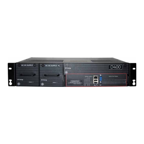
Page 27: First Look At The D400
CHAPTER 2: INSTALLING THE D400 FIRST LOOK AT THE D400 First look at the D400 Front Panel The front panel of the D400 provides easy access to the status indicators, user connections and power supply units. Figure 4: D400 front panel Power... -
Page 28: Physical Installation
The D400 can be installed in a standard 19-inch rack or substation panel. The D400 is supplied with a ½ AA 3.6 V 0.9 Ah Lithium battery that you must insert on the D400 main board when the D400 is installed. -
Page 29: Panel Mount
Cutout for panel mounting Battery installation To insert the Lithium Remove the D400 main module from the chassis and insert the battery in the battery holder BT1. See “Replacing the battery” on page 100 for more information. battery Battery removal J12 - battery backup The D400 card contains a 3.6V lithium battery to maintain NVRAM contents (processor and... - Page 30 PHYSICAL INSTALLATION CHAPTER 2: INSTALLING THE D400 GENERAL D400 SUBSTATION GATEWAY USER’S MANUAL...
-
Page 31: Setting Up Communication Cards
D400 with default settings. Communication cards All communication cards plug into I/O adapter card slots at the rear of the D400 chassis. The communication cards are powered from the backplane of the D400. Figure 7: D400 I/O adapter card slots... -
Page 32: Types Of Communication Cards
D400 unit to remove and install the communication cards. To change the At the rear panel of the D400, using a flathead or Phillips screwdriver loosen (but don't completely remove) the two screws from the top and bottom of the communication settings on a card. -
Page 33: Rs-232 Adapter
The RS-232 Adapter (GE Item No. 520-0207LF) is a standard RS-232 serial I/O adapter card that plugs into any serial communication slot (slots 1 through 8) on the D400. It contains two independently isolated RS-232 serial ports (Port 1 J3 and Port 2 J2) each with a DB-9 connector with common shields. -
Page 34: Switch Sw1/Sw2 Configuration
*Use DTE or DCE settings as appropriate DCD output is not supported in DCE mode. Each +5 V output is independently isolated and fused with a PTC (positive temperature coefficient) resettable fuse at 320 mA at 65 °C. GENERAL D400 SUBSTATION GATEWAY USER’S MANUAL... -
Page 35: Switch Sw3/Sw4 Configuration
DCE (Pin 4 DTR Input from DTE and Pin 6 DSR Output to DTE). See Figure 12. • IRIG-B Enable (on Pin 4) and Ground (on Pin 6). See Figure 13. Figure 11: Switch SW3/SW4 configuration for port DTE (default) D400 SUBSTATION GATEWAY USER’S MANUAL GENERAL... - Page 36 RS-232 ADAPTER CHAPTER 3: SETTING UP COMMUNICATION CARDS Figure 12: Switch SW3/SW4 configuration for port DCE Figure 13: Switch SW3/SW4 configuration for port IRIG-B) GENERAL D400 SUBSTATION GATEWAY USER’S MANUAL...
-
Page 37: Rs-485 Adapter
The RS-485 Adapter (GE Item No. 520-0208LF) plugs into any serial communication slot (slots 1 through 8) on the D400. It contains two independently isolated RS-485 channels on a single terminal block TB1: Channel 1 on terminals TB1-1 through TB1-5 and Channel 2 on terminals TB1-6 through TB1-10. -
Page 38: Switch Sw3/Sw4 Configuration
If RS-422 termination/pull-up is selected, the TX+ and RX+ signals have a 680 ohm pull-up resistor, the TX- and RX- signals have a 680 ohm pull-down resistor, and the RX and TX signals have a 120 ohm termination. GENERAL D400 SUBSTATION GATEWAY USER’S MANUAL... - Page 39 Figure 16: RS-485 Mode - 12 KOhm (Single Unit Load)) Figure 17: RS-422 120 Ohm Line Termination on TX and RX Figure 18: RS-422 120 Ohm Line Termination with 680 Ohm Pull-Up and Pull-Down Resistors D400 SUBSTATION GATEWAY USER’S MANUAL GENERAL...
-
Page 40: Fiber Optic Serial Adapter
Fiber Optic Serial card. Follow instructions for setting the switch to select the appropriate state for each channel. The fiber optic channel settings on the D400 must match the set up of the other end of the fiber optic communications channel. - Page 41 CHAPTER 3: SETTING UP COMMUNICATION CARDS FIBER OPTIC SERIAL ADAPTER Figure 19: Glass Optical Fiber Serial Adapter Figure 20: Plastic Optical Fiber Serial Adapter D400 SUBSTATION GATEWAY USER’S MANUAL GENERAL...
-
Page 42: Irig-B Input Adapter
IRIG-B input adapter The IRIG-B Input Adapter (GE Item No. 520-0211LF) plugs into a dedicated IRIG-B slot (slot 9) on the D400. The IRIG-B Input card accepts an IRIG-B signal in one of three input formats through a corresponding connector type: •... -
Page 43: Switch Sw2 Configuration
CHAPTER 3: SETTING UP COMMUNICATION CARDS IRIG-B INPUT ADAPTER Leave switch SW1 in the Standard position as it is required for the D400 to properly decode and set the system time. Figure 21: IRIG-B Input Adapter Switch SW2 configuration Switch SW2 controls the signal option for the selected state option (SW1). It contains three switch positions that can be set to ON or OFF to select the appropriate signal. -
Page 44: Irig-B Distribution Adapter
CHAPTER 3: SETTING UP COMMUNICATION CARDS IRIG-B distribution adapter The IRIG-B Distribution Adapter (GE Item No. 520-0212LF) is an optional IRIG-B output card to supply a pulse width coded IRIG-B (TTL) signal passed from the IRIG-B Input card to attached devices. The IRIG-B Distribution card provides four channels on a single terminal block. -
Page 45: 4-Port Twisted-Pair Ethernet Switch
A second Ethernet switch can be installed in the NET2 slot (slot 12). If two Ethernet switches are installed in the NET slots, the D400 may be used in a dual-IP redundancy mode. That is, each switch can be configured with a different IP address to provide a backup network connection if the primary channel fails. -
Page 46: 10Base-Fl Hot Standby Fiber Optic Ethernet Switch
D400 switches to the secondary port (Fiber Optic Channel 2) if it has a valid link. The D400 reverts to the primary port if the primary link is restored or no signal is present on the secondary port. The data rate on each port is independently detected and set to 10 Mbps or 100 Mbps. -
Page 47: 100Base-Fx Hot Standby Fiber Optic Ethernet Adapter
D400 switches to the secondary port (Fiber Optic Channel 2) if it has a valid link. The D400 reverts to the primary port if the primary link is restored or no signal is present on the secondary port. The data rate on each port is 100 Mbps. -
Page 48: Com2 Port Adapter
• Wide area network The COM2 Port Adapter plugs into any NET slot (slots 11 and 12) of the D400. The COM2 Port requires an external modem to provide dial-up functionality. See “Modem connections” on page 63 for typical cable connections. -
Page 49: Redundant Twisted-Pair Ethernet + Com2 Port Adapter
104-Plus Ethernet Module. The Ethernet switch can support a dual-redundancy network option on the D400. The data rate on each LAN or WAN port is independently detected and set to either 10 Mbps or 100 Mbps. The card also provides an RS-232 DCE connection through a DB-9 connector. -
Page 50: Usb Kvm And Audio Adapter
CHAPTER 3: SETTING UP COMMUNICATION CARDS USB KVM and audio adapter The USB Keyboard, Video, Mouse Adapter (GE Item No. 520-0206LF) plugs into the USB KVM slot (slot 13) on the D400. The card provides connections for setting up a permanent local workstation, including: •... -
Page 51: Connecting To Devices And Networks
For more information about the types of communication cards and configuration options, see Chapter 3, Setting Up Communication Cards. Serial The D400 can support up to 16 serial connections (up to 8 serial adapter cards with 2 ports each) to a variety of GE and other vendor devices, including: •... -
Page 52: Network
Local substation computer A substation computer can be set up with the D400 through the USB KVM connections to access the local HMI. Optionally, a portable PC can be connected to the front Ethernet port to access the HMI. -
Page 53: General Cabling Requirements
External Power Source Power Supply and System Fail Alarms The types of communication cards included in your D400 depend on what was ordered for your substation application. For a list and detailed description of the types of communication cards available, see Chapter 3, Setting Up Communication Cards. -
Page 54: Connections
DCD output not supported in DCE mode. RS-485 connections The D400 accepts connections to RS-485 2-wire and 4-wire type devices through the RS- 485 Adapter. The RS-485 Adapter (GE Item No. 520-0208LF) plugs into any serial communication slot (slots 1 through 8) on the D400. It contains two independently isolated RS-485 channels on a single terminal block: Channel 1 on terminals TB1-1 through TB1-5 and Channel 2 on terminals TB1-6 through TB1-10. -
Page 55: Cabling Requirements
Figure 31: RS-485 2-wire devices - wiring connection Relay RS485- RS485+ Table 11: RS-485 2-Wire Terminal Block Signal Definitions RS-485 Channel Position Number 2-Wire Function Signal Flow Channel 1 TX1+ IN/OUT TX1− IN/OUT FGND 1 Shield RX1− RX1+ D400 SUBSTATION GATEWAY USER’S MANUAL GENERAL... -
Page 56: 4-Wire Connections
“RS-485 adapter” on page 37). Figure 32: RS-485 4-wire devices - wiring connection Device 1 Device 2 Device 3 RX+ RX- TX+ TX- GND RX+ RX- TX+ TX- GND RX+ RX- TX+ TX- GND GENERAL D400 SUBSTATION GATEWAY USER’S MANUAL... -
Page 57: Fiber Optic Serial Connections
The terminal block positions are numbered from 1 to 10 starting from the bottom of the card. Fiber optic serial connections For devices located some distance from the D400, they may be connected using glass or plastic optical fiber cables. Fiber optic cabling also offers superior performance in electrically noisy environments. -
Page 58: Plastic Optical Fiber
IRIG-B input adapter The IRIG-B Input Adapter (GE Item No. 520-0211LF) plugs into a dedicated IRIG-B slot (slot 9) on the D400. The IRIG-B Input card accepts an IRIG-B signal in one of three input formats through a corresponding connector type: GENERAL D400 SUBSTATION GATEWAY USER’S MANUAL... -
Page 59: Irig-B Distribution Adapter
Each channel is capable of supplying a signal to up to four IEDs, for a total of 16 IEDs. The IRIG-B Distribution card plugs into a dedicated IRIG-B slot (slot 10) on the D400. Terminal blocks accept a range of 24 to 14 AWG [0.2 to 2.1 mm²] Recommended wire strip length is 0.2"... -
Page 60: Hot Standby Fiber Optic Connections
That is, each switch can be configured with a different IP address to provide a back up network connection if the primary channel fails. You can use the following glass optical fiber (GOF) cabling with the D400 Hot Standby Fiber Optic Ethernet Switches: •... -
Page 61: Networks Network
Figure 37: D400 Ethernet ports If the D400 is deployed in the presence of strong RF energy in the 110 MHz to 125 MHz band, such as airport Instrument Landing System (ILS) localizers or aviation radio transmitters, it is recommended that shielded twisted-pair Ethernet cables be used. - Page 62 10 Mbps, full duplex, on your PC. The network interface must be configured before the network ports can be used. See “Connecting to the D400 for the first time” on page 83 for more information. Table 15: Ethernet RJ-45 Connector Signal Definitions...
-
Page 63: Modem Connections
The COM2 port provides a single DB-9 connector wired for an RS-574 DTE signal. The COM2 Port Adapter plugs into any NET slot (slots 11 and 12) of the D400. The Redundant TP Ethernet + COM2 Port Adapter plugs into the NET1 slot (slot 11). -
Page 64: Local Hmi Connection
DB-25 Pin # Local HMI connection A permanent local workstation can be set up with the D400 to access the D400’s Local HMI (human machine interface). The computer peripherals connect to the USB KVM Adapter located on the rear panel of the D400. The D400 supports the following peripheral connections: •... -
Page 65: Front Maintenance Port
The serial communications port on the front panel of the D400 provides a local connection with the D400 to perform the initial setup of the D400 and to carry out maintenance and diagnostic procedures. The front maintenance port provides for a direct serial connection to a PC using a serial null modem cable (GE Item No. -
Page 66: Minimal Required Connection
If the Hot Standby redundancy feature is available, the RS232 switch panel is optional. A pair of LEDs marked CCU A and CCU B indicate which of the D400 units is currently active. If the hardware or software of the active unit fails, it is automatically switched offline and serial connections to the field are transferred to the standby unit. -
Page 67: Required Components
DB9 serial connector to either P1 or P9 as shown below. Connect one end of the ping cable to the first D400 and the other end to the second D400. This ping cable must be connected to the same serial port number on both units. -
Page 68: Rs232 Switch Panel
Connections from the switch panel to both D400 units should be made in the same order. For example, if P2 is connected to port 3 on the first D400, P10 should also be connected to port 3 on the second D400. -
Page 69: Redundancy Wiring Diagrams
The CCU A/CCU B LED indicator indicates which unit has been activated. Redundancy wiring diagrams The following diagrams illustrate how to wire the D400 units and RS232 switch panels to enable system redundancy: • Redundancy Wiring - Single RS232 Switch Panel See “Redundancy Wiring - Single RS232 Switch Panel”... - Page 70 D400 SYSTEM REDUNDANCY CHAPTER 4: CONNECTING TO DEVICES AND NETWORKS Figure 42: Redundancy Wiring - Single RS232 Switch Panel GENERAL D400 SUBSTATION GATEWAY USER’S MANUAL...
- Page 71 CHAPTER 4: CONNECTING TO DEVICES AND NETWORKS D400 SYSTEM REDUNDANCY Figure 43: Redundancy Wiring - Dual RS232 Switch Panel (1 of 2) D400 SUBSTATION GATEWAY USER’S MANUAL GENERAL...
- Page 72 D400 SYSTEM REDUNDANCY CHAPTER 4: CONNECTING TO DEVICES AND NETWORKS Figure 44: Redundancy Wiring - Dual RS232 Switch Panel (2 of 2) GENERAL D400 SUBSTATION GATEWAY USER’S MANUAL...
- Page 73 CHAPTER 4: CONNECTING TO DEVICES AND NETWORKS D400 SYSTEM REDUNDANCY Figure 45: Redundancy Wiring - Redundant RS232 Switch Panel (1 of 2) D400 SUBSTATION GATEWAY USER’S MANUAL GENERAL...
- Page 74 D400 SYSTEM REDUNDANCY CHAPTER 4: CONNECTING TO DEVICES AND NETWORKS Figure 46: Redundancy Wiring - Redundant RS232 Switch Panel (2 of 2) GENERAL D400 SUBSTATION GATEWAY USER’S MANUAL...
-
Page 75: Powering Up The D400
This chapter describes the power supplies and how to make power connections. Power supply options The D400 supports one or two power supplies that provide 5 V to the D400 main module. The following power supplies may be provided in the Power Supply slots: •... -
Page 76: Redundant Power Supply
Redundant power supply The D400 may be provided with an optional redundant power supply unit in Power Supply Slot 2. The second power supply provides continuous power to the D400 in the event the primary power supply unit fails. Additional protection can be provided if a secondary external power source is available. In the event the primary power source fails, an automatic switchover will take place to the redundant power source to ensure continuous power to the D400. -
Page 77: Wiring Requirements
Wiring requirements The supply wiring for the D400 must be a minimum of 18 AWG [0.82 mm²], 3-conductor cable with an external insulation jacket, and a minimum certified voltage rating of 600 V. - Page 78 POWER CONNECTIONS CHAPTER 5: POWERING UP THE D400 To connect the power Remove the terminal block TB1 protective plastic cover. source to the D400 Connect power source as follows: If your power supply is… then… Connect the AC line connection to the L connection point(s) and...
-
Page 79: Power Supply Alarms
It is recommended to terminate 12 AWG green & yellow wire with a Panduit PV10-14R or equivalent ring terminal. Verify that Power LEDs on the front panel of the power supplies and the D400 main module are lit. Replace the terminal block protective plastic cover. -
Page 80: Power Fail Alarm
POWER SUPPLY ALARMS CHAPTER 5: POWERING UP THE D400 Power fail alarm The Power Fail contact closure provides for an external indication upon loss of power. The Power Fail alarm is also indicated by the Power LED on the front panel of the power supply turning off. -
Page 81: System Fail Alarm
POWER SUPPLY ALARMS System fail alarm The D400 includes a System Fail contact closure to provide an external indication of system status. The System Fail alarm is also indicated by the CPU Ready LED on the front panel of the main module turning off. -
Page 82: Powering Down The D400
The D400 is like a computer and the system must be shut down properly before removing the power. For the shut down procedure, see “Shutting down the D400” on page 98. It may take a couple of minutes for the D400 to fully shut down and for the CPU Ready LED to go off. -
Page 83: Setting Up The D400
D400. Connecting to the D400 for the first time To perform the initial set up of the D400, you need to plug directly into the D400 through the front serial communications port. The front communications port provides a local connection and terminal session with the D400 and is used to perform system administrative and maintenance procedures. - Page 84 In the main terminal window, press Enter. Result: The D400 login prompt appears. At the D400 login prompt, type the default username root and press Enter, Type the default password geroot and press Enter. When you type in the password, it does not appear on the screen.
-
Page 85: Setting Up The Network Interface
Subnet Mask • Gateway address (if applicable) This set up must be done the first time from the D400’s front serial communications port. To configure the Connect to the front maintenance port. See “Connecting to the D400 for the first time”... - Page 86 Type 2 and press Enter to select 2. Static IP Address. Result: You are prompted to enter the D400’s IP address. Type the IP address of the D400 and press Enter, or press Enter to accept a previously- set IP address.
-
Page 87: Creating Administrator-Level User Accounts
D400’s front network port. The PC connecting to the front Ethernet port of the D400 must be configured to be on the same network as Net1 (slot 11) and the host ID must be unique to the network. -
Page 88: Installing The Certificate And Key
Once you have installed and set up your security certificate, your secure Web access with the D400 is enabled. From this point on, whenever you access the D400 HMI using a Web browser, the D400 will automatically send you its Web site certificate, and your Web browser will display a lock icon on the status bar. -
Page 89: Testing The Network Connection
Check with your IT administrator on how to proceed. Testing the network connection Once you have finished setting up the D400's network interface, you may want to test the connection to ensure that your computer and the D400 are communicating properly. To test the connection, you can run the ping command at the D400's command line interface. - Page 90 TESTING THE NETWORK CONNECTION CHAPTER 6: SETTING UP THE D400 GENERAL D400 SUBSTATION GATEWAY USER’S MANUAL...
-
Page 91: Using The D400
System Utilities allow you to manage the D400 system setup. Front panel LEDs Once the D400 is powered up, the LED indicators on the front panel of the D400 become active. The indicators provide status information on the operation of the D400. -
Page 92: System Status Leds
Transmission activity for the Ethernet Switch in NET1 and NET2 slots. See note below. The NET2 ACT/LINK LEDs on the front panel may not be properly driven on the D400 Main Module with FPGA revision V1.4 and earlier when using the Redundant TP Ethernet + COM2 Port card (GE Item No. -
Page 93: D400 Hmi
For more information on the D400 HMI, refer to the online Help once you have logged in. The D400, when equipped with a 1.0 GHz CPU, also includes a Local HMI that offers all the features of the D400 HMI through a local connection. A feature-reduced version of the Local HMI is available for D400 units containing a 650 MHz CPU. -
Page 94: Local Hmi
Local HMI The access to the Local HMI is through a keyboard, monitor, and mouse connected to the USB KVM card on the rear panel of the D400. For KVM setup information, see “Local HMI connection” on page 64. The D400’s Local HMI is presented within an X Windows environment running on the Linux operating system. -
Page 95: System Utilities
HyperTerminal, which supports a Telnet session, but does not include an SSH terminal emulator. This must be obtained and installed separately. You cannot use the root user account to access your D400 remotely. You must use an Administrator-level user account (or a Supervisor-level user account, if so configured). -
Page 96: File Transfer
User CompactFlash card is accessible from the front panel and stores system data such as event logs To copy files from the CompactFlash cards you can use an ftp session through the D400’s command line interface or a portable memory device connected to the D400’s front USB port. -
Page 97: System Status Points
CHAPTER 7: USING THE D400 SYSTEM STATUS POINTS System status points You can obtain status information about your D400 through several system points. These points can be viewed through the Application tab on the Point Summary window. Table 23: D400 System Status Points... -
Page 98: Shutting Down The D400
CPU Ready LED on the D400 front panel turns off and the System Fail power supply alarm is set (if wired). You can now safely disconnect the power. It may take a couple of minutes for the D400 to fully shut down and for the CPU Ready LED to go off. -
Page 99: Servicing The D400
Only trained personnel should perform maintenance on the D400. Removing the D400 main module You need to remove the D400 main module from the chassis to access the system battery and the main CompactFlash card for maintenance. Figure 52: D400 Main Module D400 SUBSTATION GATEWAY USER’S MANUAL... -
Page 100: Replacing The Battery
The lithium battery maintains power to the D400's NVRAM if there is a power disconnect. The D400 is supplied with a 1/2AA 3.6 V 0.9 Ah Lithium battery that you must insert on the D400 main board when the D400 is installed. To ensure the battery is good, it is recommended you check the battery voltage before installation and replace the battery every five years. -
Page 101: Supported Battery Types
Removing the battery causes the internal clock to reset and the non-volatile RAM to be erased. Supported battery types The D400 is supplied with a 1/2AA 3.6 V 0.9 Ah Lithium Thionyl Chloride non-rechargeable battery (GE Item No. 980-0038). The following battery types may be used as a replacement. Table 24: Supported Battery Types Manufacturer Mfg. -
Page 102: Cleaning And Handling Lithium Batteries
For more information see www.weeerohsinfo.com. Battery life If the battery is disconnected, or if the D400 is never powered down, the life of the battery should exceed five years. The life of the battery will be severely shortened if the battery is left connected while the D400 is powered down for extended periods or stored. -
Page 103: Installing The 580-2717 Dual Ethernet Card
CHAPTER 8: SERVICING THE D400 DUAL ETHERNET UPGRADE KIT WITH CARD 580-2717 Perform this procedure on an ESD-safe surface to prevent damage to the D400 device and its components. Installing the 580-2717 dual ethernet card To install the Dual Ethernet Upgrade Kit: Power down your D400 device. - Page 104 Figure 57: Dual Ethernet upgrade kit with card 580-2717 - attach Ethernet module card Replace the D400 main module. Power up the D400 and configure the network connections as required using d400cfg. Refer to the D400 Configuration Utility section in the D400 Substation Gateway Software User’s Manual for more information.
-
Page 105: Dual Ethernet Upgrade Kit With Card 580-3410
GE part no. 520-0214LF [NET2 slot] above GE part no. 520-0215LF [NET2 slot] Perform this procedure on an ESD-safe surface to prevent damage to the D400 device and its components. Installing the 580-3410 dual ethernet card The 580-3410 dual ethernet card only works in conjunction with the 1 GHz CPU. - Page 106 DUAL ETHERNET UPGRADE KIT WITH CARD 580-3410 CHAPTER 8: SERVICING THE D400 Plug the provided cable assembly (GE part number 975-0544) into connector LAN1 and LED1 on PC/104 card and connector P3 on the main board. Note the proper orientation of LED1 connector polarity tab (nubbin facing out towards the card edge), and the LAN1 connector polarity tab (nubbin facing in from the card edge.
-
Page 107: Changing The Compactflash
The D400 contains two CompactFlash cards on the main board to store software and data: • Main CompactFlash card located at connector P2 stores system firmware •... - Page 108 CompactFlash card Using a Phillips Screwdriver, remove the screws from the CompactFlash slot cover located on the front panel of the D400 main module. Press the Eject button to eject the CompactFlash card. Insert the new CompactFlash card into the slot.
-
Page 109: Replacing The Power Supply
D400. Wait 10 seconds for stored energy to dissipate. To replace D400 If only a single power supply unit is installed (in Slot 1), power down the D400. If dual power supply units power supplies are installed (in Slot 1 and Slot 2), ensure that the secondary unit is functioning. - Page 110 REPLACING THE POWER SUPPLY CHAPTER 8: SERVICING THE D400 While pressing the power supply module panel right against the chassis frame, hand- tighten the two screws on the front panel. Verify that the Power LED is illuminated on the replaced power supply unit.
- Page 111 D400 Substation Gateway Appendix A: Standards & Protection Standards & Protection This Appendix lists the standards with which the D400 Substation Gateway has been tested for compliance. Compliance standards Compliance standards are listed for the following categories: • Emission standards; see Table 25 •...
- Page 112 Standard Name Description Test Specification IEC 61010-1 Safety requirements for electrical equipment for measurement, control and laboratory use - General requirements IEC 60255-5 Insulation coordination for measuring relays and protection equipment- Requirements and tests GENERAL D400 SUBSTATION GATEWAY USER’S MANUAL...
- Page 113 To comply, the D400 Substation Gateway BIOS Spread Spectrum clock setting must be set to “disable”. This is the factory default. To comply, the D400 Substation Gateway BIOS DRAM clock setting must be set to “HCLK- 33M”. This is the factory default.
- Page 114 COMPLIANCE STANDARDS APPENDIX A: STANDARDS & PROTECTION GENERAL D400 SUBSTATION GATEWAY USER’S MANUAL...
-
Page 115: List Of Acronyms Acronym Definitions
Decibel-milliwatt, unit of measure - an electrical power unit in decibel (dB) Data Carrier Detect Data Communications Equipment Digital Fault Recorders Data Terminal Equipment Electronic Industries Alliance Electromagnetic Capability Electromagnetic Interference EPUP Environmental Protection Use Period ElectroStatic Discharge European Union D400 SUBSTATION GATEWAY USER’S MANUAL GENERAL... - Page 116 Newton-meter, measure of energy Network Time Protocol NVRAM Non-Volatile Random Access Memory Personal Computer Programmable Logic Controllers Plastic Optical Fiber Point-to-point protocol Positive Temperature Coefficient Return Merchandise Authorization RoHS Restriction of Hazardous Substances Remote terminal unit Receive GENERAL D400 SUBSTATION GATEWAY USER’S MANUAL...
- Page 117 Transistor-Transistor Logic Transmit Unified coarse thread Unified fine thread Universal Resource Locator Universal Serial Bus Unshielded Twisted Pair Volt Amps, unit of measure Volts, Alternating Current, unit of measure Volts, Direct Current, unit of measure D400 SUBSTATION GATEWAY USER’S MANUAL GENERAL...
- Page 118 ACRONYM DEFINITIONS APPENDIX B: LIST OF ACRONYMS GENERAL D400 SUBSTATION GATEWAY USER’S MANUAL...
- Page 119 RS-232 adapter switch sw1/sw2 ...........34 replace ..................100, 101 RS-232 adapter switch sw3/sw4 ...........35 types supported ................. 101 RS-485 adapter switch sw1/sw2 ...........37 RS-485 adapter switch sw3/sw4 ...........38 CONFIGURATION OPTIONS 10base-fl hot standby fiber optic ethernet switch ....46 D400 SUBSTATION GATEWAY USER’S MANUAL GENERAL...
- Page 120 IRIG-B CONNECTIONS ................58 IRIG-B DISTRIBUTION ADAPTER ..........44, 59 FACTORY DEFAULT configuration options ................44 fiber optic serial adapter ..............40 IRIG-B INPUT ADAPTER ..............42, 58 IRIG-B input adapter ................42 configuration options ................42 RS-232 adapter ..................33 GENERAL D400 SUBSTATION GATEWAY USER’S MANUAL...
- Page 121 ..............42 alarms ......................79 switch sw2 configuration ..............43 options .......................75 redundant ....................76 replace ....................109 POWERING DOWN THE D400 ............82 PRECAUTIONS LEDS safety ......................13 front panel ....................91 warning symbols ...................14 serial port status ................... 92...
- Page 122 LEDs ..................92 SETTING UP UNPACKING THE D400 ................26 network interface .................85 UPGRADE secure web access ................87 firmware ....................12 SHUTTING DOWN THE D400 .............98 UPGRADE KIT SPECIFICATIONS dual ethernet card 580-2717 ............102 communications ...................20 dual ethernet card 580-3410 ............105 electrical ....................21 USB KVM &...
- Page 123 Changed RS-485 adapter card default setting to 2-wire. 1.30 Jan 27, 2012 R. Rees Edited entire document for GE Digital Energy manual layout and format. Added content for Hot Standby configuration. Feb 17, 2012 R. Rees Added GE part numbers for CompactFlash to the Changing the CompactFlash section.
- Page 124 GENERAL D400 SUBSTATION GATEWAY USER’S MANUAL...