Kenwood NX-800 Service Manual
Uhf digital transceiver
Hide thumbs
Also See for NX-800:
- Service manual (161 pages) ,
- Specifications (2 pages) ,
- Function reference (608 pages)
Table of Contents
Advertisement
Quick Links
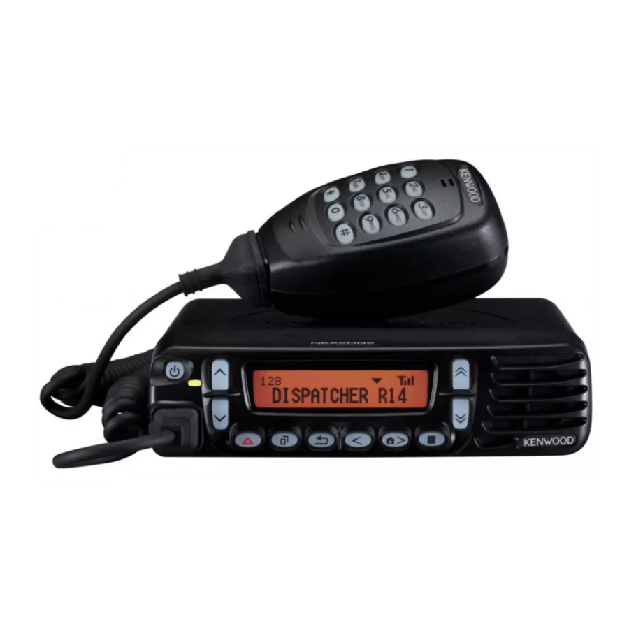
UHF DIGITAL TRANSCEIVER
NX-800
SERVICE MANUAL
General .................................................................. 2
System Set-Up ...................................................... 4
Realignment ......................................................... 5
Installation ......................................................... 8
Disassembly For Repair ................................. 15
Circuit Description .......................................... 18
Components Description .............................. 24
Parts List ............................................................. 27
Exploded View .................................................... 40
Packing ................................................................. 41
Trouble Shooting ............................................ 42
Adjustment ........................................................ 44
Metallic cabinet
(A01-2194-11)
Key top
(K29-9401-03)
Microphone
(T91-0639-35)
CONTENTS
Terminal Function ........................................... 62
PC BOARD
Tx-Rx Unit (X57-7390-10) (B/2) ....................... 71
Tx-Rx Unit (X57-7390-10) (A/2) ....................... 72
Display Unit (X54-3640-10) ............................ 76
Tx-Rx Unit (X57-7390-10) ................................ 78
Display Unit (X54-3640-10) ............................ 93
Interconnection Diagram ............................ 96
Block Diagram ................................................... 98
Level Diagram .................................................. 100
Specifications ................................. BACK COVER
©
2007-12 PRINTED IN JAPAN
B51-8803-00 ( S ) 343
Panel assy
(A62-1162-03)
This product uses Lead Free solder.
Advertisement
Table of Contents

Related Manuals for Kenwood NX-800


Summary of Contents for Kenwood NX-800
- Page 1 UHF DIGITAL TRANSCEIVER NX-800 SERVICE MANUAL © 2007-12 PRINTED IN JAPAN B51-8803-00 ( S ) 343 Metallic cabinet (A01-2194-11) Key top Panel assy (K29-9401-03) (A62-1162-03) Microphone (T91-0639-35) CONTENTS GENERAL ..............2 TERMINAL FUNCTION ........... 62 SYSTEM SET-UP ............4 PC BOARD REALIGNMENT ............
-
Page 2: General
Neither is any liability assumed for damages nicians. resulting from the use of the information contained herein. Kenwood reserves the right to make changes to any products PRE-INSTALLATION CONSIDERATIONS herein at any time for improvement purposes. 1. UNPACKING... - Page 3 5-1. Antenna system Control station. The antenna system selection depends on many factors and is beyond the scope of this manual. Your KENWOOD dealer can help you select an antenna system that will best serve your particular needs. 5-2. Radio location Select a convenient location for your control station radio which is as close as practical to the antenna cable entry point.
-
Page 4: System Set-Up
NX-800 SYSTEM SET-UP Merchandise received License and frequency allocated by FCC Frequency range RF power Type Choose the type of transceiver 450.0~520.0MHz Are you using See page 10. KRK-10 the remote kit? (Option) Are you using See page 8. KCT-46... -
Page 5: Realignment
NX-800 REALIGNMENT 1. Modes 4. Panel Tuning Mode Setting method refer to ADJUSTMENT. User mode 5. PC Mode Panel test mode Panel tuning mode 5-1. Preface The transceiver is programmed by using a personal com- PC mode Data programming mode puter, programming interface (KPG-46/46A) and program- ming software (KPG-111D). -
Page 6: Clone Mode
NX-800 REALIGNMENT 5-3. KPG-46/KPG-46A description 6. Press write button in the window. When the transceiver starts to receive data, the [LOADING] display lights. (PC programming interface cable: Option) 7. If writing ends successfully, the checksum is calculated The KPG-46/46A is required to interface the transceiver to and a result is displayed. - Page 7 NX-800 REALIGNMENT • How to enter the password with the microphone keypad; If you press a key while “CLONE LOCK” is displayed, the number that was pressed is displayed on the transceiver. Each press of the key shifts the display in order to the left.
-
Page 8: Installation
NX-800 INSTALLATION 1. Ignition Sense Cable (KCT-46 : Option) The KCT-46 is an optional cable for enabling the ignition function. The ignition function lets you turn the power to the transceiver on and off with the car ignition key. 1-1. Connecting the KCT-46 cable to the transceiver 1. - Page 9 NX-800 INSTALLATION 2. Horn Alert/P.A. Relay Unit (KAP-2 : Option) The Horn alert (max. 2A drive), Public address and External 5. Place the relay unit at the position shown in Figure 2-2 and speaker function are enabled by installing the KAP-2 in the secure it to the chassis with a screw.
- Page 10 NX-800 INSTALLATION ■ Install the KRK-10 main panel onto the transceiver 3. Control Head Remote Kit (KRK-10 : Option) 4. Insert the flat cable that was removed in step 2 above into The KRK-10 remote kit is used to remotely operate the the connector (CN1) of the interface unit (A/2) of the KRK- transceiver.
- Page 11 NX-800 INSTALLATION ■ Connect the KRK-10 main panel to the rear panel with the cable 10. Install the molded cover ( !3 ) over the connector on the 8. Insert one 14-pin connector of the cable (E30-7514-15) main panel and secure it with two screws ( !4 ).
- Page 12 NX-800 INSTALLATION ■ Connection Procedure 5. External Speaker (Option) Insert the crimp terminal into the Square plug supplied 5-1. KES-3 with the KAP-2. The KES-3 is an external speaker for the 3.5-mm-diameter speaker jack. ■ Connection Procedure 1. Connect the KES-3 to the 3.5-mm-diameter speaker jack on the rear of the transceiver.
- Page 13 NX-800 INSTALLATION 3M Double coated cushion 6. GPS Receiver Connection No. 4016 (or No. 4416) 6-1. Installing the GPS receiver 30 x 25 mm 1. Remove the cabinet, top packing and shielding plate of the transceiver. 2. Remove the front panel from the transceiver.
- Page 14 NX-800 INSTALLATION 6-2. Installing the GPS receiver together with the VGS-1 1. Remove the cabinet, top packing and shielding plate of the transceiver. 2. Remove the front panel from the transceiver. GPS receiver 3. Attach a cushion to the bottom of the VGS-1 as shown in Figure 6-5.
-
Page 15: Disassembly For Repair
NX-800 DISASSEMBLY FOR REPAIR ■ Removing the speaker hardware fixture 1. Precautions on Disassembly (J21-8481-03) and holder (J19-5485-02) ■ TX-RX PCB (TX-RX unit A/2) Disassembly 1. Remove the speaker lead from the holder hook. ( q ) 1. Remove all screws and antenna terminals on the TX-RX 2. - Page 16 NX-800 DISASSEMBLY FOR REPAIR 2. Precautions on Reassembly ■ TX-RX PCB (TX-RX unit A/2) Reassembly 1. With the TX-RX PCB turned over, insert the flat cable from the D-sub PCB (TX-RX unit B/2) into the connector (CN600) on the TX-RX PCB.
- Page 17 NX-800 DISASSEMBLY FOR REPAIR ■ D-sub cap installation procedure To improve water resistance, fit the D-sub cap into the D- sub terminal hardware fixture of the transceiver in the follow- ing order: 1. Fit the left side ( q ) of the D-sub cap into the hardware fixture.
-
Page 18: Circuit Description
CIRCUIT DESCRIPTION 1. Overview 2. Frequency Configuration NX-800 is a UHF Mobile transceiver designed to operate in The receiver is a double-conversion super heterodyne the frequency range of 450 to 520MHz. The unit consists of using first intermediate frequency (IF) of 58.05MHz and sec- receiver, transmitter, phase-locked loop (PLL) frequency syn- ond IF of 450kHz. - Page 19 NX-800 CIRCUIT DESCRIPTION 3-3. IF circuit The second IF signal is passed through the ceramic filter The first IF signal is passed through a four-pole monolithic crystal filter (XF202) to reject adjacent channel signal. The (CF201, CF202) to reject the adjacent channel signal. The filtered first IF signal is amplified by the first IF amplifier filtered second IF signal is amplified by AGC amplifier.
- Page 20 NX-800 CIRCUIT DESCRIPTION 4-2. Base Band Circuit 4. Transmitter System The audio signal output from the base band circuit is con- 4-1. Audio Band Circuit verted to digital data of a sampling frequency of 48 kHz. This The signal from the microphone goes through the mute...
- Page 21 NX-800 CIRCUIT DESCRIPTION 5-3. PLL IC (IC3) 5. PLL Frequency Synthesizer PLL IC compares the differences in phases of the VCO 5-1. VCTCXO (X1) oscillation frequency and the VCTCXO reference frequency, VCTCXO (X1) generates a reference frequency of returns the difference to the VCO CV terminal and realizes 19.2MHz for the PLL frequency synthesizer.
- Page 22 NX-800 CIRCUIT DESCRIPTION 6-4. Key Detection Circuit 6. Control Circuit Keys are detected using Key scan circuit in IC911. The /KI* The control circuit consists of CPU (IC510) and its periph- and KO* signals that are normally pulled up go low when any eral circuits.
- Page 23 The NX-800 contains DSP (IC502) to perform generated by the DSP circuit, superposed on a modulation this operation. The NX-800 compander can be turned on or signal and output from IC510. The modulation balance of the off using the FPU.
-
Page 24: Components Description
NX-800 COMPONENTS DESCRIPTION Display unit (X54-3640-10) TX-RX unit (X57-7390-10) : NX-800 Ref. No. Part Name Description Ref. No. Part Name Description IC901 MOS-IC AFO/BLC SW MOS-IC Temp sensor IC902 MOS-IC AF Buffer AMP (AFO) MOS-IC Buffer AMP (TCXO modulation) IC903... - Page 25 NX-800 COMPONENTS DESCRIPTION Ref. No. Part Name Description Ref. No. Part Name Description IC516 MOS-IC LEVEL SHIFT (RXDO/CTSO) Q402 TRANSISTOR DC SW (SB) IC517 MOS-IC I/O EXPANDER Q403 TRANSISTOR DC SW (IGN) IC518 MOS-IC RS-232C Driver Q404 DC SW (SB)
- Page 26 NX-800 COMPONENTS DESCRIPTION Ref. No. Part Name Description Ref. No. Part Name Description D108~10 DIODE Power Det D903 DIODE Line protection (AUXIO1) D201,202 DIODE CF SW (W/N) D904 DIODE Line protection (AUXIO2) D205 DIODE T/R SW D905,906 ZENER DIODE OVER DC Supply protection...
-
Page 27: Parts List
NX-800 PARTS LIST CAPACITORS CC 45 TH 1H Capacitor value Color* CC45 010 = 1pF 0 = 22pF 100 = 10pF 1 = Type ... ceramic, electrolytic, etc. 4 = Voltage rating Multiplier 2 = Shape ... round, square, ect. - Page 28 E: Europe Les articles non mentionnes dans le Parts No. ne sont pas fournis. Y: AAFES (Europe) X: Australia M: Other Areas Teile ohne Parts No. werden nicht geliefert. NX-800 (Y51-5150-XX) DISPLAY UNIT (X54-3640-10) Ref. No. Address Parts No. Description Destination Ref.
- Page 29 NX-800 PARTS LIST DISPLAY UNIT (X54-3640-10) TX-RX UNIT (X57-7390-11) Ref. No. Address Parts No. Description Destination Ref. No. Address Parts No. Description Destination parts parts J31-0551-05 COLLAR R962 RK73HB1J000J CHIP R J 1/16W R963,964 RK73GB2A391J CHIP R J 1/10W L901,902 L41-1095-39 SMALL FIXED INDUCTOR(1.0UH)
- Page 30 NX-800 PARTS LIST TX-RX UNIT (X57-7390-11) Ref. No. Address Parts No. Description Destination Ref. No. Address Parts No. Description Destination parts parts CC73HCH1H080B CHIP C 8.0PF CC73HCH1H070B CHIP C 7.0PF CK73HB1E103K CHIP C 0.010UF K CK73HB1E103K CHIP C 0.010UF K...
- Page 31 NX-800 PARTS LIST TX-RX UNIT (X57-7390-11) Ref. No. Address Parts No. Description Destination Ref. No. Address Parts No. Description Destination parts parts C207,208 CK73HB1E103K CHIP C 0.010UF K C296,297 CC73HCH1H070B CHIP C 7.0PF C210 CK73HB1A104K CHIP C 0.10UF K C298...
- Page 32 NX-800 PARTS LIST TX-RX UNIT (X57-7390-11) Ref. No. Address Parts No. Description Destination Ref. No. Address Parts No. Description Destination parts parts C441,442 CK73HB1E103K CHIP C 0.010UF K C568-578 CC73HCH1H101J CHIP C 100PF C443,444 CK73GB1E105K CHIP C 1.0UF C579 CK73HB1H102K...
- Page 33 NX-800 PARTS LIST TX-RX UNIT (X57-7390-11) Ref. No. Address Parts No. Description Destination Ref. No. Address Parts No. Description Destination parts parts C757 CC73HCH1H150J CHIP C 15PF CN611,612 E23-1278-05 TERMINAL C761 CK73HB1E103K CHIP C 0.010UF K CN614 E23-1278-05 TERMINAL C762,763...
- Page 34 NX-800 PARTS LIST TX-RX UNIT (X57-7390-11) Ref. No. Address Parts No. Description Destination Ref. No. Address Parts No. Description Destination parts parts RK73HB1J472J CHIP R 4.7K J 1/16W L214 L40-1875-92 SMALL FIXED INDUCTOR(18NH) L215 L39-1498-05 TOROIDAL COIL RK73HB1J474J CHIP R...
- Page 35 NX-800 PARTS LIST TX-RX UNIT (X57-7390-11) Ref. No. Address Parts No. Description Destination Ref. No. Address Parts No. Description Destination parts parts R142 RK73HB1J104J CHIP R 100K J 1/16W R266 RK73HB1J222J CHIP R 2.2K J 1/16W R143 RK73GB2A000J CHIP R...
- Page 36 NX-800 PARTS LIST TX-RX UNIT (X57-7390-11) Ref. No. Address Parts No. Description Destination Ref. No. Address Parts No. Description Destination parts parts R410 RK73HB1J684J CHIP R 680K J 1/16W R544 RK73HB1J104J CHIP R 100K J 1/16W R411 RK73HB1J104J CHIP R...
- Page 37 NX-800 PARTS LIST TX-RX UNIT (X57-7390-11) Ref. No. Address Parts No. Description Destination Ref. No. Address Parts No. Description Destination parts parts R652 RK73HB1J104J CHIP R 100K J 1/16W R755 RK73HB1J103J CHIP R J 1/16W R654 RK73GB2A000J CHIP R J 1/10W...
- Page 38 NX-800 PARTS LIST TX-RX UNIT (X57-7390-11) Ref. No. Address Parts No. Description Destination Ref. No. Address Parts No. Description Destination parts parts R825,826 RK73HB1J103J CHIP R J 1/16W LM73CIMKX-0 MOS-IC R827 RK73HB1J332J CHIP R 3.3K J 1/16W LMC7101BIM5 MOS-IC R828...
- Page 39 NX-800 PARTS LIST TX-RX UNIT (X57-7390-11) Ref. No. Address Parts No. Description Destination Ref. No. Address Parts No. Description Destination parts parts Q101 2SC5108(Y)F TRANSISTOR ∗ Q102 2SC5455-A TRANSISTOR Q105 DTC114EE DIGITAL TRANSISTOR Q106 2SK1830F Q201 DTA114EE DIGITAL TRANSISTOR Q202...
-
Page 40: Exploded View
NX-800 EXPLODED VIEW A :N09-2292-05 B :N67-3008-48 C :N87-2606-43 D :N87-2608-48 IC715 IC403 IC102 TX-RX unit (A/2) (X57-) TX-RX unit (B/2) (X57-) Display unit (X54-) Parts with the exploded numbers larger than 700 are not supplied. If a part reference number is listed in a box on the exploded view of the PCB, that part does not come with the PCB. These parts must be ordered separately. -
Page 41: Packing
NX-800 PACKING 63. MICROPHONE 18. INSTRUCTION MANUAL (T91-0639-35) (B62-2000-00) 30. FUSE(BLADE TYPE)15A/32V (F52-0024-05) 51. MIC HOLDER (J19-1584-15) 45. PACKING FIXTURE (H12-4235-05) 22. DC CORD ASSY (E30-7523-35) 58. BRACKET 61. SCREW SET (J29-0726-03) 46. PACKING FIXTURE (N99-2039-05) (H12-4236-05) 44. INNER CARTON CASE (H02-0630-03) 49. -
Page 42: Trouble Shooting
NX-800 TROUBLE SHOOTING Fault diagnosis of the BGA (Ball Grid Array) IC Overview: A flowchart for determining whether or not the transceiver can be powered on (the LCD does not function even if the power switch is turned on) due to broken BGA parts. - Page 43 NX-800 TROUBLE SHOOTING When a normal value is comfirmed. ● Checking the signal output from the ASIC by software control When an abnormal value is comfirmed. Points to be checked Normal voltage Remove R408. If the ASIC side is 0V, SBC R408 3.3V...
-
Page 44: Adjustment
NX-800 ADJUSTMENT Controls “FNC” not appears Function Display Power switch Volume Up/Down key Channel Up/Down key Microphone key [PTT] Transmit Use as the DTMF keypad. [0] to [9] If a key is pressed during transmission, the DTMF [A] to [D],... - Page 45 NX-800 ADJUSTMENT ■ Frequency and Signaling Panel Tuning Mode The transceiver has been adjusted for the frequencies ■ Preparations for tuning the transceiver shown in the following table. When required, readjust them Before attempting to tune the transceiver, connect the following the adjustment procedure to obtain the frequencies unit to a suitable power supply.
-
Page 46: Key Operation
NX-800 ADJUSTMENT ■ Key operation ■ 5 reference level adjustments frequency Function Tuning point RX (MHz) TX (MHz) Push Hold (1 second) 450.05000 450.10000 [ ] / [ ] Adjustment value up/down Continuation up/down Low’ 467.55000 467.60000 [ ] / [ ]... - Page 47 NX-800 ADJUSTMENT Main LCD Adjust item Order Adjusutment item Sub-LCD display (Analog Wide) (Analog Narrow) (NXDN Narrow) (NXDN Very Narrow) display Number Adjustment range Transmitter QT Deviation 1~1024 Section 8 Transmitter DQT Deviation 1~1024 Section 9 Transmitter LTR Deviation 1~1024...
- Page 48 NX-800 ADJUSTMENT ■ Panel tuning mode flow chart Panel Test Mode ]hold LCD Contrast Adjustment Item N/W/VN CNTR LCD Display ]press [ ]hold For all adjustment items, press the [ ] key to write the adjustment value. 5 reference level...
- Page 49 NX-800 ADJUSTMENT Test Equipment Required for Alignment Test Equipment Major Specifications Standard Signal Generator Frequency Range 400 to 520MHz (SSG) Modulation Frequency modulation and external modulation Output -127dBm/0.1µV to greater than -20dBm/22.4mV * When performing the Frequency adjustment, the following accuracy is necessary.
- Page 50 NX-800 ADJUSTMENT Radio Check Section Condition Measurement Adjustment Item Specifications/ Test- Panel test mode PC test mode Unit Terminal Unit Parts Method equipment Remarks 1. Frequency 1) CH-Sig : 1-1 1) Test Channel f. counter Panel Check an internal 0.3± 0.25ppm...
- Page 51 NX-800 ADJUSTMENT Condition Measurement Adjustment Item Specifications/ Test- Panel test mode PC test mode Unit Terminal Unit Parts Method equipment Remarks 5. Sensitivity 1) CH-Sig : 1-1 1) Test Channel Check 12dB SINAD or Channel : 1 check SSG output...
- Page 52 NX-800 ADJUSTMENT Condition Measurement Adjustment Item Specifications/ Test- Panel tuning mode PC test mode Unit Terminal Unit Parts Method equipment Remarks 5. Frequency * The Frequency 1) Adj item: [PC test mode] [PC test mode] adjust adjustment can be [Frequency]...
- Page 53 NX-800 ADJUSTMENT Condition Measurement Adjustment Item Specifications/ Test- Panel tuning mode PC test mode Unit Terminal Unit Parts Method equipment Remarks ± 1.0W 2. Low Transmit 1) Adj item:[LOLMT] 1) Adj item: Power [Panel 15.0W Power Limit Adjust:[****] [Low Transmit...
- Page 54 NX-800 ADJUSTMENT Condition Measurement Adjustment Item Specifications/ Test- Panel tuning mode PC test mode Unit Terminal Unit Parts Method equipment Remarks ± 50Hz 6. Maximum 1) Adj item:[Nn NDEV] 1) Adj item:[ Maximum 3056Hz Deviation [Panel Deviation Adjust:[****] Deviation(NXDN meter...
- Page 55 NX-800 ADJUSTMENT Condition Measurement Adjustment Item Specifications/ Test- Panel tuning mode PC test mode Unit Terminal Unit Parts Method equipment Remarks 8. QT Deviation 1) Adj item:[An QT] 1) Adj item:[QT Deviation [Panel Write the value as 0.30~0.40kHz adjust *4...
- Page 56 NX-800 ADJUSTMENT Condition Measurement Adjustment Item Specifications/ Test- Panel tuning mode PC test mode Unit Terminal Unit Parts Method equipment Remarks 12.Single Tone 1) Adj item:[An TONE] 1) Adj item:[Single Tone Deviation [Panel Write the value as 1.40~1.60kHz Deviation Adjust:[****]...
- Page 57 NX-800 ADJUSTMENT ■ Mode, Signaling, Necessary adjustment and order Necessary adjustment and order Mode Signaling Wide Narrow Very Narrow Analog Audio 1. Balance adjust 1. Balance adjust 2. Analog Deviation adjust [Wide] 2. Analog Deviation adjust [Narrow] 1. Balance adjust 1.
- Page 58 NX-800 ADJUSTMENT Condition Measurement Adjustment Item Specifications/ Test- Panel tuning mode PC test mode Unit Terminal Unit Parts Method equipment Remarks 3. Sensitivity 2 1) Adj item:[SENS2] 1) Adj item:[Sensitivity 2] [Panel Write the value as Output voltage adjust Adjust:[***] 2) Adj item:[Low] Ext.SP...
- Page 59 NX-800 ADJUSTMENT Condition Measurement Adjustment Item Specifications/ Test- Panel tuning mode PC test mode Unit Terminal Unit Parts Method equipment Remarks 5. Open Squelch 1) Adj item:[An SQL] 1) Adj item:[Open [Panel test mode] adjust *6 Adjust:[***] Squelch (Narrow)] AF VTVM Ext.SP...
- Page 60 NX-800 ADJUSTMENT Condition Measurement Adjustment Item Specifications/ Test- Panel tuning mode PC test mode Unit Terminal Unit Parts Method equipment Remarks 6. Low RSSI at 1) Adj item:[An LRSSI] 1) Adj item:[Low RSSI [Panel test mode] -118dBm Adjust:[***] (Narrow)] Ext.SP...
- Page 61 NX-800 ADJUSTMENT Condition Measurement Adjustment Item Specifications/ Test- Panel tuning mode PC test mode Unit Terminal Unit Parts Method equipment Remarks 7. High RSSI at 1) Adj item:[An HRSSI] 1) Adj item:[High RSSI [Panel test mode] -80dBm Adjust:[***] (Narrow)] Ext.SP...
-
Page 62: Terminal Function
NX-800 TERMINAL FUNCTION Display unit (X54-3640-10) Pin No. Name Function J901 (MIC jack) Pin No. Name Function MIC data detection. CN901 (to TX-RX unit A/2 CN597) HOOK/RXD HOOK:Hook detection, RXD:Serial data input. Speaker input. MIC signal input. Ground. MIC ground. - Page 63 NX-800 TERMINAL FUNCTION Pin No. Name Description Pin No. Name Description SHIFT Control signal output of Beat-shift function CN705 8~11 Ground Power output of switched power supply. /PRST Display CPU reset signal output Speaker output. RX filtered AF signal output Speaker input.
- Page 64 NX-800 TERMINAL FUNCTION Pin No. Name Description J901 (ACC. D-Sub 25pin) RXD1 TXD1 AUXIO9 AUXIO8 TXD2 RXD2 AUXIO7 Refer to AUXIO6 "D-sub 25-pin connector specification". AUXO2 AUXO1 AUXIO5 AUXIO4 AUXIO3 AUXIO2 AUXIO1 Solder Land Name Description to GPS receiver DGND...
- Page 65 NX-800 TERMINAL FUNCTION CN595 26-pin connector specification Rating and Condition Pin No. Pin Name Signal Type Parameter Unit -0.3 OPT1 Digital/CMOS Out/CMOS Inwith Interrupt VOH(Io=-2mA) VOL(Io=2mA) -0.3 OPT3 Digital/CMOS Out/CMOS Inwith Interrupt VOH(Io=-2mA) VOL(Io=2mA) 26P_RD Digital/CMOS Inwith Interrupt -0.3 Baud Rate...
- Page 66 NX-800 TERMINAL FUNCTION Rating and Condition Pin No. Pin Name Signal Type Parameter Unit Input Level Vp-p Analog Coupling Capacitor Input Impedance kΩ -0.3 OPT8 Digital/CMOS Out/CMOS Inwith Interrupt VOH(Io=-2mA) VOL(Io=2mA) -0.3 OPT11 Digital/CMOS Out/CMOS In VOH(Io=-2mA) VOL(Io=2mA) -0.3 OPT7...
- Page 67 NX-800 TERMINAL FUNCTION CN595 26-pin connector specification Pin No. Pin Name Device Connection Description/Function [COR] Conv/LTR L: Not activity receiving H: Activity receiving [TOR] ANI board Aux Input Conv/LTR OPT1 L: Not activity receiving H: Activity receiving [LOK] Conv L: TX Complete...
- Page 68 NX-800 TERMINAL FUNCTION Pin No. Pin Name Device Connection Description/Function ANI board Man-Down Man-Down signal output OPT11 VGS-1 ANI board MIC Mute MIC mute signal input OPT7 VGS-1 ANI board Aux Output Emergency signal input OPT2 VGS-1 ANI board VGS-1...
- Page 69 NX-800 TERMINAL FUNCTION D-sub 25-pin connector specification Rating and Condition Pin No. Pin Name Parameter Unit Input Voltage Range Threshold Low RXD1 Digital Threshold High 1.75 Baud Rate 115200 ± 5 ± 9 Voltage Swing (3kΩ Load) TXD1 Digital Baud Rate 115200 -0.5...
- Page 70 NX-800 TERMINAL FUNCTION Rating and Condition Pin No. Pin Name Parameter Unit The type of this port is open collector. AUXO1 Digital -500 Output Level Vp-p Coupling Capacitor Analog allowable Load kΩ allowable freq 3000 Output Level 0.28 Vp-p Coupling Capacitor allowable Load kΩ...
- Page 71 NX-800 PC BOARD TX-RX UNIT (X57-7390-10) (B/2) Component side view (J79-0130-19 B/2) C905 C906 C904 Component side D906 Layer 1 J79-0130-19 B/2 C903 C915 Layer 2 C902 Layer 3 Layer 4 Ref. No. Address Layer 5 Layer 6 D905 CN901...
-
Page 72: Tx-Rx Unit (X57-7390-10) (A/2)
NX-800 PC BOARD TX-RX UNIT (X57-7390-10) (A/2) Component side view (J79-0130-19 A/2) J701 EXT. SP Q403 R401 CN705 C805 IC715 R826 D408 C820 C132 L106 C131 C128 C123 IC403 L402 R129 L403 R125 D404 C422 C421 F401 C419 C614 C615... - Page 73 NX-800 PC BOARD TX-RX UNIT (X57-7390-10) (A/2) Component side view (J79-0130-19 A/2) Ref. No. Address Ref. No. Address Q201 R152 Q202 Q212 IC102 C190 Q403 Q405 IC101 Q406 C189 IC102 Q411 C177 IC103 Q501 IC201 Q709 C174 IC202 TH102 C194...
- Page 74 NX-800 PC BOARD TX-RX UNIT (X57-7390-10) (A/2) Foil side view (J79-0130-19 A/2) Ref. No. Address Ref. No. Address Ref. No. Address IC204 11F IC401 7M IC402 L115 IC404 IC405 IC408 5M Q101 C179 IC409 Q102 IC410 12J Q203 D110 R151...
- Page 75 NX-800 PC BOARD TX-RX UNIT (X57-7390-10) (A/2) Foil side view (J79-0130-19 A/2) C811 C810 R410 D406 D401 Q401 Q402 C475 R825 L405 C445 C801 C446 Q404 C802 C415 D409 D407 C468 R430 Q414 C443 C804 C454 IC405 Q413 C803 C441...
-
Page 76: Display Unit (X54-3640-10)
NX-800 PC BOARD DISPLAY UNIT (X54-3640-10) Component side view (J79-0157-19) LEFT D929 D914 C922 R922 D935 DM/KVL HK/RXD LEFT DOWN PTT/TXD BLC/AFO DISPLAY UNIT (X54-3640-10) Foil side view (J79-0157-19) CP909 R907 IC905 R963 D904 R952 R935 C927 C948 CP917 IC901... - Page 77 NX-800 PC BOARD DISPLAY UNIT (X54-3640-10) Component side view (J79-0157-19) Ref. No. Address Ref. No. Address R988 R990 Q913 D924 R976 R989 R960 Q913 R991 C958 D908 D925 RIGHT D911 D926 D912 D927 D936 D914 D928 D915 D929 D916 D930...
-
Page 78: Schematic Diagram
NX-800 SCHEMATIC DIAGRAM TX-RX UNIT (X57-7390-10) R : 13.57V T : 13.09V L402 CN401 IC405 L403 LT1616ES6-PBF R : 13.57V T : 13.07V SHDN 5.01V L404 D409 CN402 BooST 1SS388F SURGE REVERSE ABSORPTION PROTECTION L405 22uH IC405,D407,409 DC/DC Converter (50M) - Page 79 NX-800 SCHEMATIC DIAGRAM TX-RX UNIT (X57-7390-10) 4.95V 1.44V 0.92V 2SC5636 BUFFER AMP (PLL FIN) BYPASS DIODE DA221 FC-R : 7.08V RIPPLE FC-T : 6.61V LMC7101BIM5 FILTER OUTPUT 14.34V 13.72V 2SC5383-T111 14.30V INPUT+ INPUT- 470k BUFFER AMP (VCO TUNE) VCO TUNE 3.29V...
- Page 80 NX-800 SCHEMATIC DIAGRAM TX-RX UNIT (X57-7390-10) R : 3.21V T : 0V D3,7,9,10 220n FREQUENCY 0.74V RX VCO CONTROL 150k 150p 0.5p 1SV282-F 2SK508NV(K52) 3.94V 2SC5636 BUFFER AMP (VCO) R : 0V T : 3.47V R153 D4,8,11,12 180n FREQUENCY TX VCO CONTROL 17.5n...
- Page 81 NX-800 SCHEMATIC DIAGRAM TX-RX UNIT (X57-7390-10) BUFFER AMP R : 2.14V R : 0V (RF) T : 4.26V T : 4.94V PRE-DRIVE AMP 1.79V 2SC5636 D101 R158 R160 C101 R103 C104 R106 C105 C109 1000p 100p 100p HVC131 RF DRIVE AMP...
- Page 82 NX-800 SCHEMATIC DIAGRAM TX-RX UNIT (X57-7390-10) IC102 RA30H4452M123 ANTENNA SWITCH L112 L113 L114 D103 1.5T 1.5T 1.5T R126 C186 R152 120p L407CDB R116 R121 R127 C136 470p R : 0V FC-H : 3.77V T : 1.59V FC-L : 3.34V POWER...
- Page 83 NX-800 SCHEMATIC DIAGRAM TX-RX UNIT (X57-7390-10) X2_CLKIN /BER_EN 1.48V 3.31V 15M_1 33M_1 R532 100 MCDIAF R533 0 /MCCSAF DVSS7 R536 0 BCLKX1 MCSCKAF CVSS9 CVSS8 C503 DVDD5 R537 0 0.1u FSDET C518 1u CVDD5 INT3 INT3 INT2 INT1 /DINT INT0...
- Page 84 NX-800 SCHEMATIC DIAGRAM TX-RX UNIT (X57-7390-10) X2_CLKIN X2_CLKIN 3.31V C515 L522 VCC1 VSS1 3.31V DQ11 IC503 L501 SRAM DQ13 IC501 DQ15 FLASH ROM VSS1 VSS2 R504 100k IC504 DELAY RV5C386A 3.31V RESET (CPU) 3.31V IC505 R545 IC506 TC7SH08FU-F 33BU XC6109C29ANN 32KOUT 3.31V...
- Page 85 NX-800 SCHEMATIC DIAGRAM TX-RX UNIT (X57-7390-10) R572 22 X2_CLKIN X2_CLKIN ASQDET R720 R577 100k R569 XTALI XTALo DSPCK /RINT /HINT USRCKI ADD0 ADD1 ADD2 ADD3 ADD4 ADD5 ADD6 ADD7 ADD8 ADD9 ADD10 ADD11 ADD12 ADD13 ADD14 ADD15 ADD16 ADD17 ADD18...
- Page 86 NX-800 SCHEMATIC DIAGRAM TX-RX UNIT (X57-7390-10) X2_CLKIN X2_CLKIN ASQDET R603 3.29V DGND3 DGND2 DGND1 C547 0.1u 33M_4 DVDIo7 C548 0.1u DVDIo6 C549 0.1u DVDIo5 C550 0.1u DVDIo4 C551 0.01u DVDIo3 C552 1u DVDIo2 DVDIo1 C554 0.1u 3.31V DVDD10 C555 0.1u DVDD9 C556 0.1u...
- Page 87 NX-800 SCHEMATIC DIAGRAM TX-RX UNIT (X57-7390-10) X2_CLKIN R915 33M_4 IC511 TC7SH08FU-F 3.31V 3.31V D503 IC508 oUTY 1SS416 SM5023CNDH-G X502 18.432MHz REVERSW C530 CURRENT (PCS RF/HD2) 0.01u PREVENTION oUTPUT (PCS RF) R594 INHN BUFFER AMP (18.432MHz) C531 0.1u BSHIFT L518 33GPS...
- Page 88 NX-800 SCHEMATIC DIAGRAM TX-RX UNIT (X57-7390-10) OPT10 3.28V BUFFER AMP (2nd IF DET) 2nd IF BUFF 3.28V C729 0.1u R : 0V 1.63V T : 1.63V IC706 TC75W51FK(F) MIC AA 1.63V C707 R716 0.1u R725 R722 1.65V R748 R753 C742...
- Page 89 NX-800 SCHEMATIC DIAGRAM TX-RX UNIT (X57-7390-10) OPT10 OPT10 SQ VOLTAGE CONTROL D702 R755 HSC119 R729 100k ASQ DET C722 3.28V NOISE DETECTOR (SQ) D703 R760 RB706F-40 IC705 1.5k BRF/BUFFER TC75W51FK(F) C740 AMP (SQ) 4700p C734 ASQ BPF 0.01 R707 Q702...
- Page 90 NX-800 SCHEMATIC DIAGRAM TX-RX UNIT (X57-7390-10) OPT10 /INAMT SDO0 SCK0 /EVCS C776 1.62V C777 1000p 3.28V 1.62V Q708 2SA1832(GR)F C799 0.1u OPT10 R818 OPT10SEL R836 R821 C789 4.7u C790 10u R822 C813 10u D706 D707 1.62V EMZ6.8N EMZ6.8N LINE LINE...
- Page 91 NX-800 SCHEMATIC DIAGRAM TX-RX UNIT (X57-7390-10) R825 C801 C802 R828 /INAMT R662 470k Q710 R823 DTC363EU R663 470k 4.7k MUTE Q709 /INT25P DTC114EE C591 0.01u LINE PROTECTION (AID9) IC514 TC7WBD125AFK 4.98V I2CCK I2CDT IC517 AIO9 4.98V EXPANDER AIO8 LEVEL SHIFT...
- Page 92 NX-800 SCHEMATIC DIAGRAM TX-RX UNIT (X57-7390-10) IC715 LA4425A 13.54V 1.34V 6.38V CN705 R831 C810 470p D-SUB25 D901 D903 D907 D911 J701 LINE LINE LINE LINE PROTECTION PROTECTION PROTECTION PROTECTION (BER CK) (AUXIO1) (AUXIO3) (AUXIO8) EXT.SP D902 D904 D908 D912 LINE...
- Page 93 NX-800 SCHEMATIC DIAGRAM ● Note : The components marked with a dot ( ) are parts of layer 1. DISPLAY UNIT (X54-3640-10) R924 R925 "PF4" VOL UP R922 CN902 CH UP "PF3" VOL DOWN R923 CH DOWN "PF2" "PF1" TX-RX UNIT (X57-7390-10)
- Page 94 NX-800 SCHEMATIC DIAGRAM DISPLAY UNIT (X54-3640-10) 8.00V 7.97V Q910 12A02CH TX/RX LED 7.27V BACK TX/RX LED (BUSY) LIGHT (TX) R :0V R : 5.00V D915-926 D927-936 Q905 Q906 T : 5.00V T : 0V DTC114EE DTC114EE BACK LIGHT BACK LIGHT...
- Page 95 NX-800 SCHEMATIC DIAGRAM ● Note : The components marked with a dot ( ) are parts of layer 1. DISPLAY UNIT (X54-3640-10) CN905 -4.29V C956 0.01u 33C-2 Q913 C955 UPA672T-A R976 100p FLASH ROM IC913 29AL16D7KCCA 3.30V 3.30V /CS0 R900...
-
Page 96: Interconnection Diagram
NX-800 INTERCONNECTION DIAGRAM CN901 INT SP CN902 SHIFT PRST X54-364*-** DISPLAY UNIT J901 CN905... - Page 97 NX-800 INTERCONNECTION DIAGRAM IC102 RA30H4452M123 26 PIN BOARD TO BOARD CONNECTO R152 CN403 CN705 CN597 HO R GN D EXT SP RX D CN401 SHIFT 13.6 V CN402 CN600 CN901 PRST AUXIO6 AUXIO6 AUXIO7 AUXIO7 AUXIO1 AUXIO1 X57-739*-** AUXIO2 AUXIO2...
-
Page 98: Block Diagram
NX-800 BLOCK DIAGRAM CN401 DCin F401 (13.6V) F53-0328-05 LM73CIMKX-0 DCDC TEMP I2CCK Converter CN402 SENSOR I2CDT IC405 33C 50C XC6204B332P1 3.3V AVR IC402 L77-3016-05 XC6204B332P1 3.3V AVR 1.5V AVR VCTCXO IC408 TCXO_MOD Q416 IC409 BUFF 19.2MHz BUFF XC6204B332M SSM6L05FU XC6205B152PRN... - Page 99 NX-800 BLOCK DIAGRAM 150C 2SC5383-T111 2SC5383-T111 Ripple Ripple FILTER FILTER /T_R T/R SW ASSIST BUFF Q11 SSM6L05FU Q12 2SJ347F LMC7101BIM5 D103 L407CDB D106 PRE- D101,205 L7091CER HVC131 DRIVE DRIVE FINAL LOOP BUFF BUFF FILTER Q5,Q6 2SK508NV(K52) Q101 Q102 IC102 2SC5636...
-
Page 100: Level Diagram
NX-800 LEVEL DIAGRAM Receiver Section Radio Frequency 58.05MHz 450kHz –118dBm –120.5dBm –114.5dBm –112.5dBm –121.5dBm –118.0dBm –104dBm –72.0dBm RF AMP 1st MIX DBM IF AMP IF AMP FM SYSTEM IC D212,D213 D207~D210 XF202 Q210 IC204 Q205 Q204 IC202 Buff AMP Buff AMP... - Page 101 NX-800 LEVEL DIAGRAM Audio Frequency –82.0dBm –82.0dBm 186mVrms 226mVrms 226mVrms 96mVrms 4.00Vrms (EVOL) IF AMP VOL=20 CF203 (ASIC) (RXAF SMF) (RX SUM) (SP AMP) IC201 IC510 IC701 IC711 IC712 IC715 J701 AF VTVM AF level obtained when the AF output level is adjusted for 4.00V/4Ω...
-
Page 102: Specifications
Modulation ..........16K0F3E, 14K4F1D, 11K0F3E, 8K30F1E, 8K10F1E, 8K10F1D, 8K30F1D, 8K30F7W, 4K00F1E, 4K00F1D, 4K00F7W, 4K00F2D Analog measurements made per TIA/EIA 603 KENWOOD reserves the right to change specifications without prior notice or obligation. 2967-3, Ishikawa-machi, Hachioji-shi, Tokyo, 192-8525 Japan P.O. BOX 22745, 2201 East Dominguez Street, Long Beach, Amsterdamseweg 37, 1422 AC Uithoorn, The Netherlands CA 90801-5745, U.S.A. - Page 103 NX-800 PC BOARD TX-RX UNIT (X57-7390-10) (B/2) Component side view (J79-0130-19 B/2) C905 C906 C904 Component side D906 Layer 1 J79-0130-19 B/2 C903 C915 Layer 2 C902 Layer 3 Layer 4 Ref. No. Address Layer 5 Layer 6 D905 CN901...
- Page 104 NX-800 NX-800 PC BOARD PC BOARD TX-RX UNIT (X57-7390-10) (A/2) TX-RX UNIT (X57-7390-10) (A/2) Component side view (J79-0130-19 A/2) Component side view (J79-0130-19 A/2) J701 EXT. SP Q403 R401 Ref. No. Address Ref. No. Address Q201 R152 Q202 CN705 Q212...
- Page 105 NX-800 NX-800 PC BOARD PC BOARD TX-RX UNIT (X57-7390-10) (A/2) TX-RX UNIT (X57-7390-10) (A/2) Foil side view (J79-0130-19 A/2) Foil side view (J79-0130-19 A/2) Ref. No. Address Ref. No. Address Ref. No. Address IC204 11F IC401 7M C811 C810 IC402...
- Page 106 NX-800 NX-800 PC BOARD PC BOARD DISPLAY UNIT (X54-3640-10) Component side view (J79-0157-19) DISPLAY UNIT (X54-3640-10) Component side view (J79-0157-19) Ref. No. Address Ref. No. Address R988 R990 R976 R989 R960 Q913 D924 Q913 R991 C958 D908 D925 LEFT RIGHT...
-
Page 107: Schematic Diagram Tx-Rx Unit (X57-7390-10)
NX-800 SCHEMATIC DIAGRAM Note : The components marked with a dot ( ● ) are parts of layer 1. TX-RX UNIT (X57-7390-10) R : 3.21V BUFFER AMP RA30H4452M123 IC102 X2_CLKIN X2_CLKIN X2_CLKIN X2_CLKIN R572 22 X2_CLKIN X2_CLKIN X2_CLKIN X2_CLKIN R : 13.57V T : 13.09V... - Page 108 NX-800 NX-800 INTERCONNECTION DIAGRAM INTERCONNECTION DIAGRAM IC102 RA30H4452M123 26 PIN BOARD TO BOARD CONNECTO R152 CN403 CN705 CN901 CN597 HO R GN D EXT SP RX D INT SP CN902 CN401 SHIFT SHIFT 13.6 V CN402 CN600 CN901 PRST PRST...
- Page 109 NX-800 NX-800 BLOCK DIAGRAM BLOCK DIAGRAM 150C 2SC5383-T111 2SC5383-T111 Ripple Ripple FILTER FILTER CN401 DCin F401 (13.6V) F53-0328-05 LM73CIMKX-0 /T_R DCDC TEMP I2CCK CN402 Converter SENSOR I2CDT T/R SW ASSIST IC405 BUFF 33C 50C XC6204B332P1 3.3V AVR Q11 SSM6L05FU Q12 2SJ347F...
- Page 110 NX-800 NX-800 LEVEL DIAGRAM LEVEL DIAGRAM Radio Frequency 58.05MHz 450kHz Audio Frequency –118dBm –120.5dBm –114.5dBm –112.5dBm –121.5dBm –118.0dBm –104dBm –72.0dBm –82.0dBm –82.0dBm 186mVrms 226mVrms 226mVrms 96mVrms 4.00Vrms (EVOL) RF AMP 1st MIX DBM IF AMP IF AMP FM SYSTEM IC...