
Related Manuals for Bacharach GDC-150


Summary of Contents for Bacharach GDC-150
- Page 1 Instruction 5209-9000 Operation Manual Rev. 0 - May 2011 Product Leadership • Training • Service • Reliability...
- Page 2 GDC-150 Operation Manual IMPORTANT NOTE READ AND UNDERSTAND THIS MANUAL PRIOR TO USING THIS INSTRUMENT. THIS INSTRUMENT SHOULD BE INSPECTED AND PROGRAMMED BY QUALIFIED AND TRAINED PERSONNEL. THIS INSTRUMENT HAS NOT BEEN DESIGNED TO BE INTRINSICALLY SAFE IN HAZARDOUS OR EXPLOSION-RATED ENVIRONMENTS. FOR YOUR SAFETY, DO NOT USE OR INSTALL IT IN AREAS CLASSIFIED AS HAZARDOUS AREAS (E.G., EXPLOSION-RATED ENVIRONMENTS).
- Page 3 COSTS, TRANSPORTATION COSTS OR CONTINGENT EXPENSES INCURRED WITHOUT PRIOR APPROVAL. BACHARACH, INC. WILL NOT BE HELD LIABLE FOR INDIRECT, INCIDENTAL OR CONSEQUENTIAL LOSS OR DAMAGE OF ANY KIND TO EQUIPMENT CONNECTED, IN ANY WAY, TO THE EQUIPMENT MANUFACTURED BY US.
- Page 4 SHOULD YOUR INSTRUMENT REQUIRE NON-WARRANTY REPAIR, YOU MAY CONTACT THE DISTRIBUTOR FROM WHOM IT WAS PURCHASED OR YOU MAY CONTACT BACHARACH DIRECTLY. IF BACHARACH IS TO DO THE REPAIR WORK, SEND THE INSTRUMENT, PREPAID, TO BACHARACH, INC. AT THE FOLLOWING ADDRESS. BACHARACH, INC.
- Page 5 WEBSITE: www.MyBacharach.com IN NO EVENT WILL BACHARACH, INC., OR ITS OFFICERS OR EMPLOYEES BE LIABLE FOR ANY DIRECT, SPECIAL, INCIDENTAL, OR CONSEQUENTIAL DAMAGES RESULTING FROM ANY DEFECT IN ANY MANUAL, EVEN IF ADVISED OF THE POSSIBILITY OF SUCH DAMAGES.
-
Page 6: Table Of Contents
INSTALLATION ......................8 3.1. Mounting Holes and Conduit Ports ..............8 3.2. Enclosure Door ....................9 3.3. Sensor Mounting Height Recommendations ............10 3.4. Wiring the GDC-150 for Power ................10 OPERATION ......................13 4.1. General ......................13 4.2. Detecting Gas ....................14 4.3. System Failure ....................14 4.4. -
Page 7: Overview
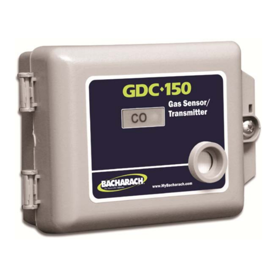
GDC-150 Operation Manual OVERVIEW 1.1. General Description GDC-150 transmitters are rugged, user-friendly, configurable analog transmitter gas detectors for use in non-hazardous (non-explosion rated) environments for commercial HVAC and light industrial use. It can be configured for either electrochemical toxic gas sensors, solid-state sensors, or catalytic sensors. - Page 8 GDC-150 Operation Manual Figure 1-2. Optional Water-Tight (NEMA 4X) Enclosure Figure 1-3. Water-Tight Enclosure (Side View) Showing Optional Splash Guard NOTE: GDC-150 transmitters utilizing catalytic combustible electrochemical H S/SO sensors are supplied with the water- and dust- tight NEMA 4X enclosure standard.
-
Page 9: Key Components
GDC-150 Operation Manual 1.3. Key Components Figure 1-4. Key Components on GDC-150 Circuit Board 5209-9000 Rev 0... -
Page 10: Specifications
GDC-150 Operation Manual SPECIFICATIONS 2.1. General All Sensor Types Power 12 VAC to 30 VAC or 16 VDC to 30 VDC Current 80 to 120 mA One bi-color LED: • Green = Power • Red = Alarm • Flash Green = Warm-up •... -
Page 11: Sensors (Solid-State And Catalytic)
GDC-150 Operation Manual 2.4. Sensors (Solid-State and Catalytic) Solid-State Catalytic Type Solid-state MOS Catalytic pellistor Combustible: 0-50% LEL 0-100% LEL of target Range combustible gas or vapor Refrigerant: 0-2000 ppm Combustible: Approximately 5 to 8 years in clean, ambient conditions... -
Page 12: Sensors (Electrochemical)
GDC-150 Operation Manual 2.5. Sensors (Electrochemical) Life Reso- Response Warm Sensor Range Temp Span lution Time (T -40 TO 0-500 Ammonia (NH +50°C 15-90% <90 sec Carbon Monoxide 0-200 ppm, -20 to 10-95% <2 min 1 hr (CO) +50°C Hydrogen Sulfide... -
Page 13: Sensor Cross Sensitivity (Electrochemical)
GDC-150 Operation Manual 2.6. Sensor Cross Sensitivity (Electrochemical) Sensor Cross Sensitivity – Electrochemical Sensors Only Ammonia 300 ppm CO = 8 10% vol CO = -15 35 ppm NO = 6 0-500 ppm 15 ppm H S = 30 1 ppm Cl... -
Page 14: Installation
The GDC-150 should be installed on a flat vertical surface with the sensor pointing outwards in a clean, dry environment. If the GDC-150 is to be installed in a potentially wet environment, the optional water-tight enclosure should have been selected. This reference refers to the standard, general purpose PVC enclosure. -
Page 15: Enclosure Door
GDC-150 Operation Manual Figure 3-2. Water-Tight Enclosure Showing Mounting Holes WARNING: Do not drill holes in the back of the base of the enclosure for the purpose of mounting the sensor/transmitter. Leak paths can occur. Corrosion damage will not be covered under warranty. -
Page 16: Sensor Mounting Height Recommendations
If powering the GDC-150 with 24 VAC, use terminals 1 and 2. If powering the GDC-150 with 24 VDC, the positive (red) wire should be connected to terminal 2 and the negative (black) wire should be connected to terminal 3. The signal wire is always connected to terminal 4. - Page 17 GDC-150 Operation Manual Figure 3-3. Power and Optional Relay Wiring NOTE: The main wiring terminal strip on the GDC-150 circuit board can be unplugged for easier wiring installation. Grasp the two sides of the terminal strip and lift upward with a slight side to side rocking motion.
- Page 18 GDC-150 Operation Manual Figure 3-4. Proper Wiring Examples 5209-9000 Rev 0...
-
Page 19: Operation
LED will flash green indicating the system is in a warm-up period. During the warm- up period, the signal output from the GDC-150 is fixed at 4.0 mA. If the digital display option has been fitted, the LED display will indicate a scrolling decimal “…..” until the warm-up is completed. -
Page 20: Detecting Gas
GDC-150 Operation Manual 4.2. Detecting Gas Upon detection of the presence of target gas, the signal output increases to a value equal to the amount of gas being detected by the sensor. If the LED display option has been supplied, this value will be displayed. If the concentration of gas is above the preset alarm threshold, the outer LED changes to red, the alarm relay de- energizes and the amber relay coil LED goes out. -
Page 21: Open Loop Diagnostic
4.7. Adjusting the Alarm Set Point (For Relay Option Only) If the optional relay has been supplied, the alarm set point on the GDC-150 can be adjusted. The alarm set point value is converted to a voltage in the range of 0-4 VDC. -
Page 22: Adjusting The Alarm Set Point
Calibration gases. Users can order the calibration kit, calibration accessories and/or gases from any Bacharach authorized distributor or they can supply their own gas and equipment as long as the gas meets the minimum specifications indicated in this manual. 5209-9000 Rev 0... -
Page 23: Calibration Specifications - Gases
The proper calibration adapter should be utilized to allow the gas to properly diffuse around the sensor. They are available from Bacharach (see table on page 21). A humidification chamber must be utilized for all solid-state sensors. This is also available from Bacharach (see table on page 21). -
Page 24: Calculating The Span Gas Value
GDC-150 Operation Manual 5.5. Calculating the Span Gas Value To achieve calibration the user must first tell the GDC-150 what concentration of span he is going to flow over the sensor. Within the transmitter, this is a voltage setting. The range of 0-4 VDC is equal to the full measurement range of the sensor. Prior to attempting to calibrate, determine the voltage value required. -
Page 25: Setting The Span Gas Value
LED will change to a steady amber color. The system now waits 30 seconds to ensure the user is flowing zero air. The GDC-150 then enters a count down during which time it adjusts the null value. The length of this count down period is: •... -
Page 26: Calibrating The Span Value
LED will change to a steady amber color. The system now waits 30 seconds to ensure the user is flowing span gas. The GDC-150 then enters a count down (180 seconds for catalytic and solid-state sensors, 150 seconds for Electrochemical sensors) during which time it adjusts the circuit to the span value which was set earlier (see “Setting the Span Gas Value”). -
Page 27: Accessories And Replacement Parts
GDC-150 Operation Manual ACCESSORIES AND REPLACEMENT PARTS 6.1. Metal Protective Guards GDC-150 series analog transmitters are all supplied very rugged, non-metallic enclosures. However, in some applications more protection may be desired. Bacharach can provide protective guards made from 16 gauge galvanized metal with a pattern of square perforations to permit air and gas to diffuse easily to the sensor. - Page 28 GDC-150 Operation Manual World Headquarters 621 Hunt Valley Circle, New Kensington, Pennsylvania 15068 Phone: 724-334-5000 • Toll Free: 1-800-736-4666 • Fax: 724-334-5001 Website: www.MyBacharach.com • E-mail: help@MyBacharach.com 5209-9000 Rev 0...