Advertisement
Quick Links
TRADELINE
These relays can be used for a variety of switching applications. Typically they provide control of line- or low-voltage
devices by a low voltage controller. See Table 1.
Models
Application
R182J
For 24V thermostat
control of line voltage
devices.
R482J
Controlled by a line
voltage controller
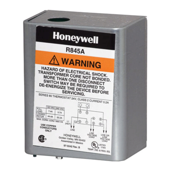
R845A
For hot water zone control
systems or spst control of
two separate loads.
R847A
Provides switching for
high-current loads such as
cooling compressors.
RA89A
For switching one line
voltage load.
RA832A
For switching two line
voltage loads with a
common power source.
a
IMPORTANT: The transformer on the R182 can over-
heat when used with a series 20 thermostat if the
total resistance of the thermostat circuit exceeds
2.5 ohms. If the measured resistance of the thermo-
stat (including thermostat wire and thermostat con-
tact resistance) exceeds 2.5 ohms, add a 100 ohm,
10 watt resistor between the W and R terminals.
Table 2 gives maximum thermostat wire runs; if
longer runs are necessary, measure the resistance or
add a 100 ohm, 10 watt resistor across terminals W
and R.
®
R847A, RA89A, RA832A
TABLE 1—SWITCHING RELAY SPECIFICATIONS.
Voltage
(50/60 Hz)
120
240
120
208/240
120
120
240
120
120
240
J.H. • Rev. 10-94 • ©Honeywell Inc. 1994 • Form Number 69-0791—3
R182J, R482J, R845A,
Switching Relays
Switch
Control
Action
Circuit
Dpdt
3-wire
2-wire
Dpst
Spst
Dpst
TABLE 2—LENGTH OF WIRE.
AWG
Wire
Size
(Number)
22
20
18
16
14
1
Application
Coil
Voltage
Relay Coil
(Vac at
Current
50/60 Hz)
(A)
a
24
0.40
120
0.08
208/240
0.04
24
0.40
Length of Run
Total Wire
to Thermostat
Length
Feet
Meters
Feet
120
38.0
200
61.0
100
300
91.5
150
500
152.5
250
800
244.0
400
Contact
Ratings (A)
AFL ALR
7.4
44.4
3.7
22.2
7.4
44.4
3.7
22.2
7.4
44.4
22
100
10
50
10.2
61.2
7.4
44.4
3.7
22.2
(Wires)
Meters
60
18.0
30.5
45.5
76.0
122.0
69-0791—3
Advertisement

Related Manuals for Honeywell TRADELINE R182J


Summary of Contents for Honeywell TRADELINE R182J
- Page 1 30.5 longer runs are necessary, measure the resistance or add a 100 ohm, 10 watt resistor across terminals W 91.5 45.5 and R. 152.5 76.0 244.0 122.0 J.H. • Rev. 10-94 • ©Honeywell Inc. 1994 • Form Number 69-0791—3 69-0791—3...
- Page 2 Installation Fig. 1—Approximate mounting dimensions in in. [mm]. WHEN INSTALLING THIS PRODUCT… 1. Read these instructions carefully. Failure to follow [108] [29] instructions can damage product or cause a hazardous condition. 2. Check the ratings given in the instructions and on the product to make sure the product is suitable for your [48] application.
- Page 3 Fig. 3—Internal schematic and typical hookup Fig. 6—Internal schematics and typical hookup for RA832A. for R482J. LOW VOLTAGE (CLASS 2) R482J 2-WIRE THERMOSTAT AUXILIARY TO LOW OR MILLIVOLTAGE (POWERPILE) LOAD RA832A CONTROLLER LOAD 1 LOAD 2 (OPTIONAL) N.O. N.C. COM. N.O.
- Page 4 ARE CONNECTED IN PARALLEL. M8231B Home and Building Control Home and Building Control Helping You Control Your World Honeywell Inc. Honeywell Limited—Honeywell Limitée 1985 Douglas Drive North 740 Ellesmere Road Golden Valley, MN 55422 Scarborough, Ontario M1P 2V9 QUALITY IS KEY 69-0791—3...