Advertisement
Quick Links
Honeywell
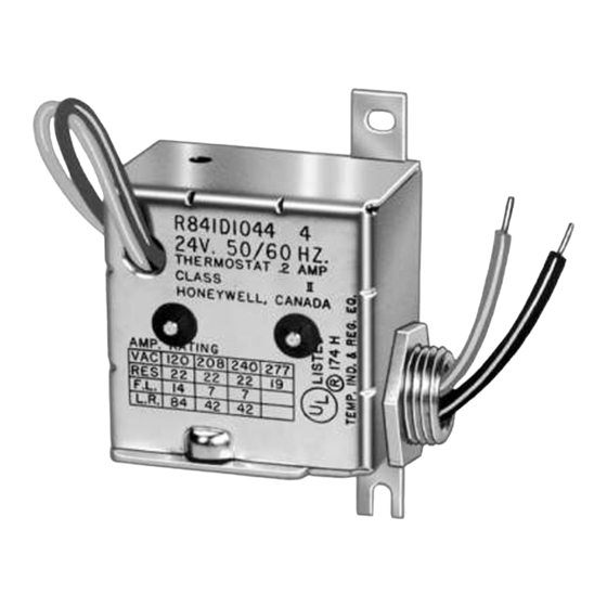
THE R841 ELECTRIC HEATING RELAY IS
USED WITH A 2-WIRE, 24V THERMOSTAT
TO PROVIDE CONTROL OF ELECTRIC
HEATING EQUIPMENT. IT IS A DIRECT-
FOLLOWING RELAY WHICH OPERATES
WITH EACH CYCLE OF THE THERMO-
STAT (4 TO 6 CYCLES PER HOUR).
load.
to control two loads simultaneously, or with
two thermostats to control two independent
loads.
transformer; R841 D model must be powered
from a remote 24V transformer.
conduit bushing.
The R841C ,D and E models are for instal-
lation on a wireway or J-box.
R841 E has a 1/2 inch male conduit bushing
and includes an enclosure with a low voltage
wiring compartment.
Special R841E with 10 second minimum
timing between stages is available.
Each relay switches up to a 5,000 watt load.
Spst MICRO SWITCH snap switches are
actuated by ambient-compensated bimetal
strips.
Leadwires are provided for both line voltage
and low voltage connections.
Small size and silent operation allow instal-
lation in living area, utility room, or basement,
May be mounted in any convenient position.
REV. 10-79 (.11)
Advertisement

Summary of Contents for Honeywell R841C-E
- Page 1 Honeywell THE R841 ELECTRIC HEATING RELAY IS USED WITH A 2-WIRE, 24V THERMOSTAT TO PROVIDE CONTROL OF ELECTRIC HEATING EQUIPMENT. IT IS A DIRECT- FOLLOWING RELAY WHICH OPERATES WITH EACH CYCLE OF THE THERMO- STAT (4 TO 6 CYCLES PER HOUR).
-
Page 2: Tradeline Models
OFFiCE (CHECK WHITE PAGES PHONE DIREcToRY). YOUR LOCAL SALES 2. RESIDENTIAL DIVISION CUSTOMER SERVICE HONEYWELL INC., 1885 DOUGLAS DRIVE NORTH Ml NNEAPOLIS, MINNESOTA 55422 (612) 542-7500 CONTROLS LIMITED, (IN CANADA–HONEYWELL 740 ELLESMERE ROAD, SCARBOROUGH, ONTARIO MIP 2V9) INTERNATIONAL SALES AND SERVICE OFFICES IN ALL PRINCIPAL CITIES OF THE WORLD. -
Page 3: Optional Specifications
7/8 in. [22. 2 mm] knockouts in back and sides of LEADWIRE LENGTH (NOMINAL): R841C,D– case for 1/2 in. [ 12.7 mm] conduit. DIMENSIONS: See Figs. 1 and 2. Line voltage–18 in. [457.2 mm]. Low voltage–7-l/2 in. [ 190.5 mm]. R841E–... - Page 4 WHEN INSTALLING THIS PRODUCT . . . 1. Read these instructions carefully. Failure to follow them could damage the product or cause a hazardous condition. 2. Check the ratings given in the instructions and on the product to make sure the product is suitable for your application.
- Page 5 T R A N S F O R M E R Ll (HOT) L2 WIRE R841C THERMOSTAT W, F I . BLUE R841D RELAV LOW VOLTAGE \l l T H E R M O S T A T ELEcTRIc BLACK A T E R WHITE NO.
- Page 6 2.WIRE 2-WIRE 24 V 24 V THERMOSTAT THERMOSTAT NO 1 NO. 2 WIRE 24 V THERM05TA7 I !iJ-L$L — ~6R120V %R120V (L3 FOR 208, 240, OR 277 V] (L3 FOR 208,240, OR 2?7 V) MEAN5ANDOVERLOACI DISCONNECT PowERs”PPLY.ADcl ,,0,., TION AS REQUIRED OVERLOAD POWER SUPPLY.
- Page 7 Dear Customer, Honaywell Inc. We welcome your comments and suggestions for improving this publi- Honeywell Plaza cation. Your assistance is greatly appreciated and will eneble us to provide Minneapolis, Minnesota 55408 better tachnical information for ye”. ATTN: Publications Supervisor MN 12-3247 H O N E Y W E L L M I N N E A P O L I S , M N 5 5 4 0 S I N T E R N A T I O N A L Salas Offices in all principal cltias of tha world.


