Hitachi C 10FL Instruction Manual
Stationary table saw
Hide thumbs
Also See for C 10FL:
- Instruction manual (32 pages) ,
- Instruction manual and safety instructions (80 pages) ,
- Instruction manual and safety instructions (32 pages)
Table of Contents
Advertisement
C 10FL
Model
Stationary Table Saw
INSTRUCTION MANUAL AND SAFETY INSTRUCTIONS
WARNING
Improper and unsafe use of this power tool can result in death or serious bodily injury!
This manual contains important information about product safety. Please read and understand
this manual before operating the power tool. Please keep this manual available for others before
they use the power tool.
Advertisement
Table of Contents

Related Manuals for Hitachi C 10FL


Summary of Contents for Hitachi C 10FL
- Page 1 C 10FL Model Stationary Table Saw INSTRUCTION MANUAL AND SAFETY INSTRUCTIONS WARNING Improper and unsafe use of this power tool can result in death or serious bodily injury! This manual contains important information about product safety. Please read and understand this manual before operating the power tool.
-
Page 2: Table Of Contents
Carton Contents ..............8 Push Stick Pattern ..............26 Parts List ................28 HITACHI AUTHORIZED SERVICE CENTERS Service under this warranty is available from Hitachi Koki U.S.A., Ltd. at : IN THE U.S.A. IN CANADA 6395 Kestrel Road Mississauga ON L5T 1Z5 3950 Steve Reynolds Blvd. -
Page 3: Product Specifications
WARNING Some dust created by power sanding, sawing, grinding, drilling and other construction activities contains chemicals known to the state of California to cause cancer, birth defects or other reproductive harm. Some examples of these chemicals are: • Lead from lead-based paints •... -
Page 4: Power Tool Safety
POWER TOOL SAFETY WARNING Before using your table saw, it is critical that you read and understand these safety rules. Failure to follow these rules could result in serious injury or damage to the table saw. Good safety practices are a combination of common 15. -
Page 5: Table Saw Safety
TABLE SAW SAFETY ALWAYS USE SAW BLADE GUARD, splitter and anti- 12. PROVIDE ADEQUATE SUPPORT to the rear and the kickback pawls for every operation for which they can sides of the saw table for long or wide workpieces. be used, including through sawing. Through sawing operations are those in which the blade cuts 13. -
Page 6: Electrical Requirements And Safety
ELECTRICAL REQUIREMENTS AND SAFETY POWER SUPPLY REQUIREMENTS GROUNDING INSTRUCTIONS IN THE EVENT OF A MALFUNCTION OR BREAKDOWN, WARNING grounding provides a path of least resistance for electric current and reduces the risk of electric shock. This saw is equipped with an electric cord that has an equipment To avoid electrical hazards, fire hazards or damage to the grounding conductor and a grounding plug. -
Page 7: Accessories And Attachments
ACCESSORIES AND ATTACHMENTS RECOMMENDED ACCESSORIES WARNING WARNING Visit your Hardware Department or see the Power and To avoid the risk of personal injury: Hand Tools Catalog to purchase recommended Do not use a dado with a diameter larger than 8 ". accessories for this power tool. -
Page 8: Carton Contents
CARTON CONTENTS UNPACKING AND CHECKING CONTENTS WARNING WARNING If any part is missing or damaged, do not attempt to Separate all parts from packing materials. Check each part assemble the table saw, plug in the power cord, or turn with the illustration on the next page and the “Table of Loose Parts”... - Page 9 UNPACKING YOUR STATIONARY TABLE SAW — —...
-
Page 10: Know Your Stationary Table Saw
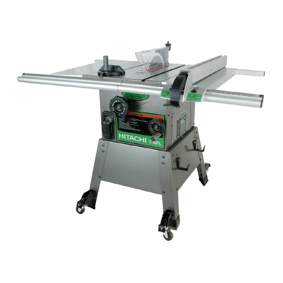
KNOW YOUR STATIONARY TABLE SAW Blade Guard Rip Fence Blade Tilt Scale Miter Gauge Table Extension Table Extension (Left) (Right) Blade Tilting Blade Elevation Handwheel Handwheel ON/OFF Switch with key Leg Stand Castar Table Insert Splitter Table Miter Gauge Storage Rip Fence Storage —... -
Page 11: Glossary Of Terms
GLOSSARY OF TERMS CROSSCUT - A cut made across the width of the HITACHI PROFESSIONAL workpiece. TABLE SAW TERMS FREEHAND - Performing a cut without using a fence MITER GAUGE - A guide used for crosscutting operations (guide), hold down or other proper device to prevent the that slides in the tabletop channels located on either side workpiece from twisting during the cutting operation. -
Page 12: Assembly And Adjustments
ASSEMBLY AND ADJUSTMENTS ESTIMATED ASSEMBLY TIME 50~70 MINUTES (2 PEOPLE) ASSEMBLE STAND (Fig. A) ASSEMBLE TABLE SAW TO STAND (Fig. A, B) Unpack all parts and group by type and size (Fig. A). Place protective corrugated cardboard or old blanket Refer to parts list for quantities. - Page 13 ASSEMBLY THE TABLE EXTENSION (Fig. C) Assembly the rear table rail (Fig. E) Place the left table extension next to the saw table, Attach the side covers (1) and middle plug (2) to the aligning the mounting holes (1). rear table rails (3). Place bolts (2) and thread in mounting holes.
- Page 14 Installing the blade guard assembly (Fig. G) ALIGNING THE BLADE GUARD SPLITTER (Fig. H) 1. Remove the table insert. WARNING 2. Unlock the blade bevel lock knob (1). With the blade evevation handwheel (2), raise the blade to the maximum height. To avoid injury from an accidental start, make sure the 4.
- Page 15 REMOVING THE BLADE (Fig. I) 6. Place the wrench on the arbor nut and turn clockwise (toward the rear of the saw table). WARNING 7. Replace the table insert and blade guard assembly. Verify that the blade and blade guard splitter are aligned.
- Page 16 45 Stop (Fig.K-1) BLADE PARALLEL TO THE MITER GAUGE GROOVE (Fig. M) To avoid injury from an accidental start, make sure the switch is in the OFF position and the plug is disconnected 1. Turn the blade tilting handwheel until the blade tilting from the power source outlet.
- Page 17 INSTALLING THE TABLE INSERT (Fig. N) Power Cord (Fig. P) The table insert has been previously installed on your For convenience and to prevent damage to the power unit. However, you must verify that the table insert is cord when the table saw is not in use or is being flush with the table top surface on all four corners of the transported, the frame of leg has two brackets (1) on the insert.
- Page 18 RIP FENCE ADJUSTMENT (Fig. R) RIP FENCE INDICATOR (Fig. T) For adjustments, position the fence to the right of the NOTE: The rip fence indicator points to the scale on the blade, parallel with the miter gauge groove. front of the table saw. Measurement shown by the Place the rear clamp (1) of the fence on the back rail of indicator will provide the user with accuracy up to 1/16 of the table, and lower the front end over the front rail...
-
Page 19: Operation
OPERATION BASIC SAW OPERATIONS Fig. V RAISE THE BLADE (Fig. U) To raise or lower the blade, turn the blade elevation handwheel (1) to the desired blade height, and then tighten the bevel lock handle (2) to maintain the desired blade angle. - Page 20 RIPPING (Fig. W, X) WARNING Keep your thumbs off the table top. When both of your thumbs touch the front edge of the table (2), finish the cut with a push stick. To make an additional To prevent serious injury: push stick, use the pattern on page 26.
- Page 21 CROSSCUTTING (Fig. Y) BEVEL CROSSCUTTING (Fig. AA) To prevent serious injury: This cutting operation is the same as crosscutting except Do not allow familiarity or frequent use of your table the blade is at bevel angle other than 0 . saw to cause careless mistakes.
- Page 22 USING WOOD FACING ON THE RIP FENCE (Fig. DD) Attach auxiliary fence to rip fence with two "C" clamps. When performing some special cutting operations, add a (Fig. FF) wood facing (1) to the side of the rip fence between the Fig.
-
Page 23: Maintenance
4. A worn, cut, or damaged power cord should be replaced immediately. All electrical or mechanical repairs should be attempted only by a trained repair technician. Contact Hitachi Authorized Service Center for service. Use only identical replacement parts. Any other parts may create a hazard. - Page 24 115V & 230V Wire Wirding Motor (Terminal Block) (BLACK) (Rocker Switch) (BLACK) (BLACK) (BLACK) 230V A(1) 60HZ power B(2) A(1) (BLACK) C(3) (BLACK) C(3) B(2) (BLACK) 230V Wire Wirding Green (Motor) (CIRCUIT (GROUND) BREAKER SWITCH) (WHITE) (BLACK) Motor (WHITE) (Terminal Block) (BLACK) Black (Rocker Switch)
-
Page 25: Troubleshooting Guide
To avoid injury from an accidental start, turn the switch OFF and always remove the plug from the power source before making any adjustments. Consult Hitachi Authorized Service Center if for any reason the motor will not run. SYMPTOM POSSIBLE CAUSES... -
Page 26: Push Stick Pattern
— 26 —... - Page 27 — 27 —...
-
Page 28: Parts List
PARTS LIST 10" STATIONARY TABLE SAW MODEL NO. C10FL Always order by I.D. Number PARTS LIST FOR SCHEMATIC A I.D. Description Size I.D. Description Size I.D. Description Size 1550 CR. RE.COUNT HD. TAPPING SCREW M4*16-16 0KC8 CR. RE. TRUSS HD. TAPPING SCREW M4*16-16 238S POINTER... - Page 29 10" STATONARY TABLE SAW MODEL NO. C10FL SCHEMATIC A 29E2 — 29 —...
- Page 30 10" STATONARY TABLE SAW MODEL NO. C10FL PARTS LIST FOR SCHEMATIC B I.D. Description Size I.D. Description Size 2494 CAU T ION LAB E L 22V1 B R ACK E T 0CS E POW E R COR D CLAM P 22V2 B OT T OM S U PPOR T B R ACK E T 0J 9C...
- Page 31 10" STATONARY TABLE SAW MODEL NO. C10FL SCHEMATIC B — —...
- Page 32 Issued by Hitachi Koki Co., Ltd. Shinagawa Intercity Tower A, 15-1, Konan 2-chome, Minato-ku, Tokyo 108-6020, Japan Distributed by Hitachi Koki U.S.A., Ltd. 3950 Steve Reynolds Blvd. Norcross, GA 30093 Hitachi Koki Canada Co. 6395 Kestrel Road Mississauga ON L5T 1Z5 Code No.