Table of Contents
Advertisement
Available languages
Available languages
Advertisement
Table of Contents

Related Manuals for Craftsman 320.48251


Summary of Contents for Craftsman 320.48251
- Page 1 Owner's Manua Model No. 320.48251 Z___.w CAUTION: Read, understand , SAFETY follow all Safety Rules and Operating • OPERATION Instructions in this manual before using ° MAINTENANCE this product. "ESPAI_IOL, PAGINA 17 Sears, Roebuck and Co., Hoffman Estates, IL 60179 U.S.A.
- Page 2 TroubleShooting ..........Page Service Numbers ..........Back Cover FULL ONE YEAR WARRANTY ON CRAFTSMAN LASER LEVEL If this CRAFTSMAN Laser Level fails to give complete satisfaction within one year from the date of purchase, RETURN IT TO THE NEAREST SEARS...
- Page 3 manual WARNING: before using this level. Failure to follow all instructions may result in BE SURE to read and understand all instructions in this hazardous radiation exposure, electric shook, fire, and/or bodily injury. IIIII I: .... CAUTION: Use of controls or adjustments or performance procedures...
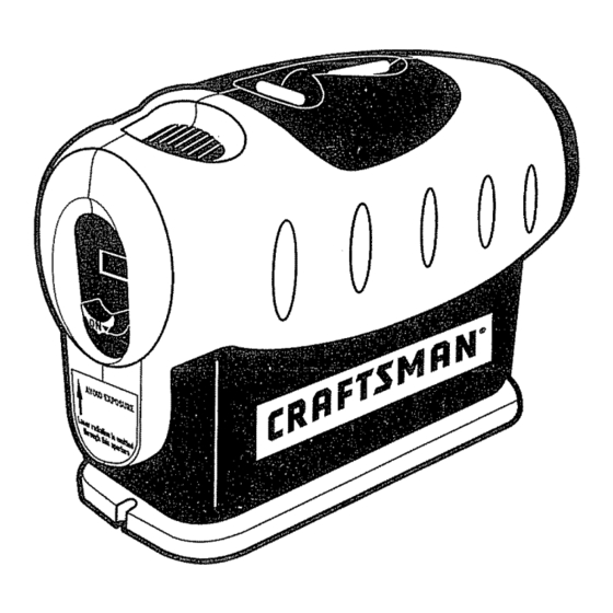
- Page 4 KNOWYOUR LEVEL (See Fig. 1) This Craftsman Laser Trac Level is a highly versatile tool. tt can be hand-held, wall-mounted or leveled on a horizontal surface or tripod stand_ it projects a laser line that sweeps a full 90 °, horizontal to vertical and all angles in between.
- Page 5 TO INSTALL BATTERIES (See Figures 2 and 3) This Laser Trac Level uses two "AA" batteries, check to be sure that IMPORTANT: BEFORE installing the batteries, ALWAYS the on/off switch on the level is in the up off position (see Fig. 2)° Fig.
- Page 6 ADJUSTING THE LASER LINE PROJECTION (See Figure 5) The laser line projected from this tool can be adjusted 90 ° Fig. 5 from vertical to horizontal all angles in between, Use the black finger knob on the top of the tool to adjust angle, 1.
- Page 7 WORKINGWITH OBSTRUCTIONS AND USER INTERFERENCE (See Figures 8 and 9) Figure 8 illustrates the nature of the laser line projected from the Laser Trac Level° It is actually a "plane" of laser light. This is important because obstructions and user interference that takes place in front of the device WILL NOT affect the laser line projected on either side of the user or obstruction.
- Page 8 USING THE LASER TRAC LEVEL This level can be easily and conveniently used in several ways, it can be hand-held, wall-mounted with the pin base or placed in the precision leveling base_ Also use tripod base (included) to mount level to a tripod (not included)_ USING AS A HAND-HELD LEVEL (See Figures 12 and 13) This level can be held in one hand for use as a straight line reference tool...
- Page 9 USING THE LASER TRAC LEVEL (cont.) USING AS A WALL-MOUNTED LEVEL (See Figures 14 to 17) This level can also be wall-mounted using the special base included. Figures 14 and 15 show the top and bottom views of the Thin-Pin Wall-Mount Base°...
- Page 10 USINGTHE LASER TRAC LEVEL (cont.) MOUNTING LEVEL TO THIN-PIN WALL MOUNT BASE (cont.) WARNING: DO NOT push the red buttons on the Thin-Pin Wall Mount Base unless you plan to affix the base to a soft wood or wallboard surface. This could result in injury, because the pins under the base are very sharp instruments, ALWAYS HANDLE THIS BASE PLATE CAREFULLY.
- Page 11 USING THE LASER TRAC LEVEL (cont.) Fig. 18 Fig, 19/_ ve.icaJ Horizontat_ Adjustment Knobs Adjustment Knobs USING LEVEL WITH TRIPOD MOUNTING BASE (see Figure 20) This level can also be used with the Tripod Mounting Base that securely mounts level to any tripod (not included)° This provides even more flexibility in the set up and use of the laser level.
- Page 12 PROJECTING LEVEL VERTICAL LASER LINES (see Figures 2! and 22) When used with the Precision Leveling Base the Laser Trac Level will project a plumb vertical line on the surface directly in front of the tool from any angle in the room (see Figure 21).
- Page 13 This level has been designed to be a tow-maintenancetool However, in order to maintain its performance, you must ALWAYS- f ollow these simple directions. 1. ALWAYShandle the tool with care°Treat it as you would any optical device, such as a camera or binoculars_ 2.
- Page 14 SOLUTION PROBLEM CAUSE Laser line Batteries Replace with fresh batteries are weak_ projection is weak_ Laser line Use laser enhancing glasses. Light in area is hard to is too bright seer Laser line Power switch Check to be sure the power switch cover is in the full is not is not "on".
- Page 15 NOTES...
- Page 16 NOTES...
- Page 17 iVlanual del Usuario IVEL 4 en 1 con Laser Tr'aC M" Modelo No. 320.48251 /_ ATENCION: Antes de usar este producto, lea, comprenda ° SEGURIDAD y siga todas las reqlas de • FUNCIONAMIENTO seguridad y las ms-trucciones o rvlANTENIMIENTO de funcionamiento incluidas en este manual.
- Page 18 Soluci6n de Aver[as ......... PAgina NQmeros de Servicio ........Contraportada GARANTIA COMPLETA DE UN AI_O DEL NIVEL LASER CRAFTSMAN Si este nivel I&ser CRAFTSMAN no te otorga completa satisfacci6n dentro de un a5o de ta fecha de compra, DEVUELVALO ALMACEN SEARS...
- Page 19 ADVERTENClA: ASEGURESE de leer y comprender todas las instrucciones de seguridad indicadas en este manual,, El incumplimiento todas las instrucciones indicadas a continuaci6n puede resultar en exposiciSn peligrosa a radiaci6n, choque el6ctrico, incendio yio lesi6n personal. ATENCiON: Et uso de controles o ajustes o la ejecuci6n procedimientos no especificados...
- Page 20 CONOZCA SU NiVEL (Ver Fig. 1) Este nivel Laser Trac MRCraftsman es una herramienta muy vers&til. Puede sostenerse en la mano, montarse en la pared, colocarse en una superficie horizontal o montar en un trJpode. Proyecta una linea t&ser que recorre 90 ° completos desde la posici6n horizontal...
- Page 21 INSTALACION DE LAS PILAS (Ver Figuras 2 y 3) Este nivel Laser Trac MRusa dos pitas "AA". IMPORTANTE: ANTES de instalar las pilas, SlEMPRE compruebe si el interruptor 'on/off' (encendido/apagado) est#. en posiciSn hacia arriba (apagado) (ver Fig. 2)_ Fig. 2 Fig.
- Page 22 AJUSTE DE LA PROYECCION DE LA LINEA LASER (Ver Figura 5) La linea I&ser proyectada desde esta herramienta Fig. 5 puede ser ajustada 90 ° desde ta posici6n vertical a la horizontal yen todos los &ngulos intermedios, Use el bot6n corredizo negro situado en la parte superior de la herramienta...
- Page 23 TRABAJANDO CON OBSTRUCCIONES E INTERFERENCIA DEL USUARIO (Ver Figuras 8 y 9) La Figura 8 ilustra la naturaleza de ta linea laser proyectada desde el nivel Trac MR.Es en realidad un "plano" de luz laser. Esto es importante porque las obstrucciones e interferencias del usuado que ocurran en frente del dispositivo...
- Page 24 USO DEL NIVEL LASER TRAC M" Este nivel puede ser f&cil y convenientemente usado de varias manera& Puede ser usado en la mano, rnontado en la pared con la base provista de clavijas delgadas o colocado en la base de nivelaci6n a precisi6n, Adem_ts use ta base para tripode (incluida) para instalar el nivel en un tfipode (no incluido)o...
- Page 25 USO DEL NIVEL LASERTRAC MRcont. USO COMO UN NiVEL MURAL (Ver Figuras 14 a 17) Este nivel tambi_n puede usarse montado en la pared usando la base especial que se incluye. Las Figuras 14 y 15 muestran una vista superior e inferior de la Base de Montaje Mural con Clavijas Delgadas.
- Page 26 USO DEL NIVEL LASER TRAC MR cont. MONTAJE DEL NIVEL EN LA BASE DE MONTAJE MURAL CON CLAVlJAS DELGADAS cont. ADVERTENCIA' NO oprima los botones rojos situados en la Base de Montaje Mural con Clavijas Delgadas a menos que usted planee instalar la base en una superficie de madera blanda o fibra prensada_ De io contrario, esto podria causar una lesiSn pues las clavijas de la base son muy afiladas.
- Page 27 USO DEL NIVEL LASER TRAC MRcont. Fig. 18 Perillasde Ajuste Perillasde Ajuste Nineamiento USO DEL NIVEL CON LA BASE DE MONTAJE EN TRIPODE (ver Figura 20) Este nivel tambi6n puede ser usado con la Base de Montaje en Tdpode que permite la instalaci6n del nivet en un tripode (no inctuido), Esto proporciona m&s flexibitidad en el ajuste y uso del nivel l&ser.
- Page 28 PROYECCION DE LINEAS LASER DE NIVELVERTICALES (ver Figuras 21 y 22) Cuando se utiliza con la Base de Nivetaci6n a Precisi6n, el nivel Laser Trac MR proyectar__ una I[nea de nivel vertical a plomo en ta superficie directamente frente de la herramienta desde cualquier...
- Page 29 Este nivel ha sido disefiado como una herramientade bajo mantenimiento. Sin embargo, para mantener su rendimiento,es necesarioque siga SIEMPRE estas sencillas instrucciones. I. SlEMPRE manipule con cuidado la herramienta.Tr&telaigual como trataria cualquier otro dispositivo6ptico, tal como una cAmarafotogr&ficao gemelos binocutares 2.
- Page 30 PROBLEIVlA CAUSA SOLUCION La proyecci6n Las pilas Cotoque pilas nuevas. de la I[nea est&n d_biles !_.seres d_biL Es dificil ver La luz ambiental Use lentes de intensificaci6n ta linea I_.sero es dernasiado del l&ser brillanteo La linea I&ser El interruptor no est& Verifique para asegurarse de que no se proyecta, en la posici6n "on"...
- Page 31 NOTAS...
- Page 32 i ,:,,,,,,_:,,_,iii_"__"_,_"i!_, home,or ours! it fixed, at your Your Home For repair in your home of all major brand appliances, lawn and garden equipment, or heating and cooling systems, __i_i:_/ no matter who made it, no matter who sold it] _i:, :i::: For the replacement parts, accessories...