Advertisement
Available languages
Available languages
Quick Links
perator's
I:RnFrSMRN°
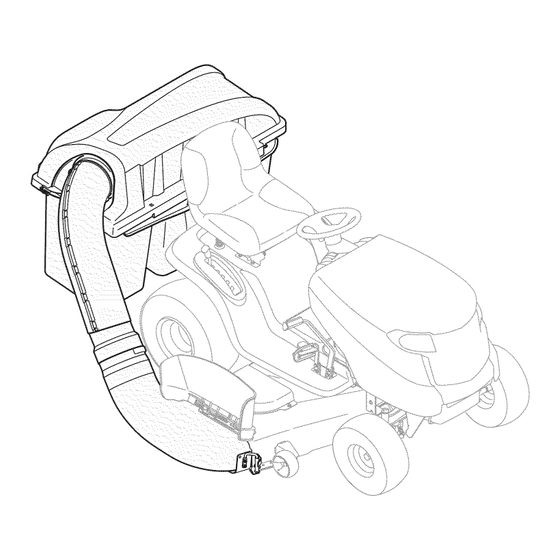
THREE BiN BAGGER
Model No. 247.24020
• Espanol,
p. 18
iMPORTANT:
Read and follow
all Safety
Rules and instructions
before
operating
this equipment.
For answers
to your questions
about
this product,
Call:
1-800=659=5917
Craftsman Tractor Help Line
7 am = 7 pm CT, Mort. =Sun.
Sears Brands
Management
Corporation,
Hoffman
Estates,
IL 60179 U.S.A.
Visit
our website:
www.sears.com/craftsman
FormNo.769-0%34A
(January 28, 2010)
Advertisement

Subscribe to Our Youtube Channel
Related Manuals for Craftsman 247.24020


Summary of Contents for Craftsman 247.24020
- Page 1 Call: Read and follow all Safety 1-800=659=5917 Rules and instructions before operating this equipment. Craftsman Tractor Help Line 7 am = 7 pm CT, Mort. =Sun. Sears Brands Management Corporation, Hoffman Estates, IL 60179 U.S.A. Visit our website: www.sears.com/craftsman...
- Page 2 16-17 Espa_ol ................Service Numbers ..........Back Cover Craftsman Full Warranty If this Craftsmanproductfails due to a defectin materialor workmanship withinone yearfrom the dateof purchase,returnit to any Searsstoreor otherCraftsmanoutlet in the UnitedStatesfor free replacement. This warrantycoversONLYdefectsin materialand workmanship.Searswill NOT payfor: •...
-
Page 3: California Proposition
This symbolpointsout importantsafetyinstructionswhich,if not This attachmentwas builtto be usedaccordingto the safeopera- followed,couldendangerthepersonalsafetyand/orpropertyof tion practicesin this manual.Carelessness or error on the part of yourselfand others. Readand followall instructionsin this manual the operatorcan resultin seriousinjury.Mowersare capableof beforeattemptingto operatethis machine.Failureto complywith amputatinghandsand feet and throwingobjects.Failureto observe these instructionsmay resultin personalinjury.Whenyou seethis the followingsafetyinstructionsas wellas the instructionsprovided symbol,HEEDITS WARNING! -
Page 4: Slope Operation
SLOPE OPERATION DO NOT: Slopesare a majorfactor relatedto lossof control andtip-overaccidents Do not turn on slopes unlessnecessary;then, turn slowlyand gradually whichcan resultinsevere injury or death.Attachmentscan also affect the downhill, if possible. stabilityof the machine.All slopes requireextra caution. Do not mow near drop-offs,ditchesor embankments. T he mowercould suddenlyturn over if a wheel is overthe edgeof a cliff,ditch, or if an For yoursafety,use the slope guideincludedas partof this manualto edge caves in. - Page 5 Use this pageas a guide to determineslopeswhereyoumay not operatesafely.Do not operate the lawnmoweron such slopes. This symbolpoints outimportantsafety instructionswhich,if not followed,could endangerthe personalsafetyand/or propertyof yourselfand others.Readand follow all instructionsin this manualbeforeattemptingto operatethis machine.Failureto complywith these instructionsmay result in personalinjury.Whenyou seethis symbol,HEEDITS WARNING!
- Page 6 Before beginning installation, remove allparts f rom the carton t omake s ure everything ispresent, Carton contents are listed b elow a nd shown below. Two h ardware packs areincluded inthis kitand aredetailed onthe following page. • HitchBracket Kit(3 Pcs.& HardwarePack) •...
- Page 7 This grasscollectorkit is shippedwith threehardwarepacksenclosed, Pleasecheckyourhardwarepacksagainstthe illustrationsbelow,The quantitiesforeach itemis listedin parenthesiswhilethe part numberis listed neareachitem. Hardware included with 689-00084 Hardware Pack 689-00163 712-04065 71o-3oo8 710-0276 712-04064 712-04063 Hardware Pack 689-00087 726-3046 © 710-3008 711-0309A 710-3015 712-04063 714-0117 71o-o4484 723-0476 ' _=_(3') 710-3168...
- Page 8 NOTE: References to left, right,front and rear of the tractorare from theoperator'sposition,unlessotherwisestated. • Beforeassembly,placethe tractoron a firm, levelsurface, disengagethe PTO,stop the tractorengine and set the parking brake. Forconvenience, p ivot the seatforwardand leaveit in that posi- tion untilthe grasscollectoris fully mountedand assembled. Assemble Mounting Brackets Toassemblethe baggermountingassembly,locate the mounting assemblypack and followthese steps:...
- Page 9 _%'_lign holeonbracket _ withholeontractor Figure4 Mount Assembly on Tractor Figure6 Install t he mountingassemblyon the tractoras follows: Installthe baggerhangerassemblyontothe mountingassembly Placethe hookedendsof the mountingassemblyoverthe on the tractorby hookingitoverthe hitch plateinthe center,lining shoulderbolts,as in Fig. 5, on the tractorand line up the hitch up the centermountinghole as seenin Fig.
- Page 10 Assembling Remaining Bagger Components Nowthat themountingbracketsare assembledand are inplaceon thetractor,followthese stepsto assemblethe remainingbagger components. Snapthe upper chutesupportin placeby firstclippingthe side portionontothe bin support rail.Alignthe edge of the snap featurewith the red line (1),as shownin the inset of Fig.9. Snapthe front portionof the upperchute supportto the bin supportrail as seen in2 of Fig.9.
- Page 11 Installthe grass binsontothe bin supportassemblyby inserting the front edge in first (1),as seenin Fig. 16,and settingthe back edge down(2) until it fits intothe assembly. Hinge Pin Figure13 Figure16 Attaching Blades Alwaysprotectyourhandswhileservicingbladesby wearingheavy work glovesor usingheavyrags. NOTE:Threehigh-liftbaggingbladesare includedinthe grass-catcher kit. Replacethe bladeswith these newbladesand savethe existing bladesas replacements or to reinstallon the bladespindleswhennot usingthe baggerkit.
- Page 12 Hex Nut Thehex flangenuthas a right-handed threadpattern.Donot attempt [to forcethe nutin wrongdirection;it may damagethe nutand create [a safetyhazard. Placea newbladeon eachspindleso that sideof the blade with part numberfacesthe groundwhenthe moweris in the operating position. NOTE:This baggerkit includestwo setsof blades,one set is for the50"...
- Page 13 Attaching Chute Stop Bracket Note: For all lawn tractors equipped with a 50-inch deck, secure the strap in the upper hole as shown in Fig. 21. Removethecarriageboltand lock nutholdingthe chute stopto Note: For all tractors equipped with a 54-inch deck, secure the the deck.See the left Insetof Fig.20.
- Page 14 With the baggercoveropen,install theupper chuteoverthe chute adapter,as seen in Fig.26, and rest the top sothat the chute NOTE: Forthechute elbowto be properlyinstalled,thebottomedge support sitsin the upperchutegroove.See Fig.27. mustfall belowthe bottomof the deck openingand the tab on topof theelbow shouldrestabovethedeck opening. Installthechuteadapterontothe chuteelbowbyliningup the tabsand slidingtheadapteroverthe chuteelbow,asin Fig.24.
- Page 15 Bagger Operation Removethe grass binsby liftingthem up (1 in Fig. 29) and away from the bin supportassembly(2). NOTE:Whenall threeof the grassbinsare full, placethetractoron a firm,levelsurface,disengagethe PTO(Blade Engage),turnthe tractor engineoff and set the parkingbrake. Flipthe seat up. Opengrass catchercover by pushingin on the rear,right-sidetab with yourright-hand,as seenin 1 of Fig.
- Page 17 931-04291 UpperChuteAssembly 931-04298 TripleBaggerCoverAssembly 731-06497 UpperChuteSupport 731-06504 BaggerCoverScreen 710-0276 CarriageScrew,5/16-18x 1.00" 710-3008 HexHeadScrew,5/16-18x .75" 711-0309A ClevisPin, .62"Dia. 964-04096A Grass-bagAssembly 683-04498A TripleBag SupportAssembly 683-04519 VerticalSupportBracket 711-05079 Cover HingePin 712-04063 FlangeLock Nut,5/16-18 735-0246A EndPlug 631-04300B DischargeChuteElbow,50/54"Deck 683-0617A-0637 Chute Stop-Bracket N/A* HitchBracket,RH N/A* Universal R earAttachmentBracket N/A* HitchBracket,LH...
- Page 18 Craftsman Total Garantia CraftsmanSi este productofalla debidoa un defectode materialo manode obra dentrode un aSoa partirde la fechade compra,el retornoa cualquierfiendaSearso cualquierotra Craftsmande salidaen los EstadosUnidospara la sustituci6ngratuita. EstagaranfiacubreQnicamente defectosde materialy manode obra. Searsno pagar&por: • Sustituci6nde las bolsas,que sonfungiblesque puedenIlevara cabo a partir de la utilizaci6nnormalen el periodode garanfia.
- Page 19 Esta rn_.quina r ue construidapara seroperadade acuerdocon La presenciade este sirnboloindicaque setrata de instrucciones las reglasde seguridadcontenidasen este rnanuakAI igualque irnportantesde seguridadque se deben respetarpara evitar concualquiertipo de equipo rnotorizado, u n descuidoo error por poner en peligrosu seguridadpersonaly/o materialy la de otras partedel operadorpuedeproducirlesionesgraves.Esta rn_.quina personas.Lea y siga todaslas instruccionesde este manualantes es capazde arnputarrnanosy piesy de arrojarobjetoscon gran...
- Page 20 Siga las recomendaciones del fabricante sobre pesos y Servid0 general contrapesos de las ruedas, para mejorar la estabilidad. Antes de limpiar, reparar o inspeccionar la m_quina, Haga que todos los movimientos en las pendientes sean compruebe que las cuchillas y todas las piezas m6viles se lentos y graduales.
- Page 21 Utiliceesta p_.gina cornouna guia paradeterrninarzonasde laderadondeno puedeoperarde forrnasegura.Nooperar la cortadorade cesped en pendientestales. Este sirnbolose_alaa cabo lasinstruccionesde seguridadirnportantesque,si no se siguen,podriaponer en peligrola seguridadpersonaly / o la propiedad de si rnisrnoy losdern_.s. L ea y siga las instrucciones en este manualantesde intentaroperar esta rn_.quina. El incurnplirniento de estas instrucciones puede resultaren lesionespersonales.Cuandoveaeste sirnbolo,prestaratenci6na sus iADVERTENCIA!
- Page 22 Antes de comenzarla instalaci6n, r etiretodas las piezasde la cajapara asegurarsede que tienetodo. El contenidode la cajase indicaa continuaci6ny se ilustraen la Fig. 3-1.Este kit incluyedos paquetesde herrajesque se detallanen la p_.gina siguiente. Cubiertade lasbisagrasPin HitchBracket Kit(3 pcs. Hardware& Pack) Chutetubode extensi6n •...
- Page 23 Estejuego colectorde c_spedse enviacon un paquetesde herrajessueltosincluidos, Porfavor controleel contenidode los paquetescon las ilustradonessiguientes,La canfidadde cadaelementoapareceentrepar_ntesisy el nQmero de piezacerca de cadaelemento, Hardware included with 689-00084 Hardware Pack 689-00163 712-04065 710-3008 710-0276 712-04064 712-04063 Hardware Pack 689-00087 726-3046 © 710-3008 711-0309A 710-3015 712-04063...
- Page 24 NOTA: Lasreferenciasa izquierda,derecha,partedelanteray trasera del tractorsondesdela posici6ndel operador,salvoindicaci6nen contrario. • Antesde armar,coloqueel tractorsobreuna superficiefirme y nivelada,desenganche la toma de fuerza (PTO),detengael motordel tractory coloqueel freno de mano. • Paramayorcomodidad,gire el asientohaciaadelantey d_jelo en esa posici6nhastaque el colectorde pastoest_ totalmente armadoy montado. Armado de las m_nsulas de montaje Paraarmarla unidadde montajede la embolsadora,Iocaliceel paquetede la unidadde montajey sigaestospasos:...
- Page 25 Alinee el orificio la m_nsula con el del tractor Figura 4 Monte la unidad en el tractor Figura6 Instalela unidadde montajesobreel tractorde esta manera: Instalela unidadde suspensi6ndel recolectoren la unidadde Coloquelos extremoscon ganchode la unidadde montajesobre montajedel tractorenganch_.ndolo s obrela placade enganche los pernoscon reborde,cornoen la Fig.5, en el tractory alinee del centro,alineandoel orificiode montajecentralcomo se ve en el orificiocentralde la m_nsulade soportede enganchecon el...
- Page 26 Armado del resto de los componentes dei recolector Unavez que las rn_nsulasde rnontajeest_narmadasy colocadasen el tractor,siga estospasospara arrnarel resto de los cornponentes de la ernbolsadora. Calcea presi6nel soportedel canalsuperiorcolocandoprirnero el lateralsobreel riel de soportedel cubocon el hordeque calza a presi6nalineadoconla linea roja (1),cornose ve en el recuadro de la Fig.
- Page 27 Instalelos cubosen su unidadde soporte insertandoprirneroel hordedelantero(1),cornoseve en la Fig. 16,y bajandoel horde posteriorhastaque calce en la unidad. bisagra Figura 13 Figura 15 Colocaci6n de cuchillas uantesindustrialeso traposgruesos.. NOTA:Se incluyentres cuchillasernbolsadoras high-liftcon el kit de recolecci6nde c_sped.Reernplace las cuchillasconestascuchillas nuevasy guardelas otras cornorepuestoo para reinstalaren los husillosde las cuchillascuandono se usael kit de recolecci6n.
- Page 28 Tuercahexagonal //; La roscade la tuerca hexagonal c onbrida gira hacia la derecha.No intenteforzarla tuercaen la direcci6nopuesta;puededaSarlay crear un riesgode seguridad. Coloqueuna cuchillanuevaen cadahusillode forrnaque el lado conel nQrnero de piezamiraal suelocuandola cortadoraest,. en cubierta posicidnde funcionarniento. NOTA:]Estekit de ernbolsadora incluyedosjuegos de cuchillas, uno para la plataforrna de 50"y el otto para la plataforrna de 54".
- Page 29 NOATA:Paratodos los tractoresde jardin equipadoconun JnstaJaci6n deJ soporte del tope de canaJ paquetede 50-pulgadas, s egurode la correaen el orificiode la Retireel pernode carroy tuercade seguridadque sujetanel tope partesuperiorcomose muestraen la figura.20. de canala la plataforma.Veael recuadroizquierdo d e la Fig. lg. Guardelos herrajes.
- Page 30 NOTA: Parainstalarcorrectamenteel codo del canal,el borde inferior Con la cubierta de la embolsadora abierta,instaleel canal debecaer debajode la parte inferiorde la aberturade la plataforma superiorsobreel adaptador,comose ve en la Fig. 25, y apoye y la leng(Jeta de la partesuperiordel cododebe descansarsobrela la partesuperiorparaque el soportedel canaldescanseen la aberturade la plataforma.
- Page 31 Funcionamientode la embolsadora Elirninar los cubos de la hierbapor levantaflashasta(1 en la figura. 30) y fuerade la asarnbleade apoyobin (2). NOTA:Cuandolosdos cubospara cespedest_n lenos, coloqueel tractorsobreuna superficiefirrney nivelada,desenganche la torna de fuerza (PTO),apagueel motordel tractory coloqueel frenode estacionarniento. Volt,eel asientohaciaarriba. Abra la cubiertade cespedernpujando en la parte trasera,lado derechode la ficha con su rnanoderecha,cornose veen la figura 1.29, y de levantarcon la rnanoizquierdaen el centrode la parte...
- Page 32 Your Home For troubleshooting, product manuals and home solutions advice: ÷anag÷ www.managemyhome.com For repair - in your home - of all major brand appliances, lawn and garden equipment, or heating and cooling systems, no matter who made it, no matter who sold it! For the replacement parts, accessories owner's manuals that you need to do-it-yourself.
Need help?
Do you have a question about the 247.24020 and is the answer not in the manual?
Questions and answers