Advertisement
Available languages
Available languages
Quick Links
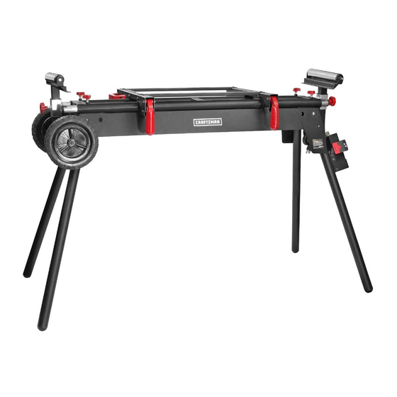
DELUXE MITER SAW STAND
Model No. 320. 16490
WARNING: To reduce the risk of injury,
the user must read and understand
the
Operator's Manual before using this product.
_WARNING:
To reduce
the risk of injury,
the user must always read and follow
all instructions
in the bench
top tool
operating
manual
before mounting
the
tool to this stand.
• WARRANTY
• SAFETY
• ASSEMBLY
• DESCRiPTiON
• OPERATION
• MAINTENANCE
• ESPANOL
Sears Brands Management
Corporation, Hoffman Estates,
IL 60179
U.S.A.
www,craftsman,com
Advertisement

Related Manuals for Craftsman 320.16490


Summary of Contents for Craftsman 320.16490
- Page 1 • OPERATION the user must always read and follow • MAINTENANCE all instructions in the bench top tool • ESPANOL operating manual before mounting tool to this stand. Sears Brands Management Corporation, Hoffman Estates, IL 60179 U.S.A. www,craftsman,com...
- Page 2 For warranty coverage details to obtain free replacement, visit the web site: www.craftsman.com This warranty is void if this product is ever used while providing commercial services or if rented to another person. This warranty gives you specific legal rights, and you may also have other rights which vary from state to state.
- Page 3 _,WARNING: Some dust created by power sanding, sawing, grinding, drilling and other construction activities contains chemicals known to the state of California to cause cancer, birth defects or other reproductive harm. Some examples of these chemicals are: • Lead from lead-based paints, Crystalline silica from bricks and cement...
- Page 4 ,_ WARNING: Be sure to read and understand all safety instructions in this Operator's Manual, including all safety alert symbols such as "DANGER", "WARNING", and "CAUTION" before using this stand. Failure to follow all instructions listed below may result in electric shock, fire, and/or serious personal injury.
- Page 5 SAVE THESE iNSTRUCTiONS Some of the following symbols may be used on this tool. Please study them and learn their meaning. Proper interpretation of these symbols will allow you to operate the tool better and more safely. SYMBOL NAME DESIGNATION/EXPLANATION Volts Voltage Amperes...
- Page 6 GENERAL SAFETY RULES WARNING: Read and understand all instructions. Failure to follow all instructions in this Operator's Manual may result in electric shock, fire, and/or serious personal injury. Save all warnings and instructions for future reference. READ AND SAVE THESE INSTRUCTIONS CAUTION: Do not modify or use this stand for any application other than...
- Page 7 • Store properly. Do not store the miter saw stand outdoors or in a damp location. • Do not stand or climb on miter saw stand. It could tip over, causing serious injury. • Do not permit children to use the stand unsupervised.
- Page 8 KNOW YOUR MITER SAW WORK STAND (Fig. 1} Fig. 1 Frame assembly Extension bar locking knob including legs Cross support Roller- locking knob }witch Lockin_ lever Quick-release assembly mounting brackets wheel Cord Cable hook PRODUCT SEPCIFICATIONS Input voltage 125V AC Switch Rating Input ampere...
- Page 9 WARNING: If any parts are broken or missing, do not attempt to operate the stand until the broken or missing part is replaced. Failure to do so could result in possible serious injury. WARNING: Do not attempt to modify this stand or create accessories recommended for use with this stand.
- Page 10 Spring washer Extension bar locking knob Roller-assembly locking knob Roller assembly Transport wheel Wheel clasp Wheel mounting axle assembly Wheel mounting bolt Wheel mounting Page 10 16490 ManuaLRevised_12 0604...
- Page 11 ,_b, WARNING: Do not use this stand as scaffolding or as a ladder. Make sure to tighten all locking knobs and levers securely prior to use, Maximum capacity 330 Ibs. Power tools on the stand should not exceed a combined overall height of 60 inches from the floor.
- Page 12 iNSTALL THE WHEELS ONTO THE LEGS Use a wheel mounting bolt (R) and mounting nut (S) to attach Fig. 5 the wheel mounting axle assembly (Q) on the stand. Place the wheel (N) on the axle so that the axle extends through the wheel...
- Page 13 With the miter saw mounted Fig. 7 on the quick-release mounting brackets, place the assembly on the work stand (Fig. 7). iNSTALLiNG THE QUICK=RELEASE MOUNTING BRACKETS Hold the quick-release mounting bracket (B) by the handles. Position the area designated "Z" in Fig. 8 on the frame Fig.
- Page 14 Mounting Non=Standard Miter Saws NOTICE: This configuration allows for miter saws on which the 4 mounting holes holes form a trapezoid pattern (some saws) and the those on which the 3 mounting holes form a triangular pattern (few saws). Place two support bars (C) Fig.
- Page 15 With the miter saw mounted on the quick-release mounting brackets (B), place the assembly onto the work stand (Fig. 13). MOUNTING THE ROLLER ASSEMBLIES Insert the roller assemblies into the mounting slots (Fig. 14). Adjust the height of the roller Fig.
- Page 16 ROLLER OPERATION When working on a long workpiece, the extension bars and rollers are needed. The roller can be used as a stationary stop guide or a single directional roller. • When using the roller as stop Fig. 16 Stop guide guide, place the workpiece Steel plate the plate;...
- Page 17 MOVING THE STAND Fig. 19 WARNING: Before moving your work stand, always fully tighten all the mounting bolts and nuts. Failure to do so could result in serious personal injury. Place the stand assembly on its side on a flat surface as shown in Fig.
- Page 18 SWITCH ASSEMBLY OPERATION Fig. 22 The switch has a safety key to help prevent accidentally switching the tool on and the unauthorized, possibly hazardous use by others. The safety key (red) must be completely inserted into the switch before the switch panel (black) can be turned ON (Figs.
- Page 19 To operate the switch (Fig. 25) Fig. 25 Make sure that the safety key is inserted into the switch panel. To turn the power ON, lift up the ON/OFF switch panel. To turn the power OFF, press the ON/OFF switch panel.
- Page 20 ,_ WARNING: When servicing, use only identical replacement parts. Use of any other parts may create a hazard or cause product damage. GENERAL MAINTENANCE Avoid using solvents when cleaning plastic parts. Most plastics are susceptible to damage from various types of commercial solvents and may be damaged their use.
- Page 21 DELUXE MITER SAW STAND MODEL NO. 320.16490 The Model Number will be found on the Nameplate attached to the support of the bench grinder stand. Always mention the Model Number when ordering parts for this tool. To order parts, call 1-800-469-4663. 16490 Manual_Revised_12-0604 Page 21...
- Page 22 DELUXE MITER SAW STAND MODEL NO. 320.16490 The Model Number will be found on the Nameplate attached to the support of the bench grinder stand. Always mention the Model Number when ordering parts for this tool. To order parts, call 1-800-469-4663. 1010602005 Shield ring 1020220002...
- Page 23 1010119002 Screw 1020102001 Handle 1010108006 Blot 1010201004 1010402012 Bolt 1010103010 Bolt 1010301030 Washer 1010103009 Bolt 2040307001 Connecting plate 1021601001 Square block 102102001 Screw 2040803003 Frame assembly 1029913012 Switch assembly 1010122009 Screw 2029903007 1021503001 Block 1010118004 Bolt 1010407001 Bolt 1010603017 Spring 1010202001 1010301001 Washer...
- Page 24 ADVERTENCIA: Para reducir el riesgo • MANTENIMIENTO de lesiones, el usuario siempre debe leer • ESPANOL y seguir las instrucciones del manual del propietario de la herramienta antes de instalarla. Sears Brands Management Corporation, Hoffman Estates, IL 60179 U.S.A. www,craftsman,com...
- Page 25 Paginas 32-33 Operacion Paginas 11-19 Mantenimiento Pagina 20 Lista de piezas Paginas 21-23 GARANTiA TOTAL DE UN A_lO DE CRAFTSMAN POR UN ANO despues de la fecha de compra, este producto esta garantizado por cualquier defecto de materiales o fabricaci6n.
- Page 26 ADVERTENClA: Algunas particulas de polvo que se generan al lijar, serruchar, afilar, o perforar, con herramientas electricas, asi como las actividades de construccion, contienen quimicos que el estado de California reconoce como causantes de cancer, nacimientos defectuosos u otros daSos reproductivos.
- Page 27 ADVERTENClA: AsegOrese de leer y comprender todas las instrucciones de seguridad en este manual de operacion, incluyendo todos los simbolos de seguridad de alerta tales como "PELIGRO", "ADVERTENClA", "PRECAUClON" antes de usar esta herramienta. El no seguir todas las instrucciones que se indican a continuacion, puede ocasionar descarga...
- Page 28 GUARDE ESTAS INSTRUCCIONES Algunos de los siguientes simbolos pueden usarse en esta herramienta. favor est6dielos y aprenda su significado. La interpretacion adecuada de estos simbolos, le permitir& operar mejor la herramienta y de una forma mas segura. SJMBOLO NOMBRE DESIGNACl6N / EXPLICACl6N Voltios Voltaje...
- Page 29 ADVERTENCIAS DE SEGURIDAD GENERALES ADVERTENCIA: Lea y comprenda todas las instrucciones. No seguir todas las instrucciones de este Manual del Propietario puede generar una descarga electrica, un incendio y/o graves lesiones corporales. Conserve todas las advertencias e instrucciones para referencia futura.
- Page 30 • Solo utilice su soporte de sierra de inglete sobre una superficie resistente, seca y plana. • Mantenga el _rea de trabajo lirnpia y bien iluminada. Las &reas desordenadas u oscuras son propicias para los accidentes. No se estire de m&s. Mantenga una postura equilibrada y segura en todo momento.
- Page 31 CONOZCA EL SOPORTE DE TRABAJO DE LA SIERRA DE INGLETE (Fig. 1} Fig. 1 Perilla de bloqueo Montaje de armazon Barra de barra de extension incluyendo patas soporte cruzada e de rodillo Perilla de bloqueo de rodillo Montaje del interruptor Soportes de montaje Palanca...
- Page 32 ,_k ADVERTENClA: Si falta alguna pieza o si alguna pieza estA rota, no trate de utilizar el soporte hasta que se haya reemplazado dicha pieza. No hacerlo puede provocar una lesion personal grave. ADVERTENClA: No trate de modificar este soporte o crear accesorios recomendados para usar con esta unidad.
- Page 33 Arandela de resorte Tuerca Perilla de bloqueo de barra de extension Perilla de bloqueo de montaje de rodillo Montaje de rodillo Rueda para transporte Presilla para rueda Montaje de eje de montaje de rueda Perno de montaje de rueda Tuerca de montaje de rueda Page 33 16490...
- Page 34 ADVERTENCIA: No utilice este soporte como un andamio o escalera. Aseg0rese de ajustar todas las perillas de bloqueo y palancas firmemente antes de usar. La capacidad m&xima es de 330 Ibs. Las herramientas electricas instaladas sobre el soporte no deben superar una altura total combinada de 60 pulgadas...
- Page 35 INSTALE LAS RUEDAS EN LAS PATAS Utilice un perno de montaje de rueda (R) y tuerca de montaje Fig. 5 (S) para sujetar el montaje de eje de rueda (Q) al soporte. Coloque la rueda (N) en el eje para que este se extienda a traves de la rueda (N).
- Page 36 C6mo instalar ias sierras de inglete estAndar al soporte AVISO: Esta configuracion acepta sierras de inglete en las cuales los 4 orificios de montaje forman un patron rectangular (la mayoria de las sierras de inglete). Instale la sierra de inglete en los soportes de montaje de liberacion...
- Page 37 Ajuste la palanca de bloqueo Fig. 9 Palanca para trabar los soportes montaje (B) (Fig. 9). C6rno instalar sierras de inglete no est_ndar AVISO: Esta configuracion acepta sierras de inglete en las cuales los 4 orificios de montaje forman un patron trapezoide (algunas sierras) y aquellas en las cuales los 3 orificios...
- Page 38 Coloque la sierra de inglete Fig. 12 con orificios de montaje estandar en las barras de soporte cruzadas (C). Controle la posicion y ajuste las barras de soporte lentamente para que los orificios de montaje de la sierra de inglete esten alineados con las ranuras de las barras de soporte cruzadas...
- Page 39 Trabe el montaje de rodillo en Fig. 15 posici6n ajustando la perilla de bloqueo (K) (Fig. 15). Tambien puede usarse un montaje de rodillo como una guia de tope fija para cortes repetitivos. FUNCIONAMIENTO DEL RODILLO Cuando trabaje con una pieza de trabajo larga, se necesitan barras de extension...
- Page 40 COMO TRASLADAR EL SOPORTE Fig. 19 ADVERTENClA: Antes de trasladar el soporte de trabajo, siempre ajuste por completo pemos y tuercas de montaje. hacerlo puede provocar una lesion personal grave. Coloque el montaje armazon sobre su lado en una superficie plana como se indica en la Fig.
- Page 41 FUNCIONAMIENTO Fig. 22 MONTAJE DEL INTERRUPTOR El interruptor tiene una Ilave de seguridad para evitar el encendido accidental de la herramienta y el uso sin autorizacion posiblemente peligroso por parte de otras personas. La Ilave de seguridad (roja) debe introducirse por completo en el interruptor...
- Page 42 Para operar el interruptor Fig. 25 (Fig. 25) Verifique que la Ilave de seguridad este introducida dentro del panel del interruptor. Para encender la energia (ON), jale hacia arriba el panel del interruptor ON/OFF (encendido/apagado). Para apagar la energia (OFF), presione hacia abajo el panel del interruptor ON/OFF (encendido/apagado).
- Page 43 ADVERTENClA: Cuando realice mantenimiento, solo utilice piezas de repuesto identicas. El uso de otras piezas puede generar un riesgo o provocar dafios al producto. MANTENIMIENTO GENERAL Evite usar solventes cuando limpie piezas plasticas. La mayoria de los plasticos son susceptibles a dafios pot parte de varios tipos de solventes comerciales pueden dafiarse pot su uso.
- Page 44 SOPORTE DE SIERRA DE INGLETE DE LUJO N ° 320.16490 El nOmero de modelo se encuentra en la placa sujeta a la pata de soporte soporte. Siempre mencione el nOmero de modelo cuando solicite repuestos para esta herramienta. Para solicitar repuestos, Ilame al 1-800-469-4663.
- Page 45 SOPORTE DE SIERRA DE INGLETE DE LUJO N ° 320.16490 El nOmero de modelo se encuentra en la placa sujeta a la pata de soporte del soporte. Siempre mencione el nOmero de modelo cuando solicite repuestos para esta herramienta. Para solicitar repuestos, Ilame al 1-800-469-4663.
- Page 46 1010119002 Tornillo 1020102001 Manija 1010108006 Perno 1010201004 Tuerca 1010402012 Perno 1010103010 Perno 1010301030 Arandela 1010103009 Perno 2040307001 Placa de conexion 1021601001 Bloque cuadrado 102102001 Tornillo 2040803003 Montaje de armazon 1029913012 Montaje del interruptor 1010122009 Tornillo 2029903007 Pata 1021503001 Bloque 1010118004 Perno 1010407001 Perno...
- Page 47 • OPERATION the user must always read and follow • MAINTENANCE all instructions in the bench top tool • ESPANOL operating manual before mounting tool to this stand. Sears Brands Management Corporation, Hoffman Estates, IL 60179 U.S.A. www,craftsman,com...
- Page 48 For warranty coverage details to obtain free replacement, visit the web site: www.craftsman.com This warranty is void if this product is ever used while providing commercial services or if rented to another person. This warranty gives you specific legal rights, and you may also have other rights which vary from state to state.
- Page 49 _,WARNING: Some dust created by power sanding, sawing, grinding, drilling and other construction activities contains chemicals known to the state of California to cause cancer, birth defects or other reproductive harm. Some examples of these chemicals are: • Lead from lead-based paints, Crystalline silica from bricks and cement...
- Page 50 ,_ WARNING: Be sure to read and understand all safety instructions in this Operator's Manual, including all safety alert symbols such as "DANGER", "WARNING", and "CAUTION" before using this stand. Failure to follow all instructions listed below may result in electric shock, fire, and/or serious personal injury.
- Page 51 SAVE THESE iNSTRUCTiONS Some of the following symbols may be used on this tool. Please study them and learn their meaning. Proper interpretation of these symbols will allow you to operate the tool better and more safely. SYMBOL NAME DESIGNATION/EXPLANATION Volts Voltage Amperes...
- Page 52 GENERAL SAFETY RULES WARNING: Read and understand all instructions. Failure to follow all instructions in this Operator's Manual may result in electric shock, fire, and/or serious personal injury. Save all warnings and instructions for future reference. READ AND SAVE THESE INSTRUCTIONS CAUTION: Do not modify or use this stand for any application other than...
- Page 53 • Store properly. Do not store the miter saw stand outdoors or in a damp location. • Do not stand or climb on miter saw stand. It could tip over, causing serious injury. • Do not permit children to use the stand unsupervised.
- Page 54 KNOW YOUR MITER SAW WORK STAND (Fig. 1} Fig. 1 Frame assembly Extension bar locking knob including legs Cross support Roller- locking knob }witch Lockin_ lever Quick-release assembly mounting brackets wheel Cord Cable hook PRODUCT SEPCIFICATIONS Input voltage 125V AC Switch Rating Input ampere...
- Page 55 WARNING: If any parts are broken or missing, do not attempt to operate the stand until the broken or missing part is replaced. Failure to do so could result in possible serious injury. WARNING: Do not attempt to modify this stand or create accessories recommended for use with this stand.
- Page 56 Spring washer Extension bar locking knob Roller-assembly locking knob Roller assembly Transport wheel Wheel clasp Wheel mounting axle assembly Wheel mounting bolt Wheel mounting Page 10 16490 ManuaLRevised_12 0604...
- Page 57 ,_b, WARNING: Do not use this stand as scaffolding or as a ladder. Make sure to tighten all locking knobs and levers securely prior to use, Maximum capacity 330 Ibs. Power tools on the stand should not exceed a combined overall height of 60 inches from the floor.
- Page 58 iNSTALL THE WHEELS ONTO THE LEGS Use a wheel mounting bolt (R) and mounting nut (S) to attach Fig. 5 the wheel mounting axle assembly (Q) on the stand. Place the wheel (N) on the axle so that the axle extends through the wheel...
- Page 59 With the miter saw mounted Fig. 7 on the quick-release mounting brackets, place the assembly on the work stand (Fig. 7). iNSTALLiNG THE QUICK=RELEASE MOUNTING BRACKETS Hold the quick-release mounting bracket (B) by the handles. Position the area designated "Z" in Fig. 8 on the frame Fig.
- Page 60 Mounting Non=Standard Miter Saws NOTICE: This configuration allows for miter saws on which the 4 mounting holes holes form a trapezoid pattern (some saws) and the those on which the 3 mounting holes form a triangular pattern (few saws). Place two support bars (C) Fig.
- Page 61 With the miter saw mounted on the quick-release mounting brackets (B), place the assembly onto the work stand (Fig. 13). MOUNTING THE ROLLER ASSEMBLIES Insert the roller assemblies into the mounting slots (Fig. 14). Adjust the height of the roller Fig.
- Page 62 ROLLER OPERATION When working on a long workpiece, the extension bars and rollers are needed. The roller can be used as a stationary stop guide or a single directional roller. • When using the roller as stop Fig. 16 Stop guide guide, place the workpiece Steel plate the plate;...
- Page 63 MOVING THE STAND Fig. 19 WARNING: Before moving your work stand, always fully tighten all the mounting bolts and nuts. Failure to do so could result in serious personal injury. Place the stand assembly on its side on a flat surface as shown in Fig.
- Page 64 SWITCH ASSEMBLY OPERATION Fig. 22 The switch has a safety key to help prevent accidentally switching the tool on and the unauthorized, possibly hazardous use by others. The safety key (red) must be completely inserted into the switch before the switch panel (black) can be turned ON (Figs.
- Page 65 To operate the switch (Fig. 25) Fig. 25 Make sure that the safety key is inserted into the switch panel. To turn the power ON, lift up the ON/OFF switch panel. To turn the power OFF, press the ON/OFF switch panel.
- Page 66 ,_ WARNING: When servicing, use only identical replacement parts. Use of any other parts may create a hazard or cause product damage. GENERAL MAINTENANCE Avoid using solvents when cleaning plastic parts. Most plastics are susceptible to damage from various types of commercial solvents and may be damaged their use.
- Page 67 DELUXE MITER SAW STAND MODEL NO. 320.16490 The Model Number will be found on the Nameplate attached to the support of the bench grinder stand. Always mention the Model Number when ordering parts for this tool. To order parts, call 1-800-469-4663. 16490 Manual_Revised_12-0604 Page 21...
- Page 68 DELUXE MITER SAW STAND MODEL NO. 320.16490 The Model Number will be found on the Nameplate attached to the support of the bench grinder stand. Always mention the Model Number when ordering parts for this tool. To order parts, call 1-800-469-4663. 1010602005 Shield ring 1020220002...
- Page 69 1010119002 Screw 1020102001 Handle 1010108006 Blot 1010201004 1010402012 Bolt 1010103010 Bolt 1010301030 Washer 1010103009 Bolt 2040307001 Connecting plate 1021601001 Square block 102102001 Screw 2040803003 Frame assembly 1029913012 Switch assembly 1010122009 Screw 2029903007 1021503001 Block 1010118004 Bolt 1010407001 Bolt 1010603017 Spring 1010202001 1010301001 Washer...
- Page 70 ADVERTENCIA: Para reducir el riesgo • MANTENIMIENTO de lesiones, el usuario siempre debe leer • ESPANOL y seguir las instrucciones del manual del propietario de la herramienta antes de instalarla. Sears Brands Management Corporation, Hoffman Estates, IL 60179 U.S.A. www,craftsman,com...
- Page 71 Paginas 32-33 Operacion Paginas 11-19 Mantenimiento Pagina 20 Lista de piezas Paginas 21-23 GARANTiA TOTAL DE UN A_lO DE CRAFTSMAN POR UN ANO despues de la fecha de compra, este producto esta garantizado por cualquier defecto de materiales o fabricaci6n.
- Page 72 ADVERTENClA: Algunas particulas de polvo que se generan al lijar, serruchar, afilar, o perforar, con herramientas electricas, asi como las actividades de construccion, contienen quimicos que el estado de California reconoce como causantes de cancer, nacimientos defectuosos u otros daSos reproductivos.
- Page 73 ADVERTENClA: AsegOrese de leer y comprender todas las instrucciones de seguridad en este manual de operacion, incluyendo todos los simbolos de seguridad de alerta tales como "PELIGRO", "ADVERTENClA", "PRECAUClON" antes de usar esta herramienta. El no seguir todas las instrucciones que se indican a continuacion, puede ocasionar descarga...
- Page 74 GUARDE ESTAS INSTRUCCIONES Algunos de los siguientes simbolos pueden usarse en esta herramienta. favor est6dielos y aprenda su significado. La interpretacion adecuada de estos simbolos, le permitir& operar mejor la herramienta y de una forma mas segura. SJMBOLO NOMBRE DESIGNACl6N / EXPLICACl6N Voltios Voltaje...
- Page 75 ADVERTENCIAS DE SEGURIDAD GENERALES ADVERTENCIA: Lea y comprenda todas las instrucciones. No seguir todas las instrucciones de este Manual del Propietario puede generar una descarga electrica, un incendio y/o graves lesiones corporales. Conserve todas las advertencias e instrucciones para referencia futura.
- Page 76 • Solo utilice su soporte de sierra de inglete sobre una superficie resistente, seca y plana. • Mantenga el _rea de trabajo lirnpia y bien iluminada. Las &reas desordenadas u oscuras son propicias para los accidentes. No se estire de m&s. Mantenga una postura equilibrada y segura en todo momento.
- Page 77 CONOZCA EL SOPORTE DE TRABAJO DE LA SIERRA DE INGLETE (Fig. 1} Fig. 1 Perilla de bloqueo Montaje de armazon Barra de barra de extension incluyendo patas soporte cruzada e de rodillo Perilla de bloqueo de rodillo Montaje del interruptor Soportes de montaje Palanca...
- Page 78 ,_k ADVERTENClA: Si falta alguna pieza o si alguna pieza estA rota, no trate de utilizar el soporte hasta que se haya reemplazado dicha pieza. No hacerlo puede provocar una lesion personal grave. ADVERTENClA: No trate de modificar este soporte o crear accesorios recomendados para usar con esta unidad.
- Page 79 Arandela de resorte Tuerca Perilla de bloqueo de barra de extension Perilla de bloqueo de montaje de rodillo Montaje de rodillo Rueda para transporte Presilla para rueda Montaje de eje de montaje de rueda Perno de montaje de rueda Tuerca de montaje de rueda Page 33 16490...
- Page 80 ADVERTENCIA: No utilice este soporte como un andamio o escalera. Aseg0rese de ajustar todas las perillas de bloqueo y palancas firmemente antes de usar. La capacidad m&xima es de 330 Ibs. Las herramientas electricas instaladas sobre el soporte no deben superar una altura total combinada de 60 pulgadas...
- Page 81 INSTALE LAS RUEDAS EN LAS PATAS Utilice un perno de montaje de rueda (R) y tuerca de montaje Fig. 5 (S) para sujetar el montaje de eje de rueda (Q) al soporte. Coloque la rueda (N) en el eje para que este se extienda a traves de la rueda (N).
- Page 82 C6mo instalar ias sierras de inglete estAndar al soporte AVISO: Esta configuracion acepta sierras de inglete en las cuales los 4 orificios de montaje forman un patron rectangular (la mayoria de las sierras de inglete). Instale la sierra de inglete en los soportes de montaje de liberacion...
- Page 83 Ajuste la palanca de bloqueo Fig. 9 Palanca para trabar los soportes montaje (B) (Fig. 9). C6rno instalar sierras de inglete no est_ndar AVISO: Esta configuracion acepta sierras de inglete en las cuales los 4 orificios de montaje forman un patron trapezoide (algunas sierras) y aquellas en las cuales los 3 orificios...
- Page 84 Coloque la sierra de inglete Fig. 12 con orificios de montaje estandar en las barras de soporte cruzadas (C). Controle la posicion y ajuste las barras de soporte lentamente para que los orificios de montaje de la sierra de inglete esten alineados con las ranuras de las barras de soporte cruzadas...
- Page 85 Trabe el montaje de rodillo en Fig. 15 posici6n ajustando la perilla de bloqueo (K) (Fig. 15). Tambien puede usarse un montaje de rodillo como una guia de tope fija para cortes repetitivos. FUNCIONAMIENTO DEL RODILLO Cuando trabaje con una pieza de trabajo larga, se necesitan barras de extension...
- Page 86 COMO TRASLADAR EL SOPORTE Fig. 19 ADVERTENClA: Antes de trasladar el soporte de trabajo, siempre ajuste por completo pemos y tuercas de montaje. hacerlo puede provocar una lesion personal grave. Coloque el montaje armazon sobre su lado en una superficie plana como se indica en la Fig.
- Page 87 FUNCIONAMIENTO Fig. 22 MONTAJE DEL INTERRUPTOR El interruptor tiene una Ilave de seguridad para evitar el encendido accidental de la herramienta y el uso sin autorizacion posiblemente peligroso por parte de otras personas. La Ilave de seguridad (roja) debe introducirse por completo en el interruptor...
- Page 88 Para operar el interruptor Fig. 25 (Fig. 25) Verifique que la Ilave de seguridad este introducida dentro del panel del interruptor. Para encender la energia (ON), jale hacia arriba el panel del interruptor ON/OFF (encendido/apagado). Para apagar la energia (OFF), presione hacia abajo el panel del interruptor ON/OFF (encendido/apagado).
- Page 89 ADVERTENClA: Cuando realice mantenimiento, solo utilice piezas de repuesto identicas. El uso de otras piezas puede generar un riesgo o provocar dafios al producto. MANTENIMIENTO GENERAL Evite usar solventes cuando limpie piezas plasticas. La mayoria de los plasticos son susceptibles a dafios pot parte de varios tipos de solventes comerciales pueden dafiarse pot su uso.
- Page 90 SOPORTE DE SIERRA DE INGLETE DE LUJO N ° 320.16490 El nOmero de modelo se encuentra en la placa sujeta a la pata de soporte soporte. Siempre mencione el nOmero de modelo cuando solicite repuestos para esta herramienta. Para solicitar repuestos, Ilame al 1-800-469-4663.
- Page 91 SOPORTE DE SIERRA DE INGLETE DE LUJO N ° 320.16490 El nOmero de modelo se encuentra en la placa sujeta a la pata de soporte del soporte. Siempre mencione el nOmero de modelo cuando solicite repuestos para esta herramienta. Para solicitar repuestos, Ilame al 1-800-469-4663.
- Page 92 1010119002 Tornillo 1020102001 Manija 1010108006 Perno 1010201004 Tuerca 1010402012 Perno 1010103010 Perno 1010301030 Arandela 1010103009 Perno 2040307001 Placa de conexion 1021601001 Bloque cuadrado 102102001 Tornillo 2040803003 Montaje de armazon 1029913012 Montaje del interruptor 1010122009 Tornillo 2029903007 Pata 1021503001 Bloque 1010118004 Perno 1010407001 Perno...