Table of Contents
Advertisement
Quick Links
Advertisement
Table of Contents

Related Manuals for Epson TP1


Summary of Contents for Epson TP1
- Page 1 RC170 Option Teach Pendant Rev.5 EM079P1591F...
- Page 3 RC170 Option Teach Pendant T P1 Rev.5 Copyright © 2006-2007 SEIKO EPSON CORPORATION. All rights reserved. TP1 Rev.5...
- Page 4 2. If you do not follow the WARNINGS and CAUTIONS in this manual, we cannot be responsible for any malfunction or accident, even if the result is injury or death. 3. We cannot foresee all possible dangers and consequences. Therefore, this manual cannot warn the user of all possible hazards. TP1 Rev.5...
- Page 5 Please prepare the following items before you contact us. - Your controller model and its serial number - Your manipulator model and its serial number - Software and its version in your robot system - A description of the problem SERVICE CENTER TP1 Rev.5...
- Page 6 Following descriptions are indicated throughout the manual by these symbols. NOTE NOTE Do not connect the TP1 to following Robot Controllers. Connecting to following Robot Controllers may result in malfunction of the device since the pin assignments are different. RC420 / RC520 / SRC5** / SRC-3** / SRC-2** NOTE A coordinate point including the arm pose is defined as “position (point),”...
-
Page 7: Table Of Contents
Power Supply ... 15 Wall Bracket (Option) ... 16 4 Operation Mode (TEACH/AUTO) Outline ... 18 Switch Operation Mode ... 19 5 Operation Panel (Key Description) 6 Enable Switch TP1 Rev.5 Typical cable connection...13 Connection to the Controller ...14 Operator Panel Connection...14... - Page 8 Changing Arm No..38 Changing Tool No..38 Changing Local No..38 Changing ECP No..38 Switching Input/Output Status Display ... 39 Output Bit ON/OFF... 39 E2 Series / G Series... 40 PS Series ... 40 TP1 Rev.5...
- Page 9 3.10 Adjust Brightness and Contrast ... 98 3.11 Error Messages ... 98 4 Password Setup 5 Troubleshooting 6 Maintenance Parts List and Option TP1 Rev.5 Calibration Procedures (E2 Series)...42 Calibration Procedures (G Series) ...50 Setting Righty / Lefty (E2 Series / G Series) ...57 Open Programs...75 Building Projects ...81...
- Page 10 Table of Contents TP1 Rev.5 viii...
-
Page 11: Functions & Installation
Functions & Installation This section contains information about functions and installation of the Teach Pendant to be known before operation and maintenance. -
Page 13: Safety
The personnel who have completed the robot system-training class held by the manufacturer, dealer, or locally-incorporated company are allowed to maintain the robot system. TP1 Rev.5 Functions & Installation 1. Safety This symbol indicates that a danger of possible serious injury or death exists if the associated instructions are not followed properly. - Page 14 WARNING contact failure is extremely hazardous and may result in electric shock and/or improper function of the system. Do not use the cables near heat or fire. have completed Damaged cables, disconnection, or robot system-training TP1 Rev.5...
- Page 15 EN ISO 12100-1 EN ISO 12100-2 EN 418 EN 614-1 EN 894-1 EN 894-2 TP1 Rev.5 Functions & Installation 1. Safety Using this product in the Electromagnetic compatibility (EMC). Generic standards. Immunity standard for industrial environments Electromagnetic compatibility (EMC). Generic standards.
- Page 16 Industrial robots and robotic equipment American National Standard; Industrial Robots and Robot Systems - Safety Requirements Industrial automation systems - Safety of integrated manufacturing systems - Basic requirements Machine tools. Safety. Machining centers Safety of machine tools - Transfer and special-purpose machines. TP1 Rev.5...
-
Page 17: Emergency Stop
(3) Turn the Teach Pendant mode selector key switch to “Teach”. (4) Press the <Reset> key on the operation panel to reset the Emergency Stop. (5) Make sure that the E-STOP lamp on the operation panel is OFF. TP1 Rev.5 Functions & Installation 1. Safety Before E-STOP Lamp <Reset> Key... -
Page 18: Mode Selector Key Switch
(4) Return the mode selector key switch to “Auto”. (5) Close the latch release input. EMERGENCY connector, refer to Setup & Operation 9.3 Pin Assignments in the RC170 controller manual.) (For details on the pin assignments of the TP1 Rev.5... -
Page 19: Specifications
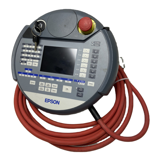
Functions & Installation 2. Specifications 2. Specifications 2.1 Part Names and Functions Front view Back view TP1 Rev.5... - Page 20 Teach Pendant is operated in TEACH mode. The switch turns ON when it is at the midpoint, and it turns OFF when it is fully gripped or released. (7) Handle Use this part as the hand strap while operating the Teach Pendant. TP1 Rev.5...
-
Page 21: Standard Specifications
Electrical characteristics specifications 2.3 Outer Dimensions NOTE Use the installation metal in the attachment when attaching the Teach Pendant to a panel, or the like. TP1 Rev.5 Functions & Installation 2. Specifications Item DC24 V 6 W or less 1075 g... -
Page 22: Installation
Functions & Installation 3. Installation 3. Installation 3.1 Contents TP1 (with cables) Mode selector key 3.2 Environmental Conditions The Teach Pendant must be used in an environment that conforms to the following requirements to ensure safe and reliable operation. Item... -
Page 23: Connection
Controller B: Only using Teach Pendant (TP Cable B) Controller C: Only using Operator Panel Controller D: Using Teach Pendant and Operator Panel Controller TP1 Rev.5 Functions & Installation 3. Installation TP Cable Teach Pendant Conversion Kit CK1 Teach TP Cable... -
Page 24: Connection To The Controller
Operator Panel, both Operator Panel and Teach Pendant are available. (Connection D) NOTE Do not connect TP1 to the following Robot Controllers. following Robot Controllers may result in malfunction of the device since the pin assignments are different. RC420 / RC520 / SRC5** / SRC-3** / SRC-2** 3.4.2 Connection to the Controller... -
Page 25: Power Supply
The power of the Teach Pendant is supplied via the TP/OP connector on the Controller. After the completing the Controller and the Teach Pendant communication, the following screen will appear on the display of the Teach Pendant. TEACH mode AUTO mode TP1 Rev.5... -
Page 26: Wall Bracket (Option)
Functions & Installation 3. Installation 3.6 Wall Bracket (Option) Outer Dimension [Unit :mm] 201.4 56.2 Detail : J Detail : K Front View Hook A 39.6 Hook B Back View Side View TP1 Rev.5... - Page 27 (1) Secure the wall bracket to the wall with three screws (positions are indicated by dotted line in the Outer Dimension). (2) Hang the handle of the Teach Pendant to Hook A. (3) Hang the cable of the Teach Pendant to Hook B. Teach Pendant Cable TP1 Rev.5...
-
Page 28: Operation Mode (Teach/Auto)
Jog Distance data 2.4 Arm / Tool / Local / ECP 2.5 Executing I/O Commands 2.2 Editing Points 2.6 Executing Motion Commands 2.7 Calibration (E2 series / G series) 2.8 Calibration (PS series) 2.9 Releasing the Brake (PS3 only) TP1 Rev.5... -
Page 29: Switch Operation Mode
Change the TEACH mode and AUTO mode with the mode selector key switch on the Teach Pendant. TEACH mode AUTO mode TP1 Rev.5 Functions & Installation 4. Operation Mode (TEACH/AUTO) Turn the mode selector key switch to “Teach” for TEACH mode. Pauses the executing program when operation mode is switched to TEACH mode. -
Page 30: Operation Panel (Key Description)
SP (space) Common Enter E-STOP lamp Safety lamp Jog keys Reset key Motor key Home key OK key Function keys Function Number input Alphabet input Space input Case selector Symbol input Clear number and alphabet Set number and alphabet TP1 Rev.5... - Page 31 Example : Press the <F3> key to display the Motion screen. NOTE When a function key is not assigned to a screen, the key is invalid. Example : <F7> TP1 Rev.5 Functions & Installation 5. Operation Panel (Key Description) Mode +1 the value ↑...
- Page 32 Save the setting and move on to the next screen Set the initial setup status Switch the motor power ON/OFF Move the robot to home position Function Turns ON when the EMERGENCY STOP switch is pressed Turns ON when the safeguard is open TP1 Rev.5...
-
Page 33: Enable Switch
Enable Switch (for Right Hand) Right side view Back view Left side view How to press the Enable switch Grip the enable switch by the finger on the hand holding the handler. Example : When gripping by the left hand Handle TP1 Rev.5... - Page 34 Functions & Installation 6. Enable Switch TP1 Rev.5...
-
Page 35: Operation
Operation This section contains information about operation of the Teach Pendant and maintenance procedure. -
Page 37: Teaching Procedure
In Continuous Jog, moves the Robot while pressing the Jog key. Press the <Jog Dist> key to select “Cont Jog” for the [Jog Dist]. Execute the continuous jog by gripping the enable switch as pressing the Jog key. TP1 Rev.5 Operation 1. Teaching Procedure... -
Page 38: Teaching
(4) Press the <OK> key to assign the robot position. (5) Press the <Save Points> key to display the following screen. Enter the file name and press the <Enter> key. (6) Press the <OK> key to save the file. TP1 Rev.5... -
Page 39: Direct Teaching
(4) Press the <Teach> key. (5) The following screen appears. When the point number is already used, the following screen appears. (6) Press the <OK> key to assign the robot position. TP1 Rev.5 Operation 1. Teaching Procedure : Lock : Servo OFF the joint... - Page 40 Operation 1. Teaching Procedure (7) Press the <Save Points> key to display the following screen. Enter the file name and press the <Enter> key. (8) Press the <OK> key to save the file. TP1 Rev.5...
-
Page 41: Teach Mode
2.1 Jog & Teach Maintenance NOTE A coordinate point including the arm pose is defined as “position (point),” and the data is called “point data.” TP1 Rev.5 Point Editor 2.2 Editing Points Edit Distance 2.3 Changing the Jog Distance Data Arm/Tool/Local/ECP 2.4 Arm / Tool / Local / ECP... -
Page 42: Jog & Teach]
A separate set of jog buttons will appear when using joint mode when using non-Cartesian robots. : Jogs the robot along the axes of the coordinate system defined by the current external control point. Coordinates are World coordinates. TP1 Rev.5... -
Page 43: Specifying Jog Speed
Set On/Off for each joint. <+> key <−> key <F2> key : All Lock : Sets all joints to Off. <F3> key : All Free TP1 Rev.5 : Low jog speed : High jog speed : Long jog distance : Short jog distance : Lock : Sets the joint to Off. -
Page 44: Motor On/Off
(2) The following screen appears. When the point number is already used, the following screen appears. (3) Press the <OK> key to assign the point data. (4) Press the <Save Points> key. This can also be executed in the [Point Editor] screen. TP1 Rev.5... -
Page 45: Saving Point Data To File
(2) The following screen appears. Move the cursor to select a file. (3) Press the <OK> key to load the point data in the file memory. This can also be executed in the [Point Editor] screen. TP1 Rev.5 Operation 2. TEACH Mode... -
Page 46: Editing Points
(2) Move the cursor to each joint, and set the coordinate data/pose flag. (3) Press the <Enter> key. (4) Press the <OK> key to apply the memory. 2.2.4 Deleting Point Data Press the <F3> key to delete the point data. TP1 Rev.5... -
Page 47: Changing Jog Distance Data
Medium, Short) that is to be changed. (2) Move the cursor to each joint, and set the value. 2.3.2 Return Data to Defaults Press the <F1> key to return jog distance data to their defaults. TP1 Rev.5 Operation 2. TEACH Mode... -
Page 48: Arm/Tool/Local/Ecp
2.4.3 Changing Local No. (1) Press the <F3> key and move the cursor to [Local]. (2) Set the local number. 2.4.4 Changing ECP No. (1) Press the <F4> key and move the cursor to [ECP]. (2) Set the ECP No. TP1 Rev.5... -
Page 49: Executing I/O Commands
(1) Press the <F3> key to display the “Outputs” status. (2) Move the cursor to the output bit that you want to change. (3) Switch the ON/OFF status of the output bit. <F1> key: On <F2> key: Off TP1 Rev.5 Operation 2. TEACH Mode... -
Page 50: Executing Motion Commands
Move the cursor to the desired motion command, and press the <OK> key. (2) The motion command screen appears. Set the information required for the command, and press the <Enter> key to apply the settings. (3) Press the <OK> key to execute the command. TP1 Rev.5... -
Page 51: Calibrating Origin : E2 Series / G Series
The following screen appears when the password is set up. NOTE Enter the password (1 to 16 characters) and press the <OK> key. For password setting, refer to Operation 4. Password Setup. (3) The following calibration menu screen appears. TP1 Rev.5 Operation 2. TEACH Mode... -
Page 52: Calibration Procedures (E2 Series)
Joint #4 alone because of the structure of the Manipulator. (1) In the [Calibration] screen, move the cursor to “0 Joint #1-4”, and press the <OK> key. (2) The following screen appears. Press the <F2> key. (3) The following screen appears. TP1 Rev.5... - Page 53 (4) When a message appears regarding the capacitor charge, leave the power ON for 3 or more minutes to sufficiently charge the capacitor. Press the <F2> key to display the following screen. (5) The following screen appears. TP1 Rev.5 Operation 2. TEACH Mode...
- Page 54 0 pulse position of Joint #4 : position where the flat surface on the shaft faces toward system 0 pulse (Regardless of the Joint #1 direction) 0 pulse Upper limit: 0 pulse the tip of Arm #2 0 pulse TP1 Rev.5...
- Page 55 ON position. Sensor monitor DIP switch (SD1) (10) Press and hold the reset switch (SW1) for 1 or more seconds. (11) Press the <F2> key to display the following screen. TP1 Rev.5 Acrylic Panel Reset switch (SW1) Operation 2. TEACH Mode...
- Page 56 One revolution of the Joint #1 motor: ± 4.5 degrees One revolution of the Joint #2 motor: ± 7.2 degrees One revolution of the Joint #3 motor: ± 13.4 mm One revolution of the Joint #4 motor: ± 22.5 degrees Acrylic Panel TP1 Rev.5...
- Page 57 Press the <F2> key to display the following screen. (17) The following screen appears. Manually move and position the joint that needs origin alignment while pushing the Joint #3 brake release button and lowering Joint #3. Press the <F2> key. TP1 Rev.5 Operation 2. TEACH Mode...
- Page 58 Move the joints except the calibrated joints to the point data position by the motion command. For an example the motion command will be executed to Joint #1 and #2 when Joint #4 is calibrated. Press the <OK> key while gripping the enable switch to execute Go P1. TP1 Rev.5...
- Page 59 Set the calibrated joints to the selected point data position accurately by the jog motion. Press the Jog key to move the joint to the basic pose as accurate as possible. Press the <F2> key. (21) The following screen appears. Press the <F1> key. TP1 Rev.5 Operation 2. TEACH Mode...
-
Page 60: Calibration Procedures (G Series)
Joint #4 alone because of the structure of the Manipulator. (1) In the [Calibration] screen, move the cursor to “0 Joint #1-4”, and press the <OK> key. (2) The following screen appears. Press the <F2> key. TP1 Rev.5... - Page 61 <F2> key. <→> key : Joint selection <←> key : Joint selection reset The following screen appears when selection Joint #4 and Joint #3 is selected automatically. (4) The following screen appears. TP1 Rev.5 Operation 2. TEACH Mode...
- Page 62 0 pulse position of Joint #4 : position where the flat surface on the shaft faces toward system 0 pulse (Regardless of the Joint #1 direction) 0 pulse Upper limit: 0 pulse the tip of Arm #2 0 pulse TP1 Rev.5...
- Page 63 One revolution of the Joint #3 motor: Z180 : ± 11.94 mm One revolution of the Joint #4 motor: ± 24.06 degrees (8) The following screen appears. Press the <Motor> key to turn ON the motor. Press the <F2> key. TP1 Rev.5 Operation 2. TEACH Mode Z330 : ± 23.87 mm...
- Page 64 (10) The following screen appears. Manually move and position the joint that needs origin alignment while pushing the Joint #3 brake release button and lowering Joint #3. Press the <F2> key. (11) The following screen appears. Press the <F1> key to execute temporary calibration. TP1 Rev.5...
- Page 65 For an example the motion command will be executed to Joint #1 and #2 when Joint #4 is calibrated. Press the <OK> key while gripping the enable switch to execute Go P1. The following screen appears during Go P1 execution. TP1 Rev.5 Operation 2. TEACH Mode...
- Page 66 Press the Jog key to move the joint to the basic pose as accurate as possible. Press the <F2> key. (14) The following screen appears. Press the <F1> key. (15) The origin calibration completed screen appears. NOTE For righty or lefty setting, refer to 2.7.3 Setting Righty / Lefty. TP1 Rev.5...
-
Page 67: Setting Righty / Lefty (E2 Series / G Series)
<↑> and <↓> keys and press the <Enter> key. Press the <F2>key. (3) The following screen appears. Press the <Motor> key to turn ON the motor. Press the <F2> key. TP1 Rev.5 Operation 2. TEACH Mode... - Page 68 (5) The following screen appears after Jump P1 execution. Press the <F2> key. (6) The following screen appears. Switch the arm orientation between right and left and move to the same point. Press the <OK> key while gripping the enable switch to execute Jump P1. TP1 Rev.5...
- Page 69 (7) The following screen appears after executing Jump P1. Set the calibrated joints to the basic pose accurately by the jog key. Press the <F2> key. (8) The following screen appears. Press the <F1> key. (9) The origin calibration completed screen appears. TP1 Rev.5 Operation 2. TEACH Mode...
-
Page 70: Calibrating Origin : Ps Series
The following screen appears when the password is set up. Enter the password (1 to 16 characters) and press the <OK> key. For password setting, refer to Operation 4. Password Setup. (3) The following screen appears. Press the <F2> key. TP1 Rev.5... - Page 71 <→> key : Joint selection <←> key : Joint selection reset The following screen appears when selecting Joint #5 and Joint #6 is selected automatically. (5) The following screen appears. Press the <F2> key. TP1 Rev.5 Operation 2. TEACH Mode...
- Page 72 When the joint does not move to 0 pulse, move the joint to the set basic pose marked in Setup & Operation Setting the Basic Pose for Calibration in the Manipulator manual. Press the <F2> key. (8) The following screen appears. Press the <F2> key. TP1 Rev.5...
- Page 73 Press the <Motor> key to turn ON the motor. Press the <F2> key. (11) The following screen appears. Press the Jog key to move the joint to the basic pose as accurate as possible. Press the <F2> key. TP1 Rev.5 Operation 2. TEACH Mode...
- Page 74 For an example the motion command will be executed to Joint #1 to #4 when Joint #5 is calibrated. Press the <OK> key while gripping the enable switch to execute Go P0. The following screen appears during Go P0 execution. TP1 Rev.5...
- Page 75 Press the Jog key to move the joint to the basic pose as accurate as possible. Press the <F2> key. (15) The following screen appears. Press the <F1> key. (16) The origin calibration completed screen appears. TP1 Rev.5 Operation 2. TEACH Mode...
-
Page 76: Releasing Brake (Ps Series Only)
Move the cursor to “1 Brake” and press the <OK> key. The following screen appears when the password is set up. Enter the password (1 to 16 characters) and press the <OK> key. For password setting, refer to Operation 4. Password Setup. (3) The following screen appears. TP1 Rev.5... - Page 77 (4) Press the <Jog-> key of the joint whose brake On/Off setting is to be switched. (5) The brake Off confirmation message appears. Confirm the message and press the <F1> key. (6) The brake is released, and the specified joint moves manually. TP1 Rev.5 Operation 2. TEACH Mode...
-
Page 78: Auto Mode
3.6.8 Restoring the System 3.6.9 Changing Speed 3.6.10 Configuration Program editor execution 3.6.11 Changing the Display 3.6.12 Updating the System 3.7 Backup/Restore 3.8 Saving Controller Statuses 3.9 Displaying Date and Time 3.10 Adjusting Brightness and 3.11 Error Messages TP1 Rev.5... - Page 79 <F4> key to display the [Main Menu] screen. Menus with “...” at the end have following procedures after selecting the menu and cannot be executed only by pressing the <OK> key. TP1 Rev.5...
-
Page 80: Program Command Display
When a message appears and a response is requested Program Example : PRINT #24,“Test Print” INPUT #24,a$ Input the response to the message at the cursor position. (Characters or numerical values) <F1> Deletes all entered characters or numerical values. <F4> The [Main Menu] screen appears. TP1 Rev.5... -
Page 81: I/O Monitor
In the [Main Menu] screen, move the cursor to [2 Memory I/O Monitor], and press the <OK> key. Memory I/O status (bit units) <F2> Switches the I/O bit status display (Bit units or port units). TP1 Rev.5 Operation 3. AUTO Mode... -
Page 82: Task Monitor
When the task is “NoEmgAbort task”, “*E” is attached at the end of the task name. <F1> Displays the line number and task name in the program specified by the cursor. <F2> Displays the status and line number of all tasks in the program specified by the cursor. TP1 Rev.5... -
Page 83: System History
In the [Main Menu] screen, move the cursor to [4 System History], and press the <OK> key. Displays the item type, Number, joint #, task #, date, and time in this order from the left. [System History] main screen <F2> Displays the details of the error specified by the cursor. TP1 Rev.5... -
Page 84: Program Mode
<OK> key. When a password is set up, the following screen appears before displaying the [Program Mode] screen. Enter the password (1 to 16 characters). Press the <OK> key. For password setting, refer to Operation 4. Password Setup. TP1 Rev.5... -
Page 85: Open Programs
Select the “function” and press the <OK> key to open the file. When there are two or more files Select the file, and press the <OK> key to open the file. (2) The following screen appears. Program edit screen (example) TP1 Rev.5 Operation 3. AUTO Mode... - Page 86 SP (space) Character input mode Common Enter <Alph/Num> key <CLR> key <Enter> key Function Numerical value input Character input Space input Switching between lowercase and uppercase Symbol input Clears numerical values and text. Determines numerical values and characters. TP1 Rev.5...
- Page 87 If you enter a space ( ) , . = > following a specific command statement, such as “MOTOR” or “POWER”, candidate characters to enter appear. Move the cursor, select the desired character, and press the <Enter> key. TP1 Rev.5 Operation 3. AUTO Mode...
- Page 88 The following screen appears when the program file has been changed but not saved. <F1> Saves the file, and returns to the program edit screen. <F2> Returns to the [Program Mode] screen without saving the changes of the program file. TP1 Rev.5...
- Page 89 If the character string is not found, the cursor position does not change. Jump This section describes settings that can be made in the [Go to] screen. In the program edit screen, press the <F4> key. The following screen appears. TP1 Rev.5 Operation 3. AUTO Mode...
- Page 90 (1) Move the cursor to [Function], and press the <Enter> key. (2) The following screen appears. Move the cursor to the desired “function” and press the <OK> key. The following screen appears during execution. (3) The specified “function” screen appears. TP1 Rev.5...
-
Page 91: Building Projects
The error message list appears. Move the cursor to the desired error, and press the <OK> key. The file with the error appears, and the error line is indicated by the cursor. TP1 Rev.5 Building of the project is started. Operation 3. AUTO Mode... -
Page 92: Backing Up Projects
Press the <OK> key to execute the project backup. Saves the project to the folder “\EpsonRC50\Projects” in the USB memory. When a project of the same name exists in the USB memory, the following screen appears. <OK> Overwrites the project. <Cancel> Cancels the project backup. TP1 Rev.5... -
Page 93: Restore Projects
Displays the project list in the folder “\EpsonRC50\Projects” in the USB memory. Move the cursor to the desired project, and press the <OK> key. (5) The following screen appears. Press the <F1> key. (6) Executes the project restore. TP1 Rev.5 Operation 3. AUTO Mode... -
Page 94: Import Files
Displays the hierarchy one level above the selected folder. (4) Executes the file import. When a file of the same name already exists, the following screen appears. <F1> Overwrites the file. <F2> Moves to the [Program Mode] screen. TP1 Rev.5... -
Page 95: Export Files
(5) The following screen appears. Move the cursor to export and press the <OK> key. <Enter> Displays the hierarchy one level below the selected folder. <F1> Displays the hierarchy one level above the selected folder. TP1 Rev.5 Operation 3. AUTO Mode... - Page 96 (6) The following screen appears. Press the <OK> key. (7) Executes the file export. When a file of the same name already exists, the following screen appears. <F1> Overwrites the file. <F2> Moves to the [Program Mode] screen. TP1 Rev.5...
-
Page 97: Backup System
USB memory. For procedure to specify the folder, refer to (5). (5) The following screen appears. Move the cursor to the folder to save the backup data and press the <OK> key. TP1 Rev.5 Operation 3. AUTO Mode... - Page 98 (6) The following screen appears. Press the <OK> key to execute the system backup. When a file of the same name already exists, the following screen appears. <F1> Overwrites the file. <F2> Moves to the [Program Mode] screen. (7) After execution is completed, the following screen appears TP1 Rev.5...
-
Page 99: Restore System
[Project] and press the <→> key. (4) Press the <OK> key (5) The following screen appears. Press the <OK> key. (6) The following screen appears. Move the cursor to the desired folder. Press the <Enter> key. TP1 Rev.5 Operation 3. AUTO Mode... - Page 100 When the Controller system software version does not match the version of the selected Controller setting data, the following screen appears. To continue, press the <F1> key. (8) After execution is completed, the following screen appears. Press the <OK> key and the Controller reboots. TP1 Rev.5...
-
Page 101: Changing Speed Factor
Returns the factor to its default (100). (3) Press the <OK> key to set the value. 3.6.10 Configuration In the [Program Mode] screen, move the cursor to [9 Configuration...], and press the <OK> key. The following screen appears. TP1 Rev.5 Operation 3. AUTO Mode... - Page 102 Press the <OK> key and the Controller reboots. To change an item: Move the cursor to the left column. To change item settings: Move the cursor to the right column. : Set the area to the entire file. TP1 Rev.5...
-
Page 103: Change Display Language
(1) In the [Program Mode] screen, move the cursor to the last line, and press the <↓> key. The following screen appears. Move the cursor to [0 Language...] and press the <OK> key. TP1 Rev.5 Operation 3. AUTO Mode To change an item: Move the cursor to the left column. -
Page 104: Update System Software
(2) In the [Program Mode] screen, move the cursor to the last line, and press the <↓> key. The following screen appears. Move the cursor to [1 Update System Software], and press the <OK> key. (3) The following screen appears. Press the <OK> key. TP1 Rev.5... - Page 105 <Enter> Displays the hierarchy one level below the selected folder. <F1> Displays the hierarchy one level above the selected folder. (5) The following screen appears. Press the <F1> key to execute the update. (6) After the software is updated, the following screen appears. TP1 Rev.5 Operation 3. AUTO Mode...
-
Page 106: Backup / Restore
Project backup ... Operation 3.6.3 Backup Projects Restoring projects ... Operation 3.6.4 Restore Projects Importing files ... Operation 3.6.5 Import Files File export... Operation 3.6.6 Export Files System backup ... Operation 3.6.7 Backup System System restore... Operation 3.6.8 Restore System TP1 Rev.5... -
Page 107: Save Controller Statuses
(1) In the [Main Menu] screen, move the cursor to [8 Date / Time], and press the <OK> key. (2) The following screen appears. Able to check the date and time. <F1> Returns to the [Main Menu] screen. TP1 Rev.5 Operation 3. AUTO Mode... -
Page 108: Adjust Brightness And Contrast
These arrow keys can adjust the brightness. <←><→> These arrow keys can adjust the contrast. 3.11 Error Messages The following screen appears when an error occurs. <F4> Moves to the [Main Menu]. <OK> Moves to the screen before the error occurred. TP1 Rev.5... -
Page 109: Password Setup
AUTO mode ... [Main Menu]-[Program Mode...] Follow the procedure below to set the password. (1) Turn ON the Controller. (2) Double click the <EPSON RC+ 5.0> icon on the desktop. (3) Select EPSON RC+5.0 menu-[Setup]-[Controller]-[Configuration] to display the following page. -
Page 110: Troubleshooting
- Send the latch release input signal to release the latch status. If the condition does not change after performing the countermeasure above, the unit may have suffered a breakdown. Please contact the service center or the manufacturer. TP1 Rev.5... -
Page 111: Maintenance Parts List And Option
6. Maintenance Parts List and Option Be sure to specify the proper codes and Option when ordering maintenance parts. Part Name TP1 (with cables) Wall Bracket Conversion Kit TP1 Rev.5 Operation 6. Maintenance Parts List and Option Code Type A... - Page 112 Operation 6. Maintenance Parts List and Option TP1 Rev.5...