Table of Contents
Advertisement
Quick Links
Advertisement
Table of Contents

Related Manuals for Epson TP1

Summary of Contents for Epson TP1
- Page 1 Robot Controller Option Teach Pendant Rev.8 EM216P4625F...
- Page 3 Robot Controller Option Teach Pendant Rev.8 Copyright © 2012-2021 SEIKO EPSON CORPORATION. All rights reserved. TP1 Rev.8...
- Page 4 Please notify us if you should find any errors in this manual or if you have any comments regarding its contents. MANUFACTURER CONTACT INFORMATION Contact information is described in “SUPPLIERS” in the first pages of the following manual: Robot System Read this manual first Safety Manual TP1 Rev.8...
- Page 5 Robot system. The “TIP” sections describe hints for easier or alternative operations. When using RC700 / RC90 option TP1 with the Robot Controller RC180, RC170, or RC620, NOTE refer to the following manuals. When connecting TP1 to RC180 / RC170 robot controllers:...
- Page 6 RC90 controller firmware Ver.7.0.2.0 Before Ver.7.0.1 EPSON RC+ 7.0 Ver.7.0.2 or later OK: Compatible All functions of the EPSON RC+ 7.0 and the Controller are available. !!!: Compatible Connection is OK. We recommend using EPSON RC+7.0 Ver. 7.0.2 or later. NOTE ...
-
Page 7: Table Of Contents
3.6 Power Supply ....................18 4. Operation Mode (TEACH, AUTO, TEST) 4.1 Outline ......................19 4.2 Switching Operation Mode ................21 5. Operation Panel (Key Description) 5.1 Key Description .................... 22 6. Enable Switch 7. Warning Sound (Beep) TP1 Rev.8... - Page 8 2.6.1 Changing Jog Distance ..............45 2.6.2 Default ..................... 45 2.7 Point Editor ....................46 2.7.1 Specifying Point Number ..............46 2.7.2 Changing Point Label ..............46 2.7.3 Changing Coordinate Data and Pose Flag ........47 2.7.4 Deleting Point Data ................. 47 TP1 Rev.8...
- Page 9 4.6.6 Walk ....................70 4.6.7 Run Window (TEST mode) .............70 4.6.8 I/O monitor (TEST mode) ..............71 4.6.9 Variables (TEST mode) ..............72 4.6.10 Task Manager (TEST mode) ............72 4.7 Error ......................73 5. Password Setup 6. Troubleshooting 7. Maintenance Parts List TP1 Rev.8...
- Page 10 Table of Contents 8. Option Parts List viii TP1 Rev.8...
-
Page 11: Functions & Installation
Functions & Installation This section contains information about functions and installation of the Teach Pendant to be known before operation and maintenance. -
Page 13: Safety
The personnel who have completed the robot system-training class held by the manufacturer, dealer, or locally-incorporated company are allowed to maintain the robot system. Only personnel who has taken maintenance training held by us and suppliers should be allowed to perform the maintenance of robot system. TP1 Rev.8... - Page 14 Damaged cables, disconnection, or contact failure is extremely WARNING hazardous and may result in electric shock and/or improper function of the system. Do not use the cables near heat or fire. TP1 Rev.8...
- Page 15 Safety of machinery -- Electrical equipment of machines -- Part 1: General requirements IEC 60204-1 Industrial, scientific and medical (ISM) radio-frequency equipment -- Electromagnetic CISPR11 disturbance characteristics -- Limits and methods of measurement Electromagnetic compatibility (EMC) -- Part 6-2: Generic standards -- Immunity for IEC 61000-6-2 industrial environments TP1 Rev.8...
-
Page 16: Emergency Stop
(3) Turn the Teach Pendant mode selector key switch to “Teach”. (4) Press the <Reset> key on the operation panel to reset the Emergency Stop. (5) Make sure that the E-Stop lamp on the operation panel is OFF. E-STOP lamp <Reset> key TP1 Rev.8... -
Page 17: Mode Selector Key Switch
Function key F1: Test Mode. Mode switching during task execution AUTO → TEACH (1) Press the <Stop> button of EPSON RC+ to stop all tasks normally. (2) Turn the mode selector key switch to “Teach”. TEACH → AUTO Turn the mode selector key switch to “Auto” and close the latch release input. -
Page 18: Using Teach Pendant In Safeguarded Area
To switch the mode from TEACH to AUTO, release the latched condition using the latch release input. Although the Teach Pendant can be operated inside the safeguarded area as described above, operate the robot system while all operators are outside of the safeguarded area wherever CAUTION possible. TP1 Rev.8... -
Page 19: Specifications
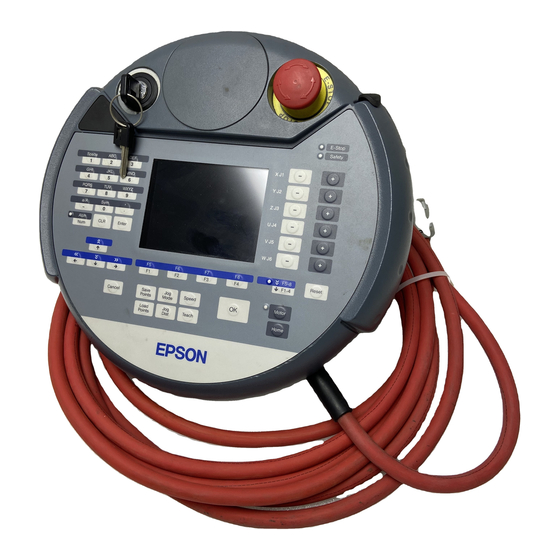
Functions & Installation 2. Specifications 2. Specifications 2.1 Part Names and Functions Front view Back view TP1 Rev.8... - Page 20 Teach Pendant is operated in TEACH mode. The switch turns ON when it is at the midpoint, and it turns OFF when it is fully gripped or released. (7) Handle Use this part as the hand strap while operating the Teach Pendant. TP1 Rev.8...
-
Page 21: Standard Specifications
LED (Color : White) Serial interface Electrical characteristics Compliant with RS-422A standard specifications 2.3 Outer Dimensions 8° 251.9 (Unit : mm) NOTE Use the installation metal in the attachment when attaching the Teach Pendant to a panel, or the like. TP1 Rev.8... -
Page 22: Installation
Functions & Installation 3. Installation 3. Installation 3.1 Contents TP1 (with cables) : 1 unit Mode selector key : 2 units 3.2 Environmental Conditions The Teach Pendant must be used in an environment that conforms to the following requirements to ensure safe and reliable operation. -
Page 23: Wall Bracket (Option)
Functions & Installation 3. Installation 3.4 Wall Bracket (Option) 3.4.1 Outer Dimension [Unit :mm] 201.4 56.2 Detail : J Detail : K Front View Hook A 39.6 Hook B Back View Side View TP1 Rev.8... -
Page 24: Mount And Use
(1) Secure the wall bracket to the wall with three screws (positions are indicated by dotted line in the Outer Dimension). (2) Hang the handle of the Teach Pendant to Hook A. (3) Hang the cable of the Teach Pendant to Hook B. Teach Pendant Cable TP1 Rev.8... -
Page 25: Connection
When connecting the connector, note that the waterproof efficiency and dustproof efficiency of the connector do not comply with IP65. When connecting the Teach Pendant TP1 to the TP port, be careful of the connector inserting direction (up/down). -
Page 26: Typical Cable Connection
TP Cable A : Direct connection is available with conversion kit CK1. TP Cable B : D-sub connector to connect directly to the Controller. - When connecting TP1 to RC700-A, the RC700-A conversion cable is necessary. If you need the conversion cable, please contact the supplier of your region. -
Page 27: Connection To The Controller
Functions & Installation 3. Installation - Operation of RC700 / RC90 option TP1 differs from the descriptions in this manual when it is connected to the Robot Controllers RC180, RC170, or RC620. In this case, refer to the following manuals. -
Page 28: Power Supply
The power of the Teach Pendant is supplied via the TP connector on the Controller. After completing the Controller and the Teach Pendant communication, the following screen will appear on the display of the Teach Pendant. TEACH mode AUTO mode TP1 Rev.8... -
Page 29: Operation Mode (Teach, Auto, Test)
This mode can operate the specified Function with multi-task / single- task, multi-manipulator / single-manipulator at low speed. NOTE This product does not support a high-speed program verification function (T2: manual acceleration mode) defined in Safety Standards. TP1 Rev.8... - Page 30 3.4 Task Monitor System History 3.5 System History Speed Factor 3.6 Speed Factor Date / Time 3.7 Data / Time Brightness / Contrast 3.8 Brightness / Contrast Language 3.9 Language Error 3.10 Error NAME : Screen name : Reference section TP1 Rev.8...
-
Page 31: Switching Operation Mode
If the mode is switched with the mode switching key switch while the enable switch is turned ON, and the motor is turned ON, an error will occur. Be sure to turn the enable switch OFF once and then ON again before turning the motor ON. TP1 Rev.8... -
Page 32: Operation Panel (Key Description)
From 0 to 9 Number input Number input mode - (minus) .(period) ABC to WXYZ Alphabet input SP (space) Space input Alphabet input mode Case selector Symbol input Clear number and alphabet Common Enter Set number and alphabet TP1 Rev.8... - Page 33 Press the <F5-8> key to turn ON/OFF the “F5-8” lamp. The display changes. Example : Jog&Teach Screen “F5-8” OFF “F5-8” ON Example: Press the <F3> key to display the Motion screen. NOTE When a function key is not assigned to a screen, the key is invalid. Example: <F7> TP1 Rev.8...
- Page 34 Move the robot to home position * Keys with this mark are available only in TEACH mode. Lamp Lamp Function E-Stop Turns ON when the EMERGENCY STOP switch is pressed Safety Turns ON when the safeguard is open TP1 Rev.8...
-
Page 35: Enable Switch
How to press the Enable switch Grip the enable switch by the finger on the hand holding the handler. Example : When gripping by the left hand Handle 7. Warning Sound (Beep) The Teach Pendant beeps when the robot passes the singularity. TP1 Rev.8... - Page 36 Functions & Installation 6. Enable Switch TP1 Rev.8...
-
Page 37: Operation
Operation This section contains information about operation of the Teach Pendant and maintenance procedure. -
Page 39: Teaching Procedure
The continuous jog can be executed by gripping the enable switch as pressing the Jog key. NOTE To execute the continuous jog, press some jog keys at a time. For example, press the <+X> and <+Y> keys together for the continuous jog diagonally. TP1 Rev.8... -
Page 40: Teaching
(4) Press the <Save Points> key to display the following screen. (5) Press the <OK> key to save the file. NOTE Press the <Cancel> key to returns to the [Jog & Teach] screen without saving the changes of the file. TP1 Rev.8... -
Page 41: Direct Teaching
(5) Move the Robot arm to the position to teach. (6) Press the <Teach> key, the following screen appears. When the point number is already used, the following screen appears. (7) Press the <OK> key to assign the robot position. TP1 Rev.8... - Page 42 (8) Press the <Save Points> key to display the following screen. Press the <OK> key to save the file. NOTE Press the <Cancel> key to returns to the [Jog & Teach] screen without saving the changes of the file. TP1 Rev.8...
-
Page 43: Teach Mode
2.8 Brake Brake (For 6-axis robot) F1-F8 : Function key Name : Screen name : Reference section NOTE A coordinate point including the arm pose is defined as “position (point),” and the data is called “point data.” TP1 Rev.8... -
Page 44: Jog & Teach
ECP : Jogs the robot along the axes of the coordinate system defined by the current external control point. Coordinates are World coordinates. NOTE When the <F5-8> key lights up its LED, the toggle of <Jog Mode> key is the opposite direction. TP1 Rev.8... -
Page 45: Specifying Jog Speed
When the additional S axis is set on the 6-axis robot, the key display is changed as shown below to move the additional S axis. When the Jog keys are not displayed, the robot cannot move by pressing keys. TP1 Rev.8... -
Page 46: Executing Step Jog
: Sets the joint to Off. <+> key : Lock : Sets the joint to On. <F3> key : Free All : Sets all joints to Off. <F4> key : Lock All : Sets all joints to On. TP1 Rev.8... -
Page 47: Motor On/Off
ON again before turning the motor ON. This can be executed at any time in TEACH mode. 2.1.9 Executing Return to Home Press the <Home> key to return the robot to its home position. TP1 Rev.8... -
Page 48: Teaching
When the point number is already used, the following screen appears. (2) Press the <OK> key to assign the point data. (3) Press the <Save Points> key. This can also be executed in the [Point Editor] screen. TP1 Rev.8... -
Page 49: Saving Point File
Operation 2. TEACH Mode 2.1.11 Saving Point File (1) Press the <Save Points> key. The following screen appears. (2) Press the <OK> key to save the positions to the file. This can also be executed in the [Point Editor] screen. TP1 Rev.8... -
Page 50: Loading Point File
This is a low speed program verification function (T1: manual deceleration mode) which is defined in Safety Standards. This mode can execute a specified Function with multi- task / single-task, multi-manipulator / single-manipulator at low speed. For details, refer to Operation: 4. TEST mode. TP1 Rev.8... -
Page 51: Robot
Set the robot number first and then change the numbers of Arm, Tool, Local, and ECP. (1) Press the <↑> <↓> keys and move the cursor to item (2) Change the number. (3) Press the <Enter> key. (4) Press the <OK> key to save the settings. TP1 Rev.8... -
Page 52: Motion Command
Set the information required for the motion command, and press the <Enter> key to apply the settings. (3) Press the <OK> key to execute the motion command. NOTE To execute motion command, grip the enable switch while pressing the <OK> key. TP1 Rev.8... -
Page 53: Robots Except 6-Axis Robots
Set the information required for the motion command, and press the <Enter> key to apply the settings. (3) Press the <OK> key to execute the motion command. NOTE To execute motion command, grip the enable switch while pressing the <OK> key. TP1 Rev.8... -
Page 54: I/O Command
(1) Press the <F3> key to display the “Outputs” status. (2) Move the cursor to the output bit that you want to change. (3) Switch the ON/OFF status of the output bit. <F1> key: On <F2> key: Off TP1 Rev.8... -
Page 55: Jog Distance
(1) Press the <↑> <↓> keys and move the cursor to change an item. (2) Change the Jog Distance. (3) Press the <Enter> key. (4) Press the <OK> key to save the settings. 2.6.2 Default Press the <F1> key to return jog distance data to their defaults. TP1 Rev.8... -
Page 56: Point Editor
2.7.2 Changing Point Label (1) Press the <F1> key and move the cursor to [Label]. (2) Enter the label name at [Label] to set the name. (3) Press the <Enter> key. (4) Press the <OK> key to apply the memory. TP1 Rev.8... -
Page 57: Changing Coordinate Data And Pose Flag
To change the orientation flag, point to the orientation flag and press the <F2> key. (3) Press the <OK> key to apply the memory. 2.7.4 Deleting Point Data Press the <F3> key to delete the point data. TP1 Rev.8... -
Page 58: Brake (6-Axis Robots Only)
(1) Press the <F8> key in the [Jog & Teach] screen. The following screen appears. The following screen appears when the password is set up. Enter the password (1 to 16 characters) and press the <OK> key. For password setting, refer to Operation 5. Password Setup. TP1 Rev.8... - Page 59 (3) The brake Off confirmation message appears. Confirm the message and press the <F1> key. The brake is released, and the specified joint moves manually. NOTE For the Jog keys operation, refer to Operation: 2.1.4 Jog key. TP1 Rev.8...
-
Page 60: Auto Mode
3.10 Error NAME : Screen name : Reference section Switch the mode selector key switch to “Auto” to display the [Print] screen. Follow the description on the screen and press the <F4> key to display the [Main Menu] screen. TP1 Rev.8... -
Page 61: Program Command Display
When a message appears and a response is requested Program Example : PRINT #24,“Test Print” INPUT #24,a$ Input the response to the message at the cursor position. (Characters or numerical values) <F1> Deletes all entered characters or numerical values. TP1 Rev.8... -
Page 62: I/O Monitor
In the [Main Menu] screen, move the cursor to [2 Memory I/O Monitor], and press the <OK> key. Displays the item Bit#, Status, and Label in this order from the left. Memory I/O status (bit units) <F2> Switches the I/O status display (Bit units or Byte units). <F4> The [Main Menu] screen appears. TP1 Rev.8... -
Page 63: Task Monitor
When the task name is too long to display the whole name, a tilde is attached at the end of the task name as “LongTaskName_12345˜”. <F1> Displays the status and line number (Six digits) of all tasks in the program specified by the cursor. <F2> Switches the task status display (Back ground task or Normal task). TP1 Rev.8... -
Page 64: System History
In the [Main Menu] screen, move the cursor to [4 System History], and press the <OK> key. Displays the item type, Number, Robot#, Joint #, Task #, Date, and Time in this order from the left. [System History] main screen <F4> The [Main Menu] screen appears. TP1 Rev.8... -
Page 65: Speed Factor
Enter the speed factor to the maximum speed (Unit: %, integer from 1 to 100). Press the <Enter> key to confirm an input. <F1> Returns to the default value (100). (3) Press the <OK> key to set the value. TP1 Rev.8... -
Page 66: Date / Time
<OK> key. (2) Adjust the brightness and contrast. Press the <OK> key to save the status. <↓><↑> These arrow keys can adjust the brightness. <←><→> These arrow keys can adjust the contrast. <F4> Returns to the [Main Menu] screen. TP1 Rev.8... -
Page 67: Language
The new display language setting is enabled after the next startup. <F4> Returns to the [Main Menu] screen. 3.10 Error Error # and Error message appears when an error occurs <OK> Moves to the screen before the error occurred. TP1 Rev.8... -
Page 68: Test Mode
1. Single-task program verification Single task Multi-manipulator 2. Multi-task program verification Multi-task program verification Manual deceleration mode Multi-task Multi-manipulator NOTE This product does not support a high-speed program verification function (T2: manual acceleration mode) defined in Safety Standards. TP1 Rev.8... -
Page 69: Single-Task Program Verification
Before performing program verification, check that the robot system operates normally by using the EPSON RC+ debug function. For details on the EPSON RC+ debug function, refer to the EPSON RC+ User’s Guide 5.10 [Run] Menu. If debugging is insufficient, the robot may cause unintended motion. This is extremely hazardous and may cause serious bodily injury or severe damage to the robot. - Page 70 *1 Xqt task types (NoPause, NoEmgAbort) cannot be executed. If these tasks are specified, they are performed program verification as normal tasks. *2 If background tasks are specified, they are performed program verification as normal tasks. Available Function Functions without parameters Functions with source not hidden TP1 Rev.8...
- Page 71 An error occurs, and the program execution will be aborted. INPUT Input from the console causes an error and aborts the program execution. PRINT #24 Output to the Teach Pendant causes an error and aborts the program execution. TP1 Rev.8...
-
Page 72: Multi-Task Program Verification
Before performing program verification, check that the robot system operates normally by using the EPSON RC+ debug function. For details on the EPSON RC+ debug function, refer to the EPSON RC+ User’s Guide 5.10 [Run] Menu. If debugging is insufficient, the robot may cause unintended motion. This is extremely hazardous and may cause serious bodily injury or severe damage to the robot. - Page 73 Pause Continue Continue the Safety Door Abort Abort Abort Abort Error during a test Abort Abort Continue Abort Emergency stop Abort Abort Abort Continue/Resume Switch to TEACH mode Available Function Functions without parameters Functions with source not hidden TP1 Rev.8...
-
Page 74: Test Mode
Output to the Teach Pendant causes an error and aborts the program execution. 4.3 Test mode This screen is used to select TEST mode. Move the cursor to [Single-task program verification] or [Multi-task program verification], and press the <OK> key. <F4><F8> Returns to [Jog & Teach] screen. TP1 Rev.8... -
Page 75: Function
<F4><F8> Returns to [Jog & Teach] screen. After selecting the project file, the Function list will be displayed in [Selection Function] screen. Move the cursor to the Function to perform program verification and press the <OK> key. <F4><F8> Returns to [Jog & Teach] screen. TP1 Rev.8... -
Page 76: Program List Display
Moves to the left side page <F1> Moves to [Program verification] screen. <F4><F8> Returns to [Jog & Teach] screen. After confirming that the Function to perform program verification is surely selected, press the <F1> key and perform program verification. TP1 Rev.8... -
Page 77: Program Verification
To resume the program, release the latch status of the safeguard interlock. And then, turn on the Enable Switch and push the operation key (Continue, Step In, Step Over, and Walk). The program will resume from the paused position. TP1 Rev.8... - Page 78 <F1> Executes a program in Cycle mode. <F4> Stops program verification. Returns to [Program list display] screen. <F5> Executes a program in STEP mode [Step In] <F6> Executes a program in STEP mode [Step Over] <F7> Executes a program in Walk [Walk]. TP1 Rev.8...
-
Page 79: Multi-Task Program Verification Screen
Executes the current line of the paused task and stops at the next line. If the current line is a function call, the program pauses at the first line of the called function. This key is available in single-task program verification. TP1 Rev.8... -
Page 80: Step Out
In TEST mode, the Run window can be displayed to display Print output data. To display the Run window, select the EPSON RC+- menu-[Run]-[Run window]. Execution, pause, stop, and continue of a program is not available in Run Window (TEST mode). -
Page 81: I/O Monitor (Test Mode)
Operation 4.TEST Mode 4.6.8 I/O monitor (TEST mode) In TEST mode, the EPSON RC+ I/O Monitor dialog can be displayed to monitor I/O status. To display the I/O Monitor dialog, select the EPSON RC+ -menu -[Tools]-[I/O Monitor]. I/O cannot be changed from the I/O Monitor (TEST mode). -
Page 82: Variables (Test Mode)
Variables cannot be changed from the Variables monitor (TEST mode). 4.6.10 Task Manager (TEST mode) In TEST mode, the EPSON RC+ Task Manager dialog can be displayed to monitor the task status. To display the Task Manager dialog, select the EPSON RC+-menu-[Tools]-[Task Manager]. -
Page 83: Error
Operation 4.TEST Mode 4.7 Error When an error occurs, file name, execution line number, error number, and error message will be displayed. <OK> Moves to [Program display] screen. TP1 Rev.8... -
Page 84: Password Setup
Setup a password to limit operators for the brake equipment (6-axis robot only). TEACH mode ..[Jog&Teach]-[Brake] 6-Axis robot only Follow the procedure below to set the password. (1) Select EPSON RC+-menu-[Setup]-[System Configuration]-[SPEL Controller Board]- [Configuration] to display the following screen. (2) Click the <Change> button at “TP Password.”... -
Page 85: Troubleshooting
Robot does not move by pressing the Jog key - Execute the Motor On command to energize the Robot motor. (Refer to Motor On in the EPSON RC+ SPEL+ Language Reference) - Energize the Robot motor. (Refer to SLock in the EPSON RC+ SPEL+ Language Reference) - Short jog distance may be selected. -
Page 86: Maintenance Parts List
8. Option Parts List Part Name Code Old Code Note Wall Bracket R12NZ9005M R12B120105 R12NZ9005N Conversion Kit R12B120111 CK1 TP Exchange Cable 0.5 m R12NZ900L6 Extension Cable R12NZ90111 10 m R12NZ900NJ For RC700-A controller 15 m R12NZ900NK Hot Plug Kit R12N2900NL TP1 Rev.8...