Grizzly G7943 Owner's Manual
12 speed heavy-duty drill press
Hide thumbs
Also See for G7943:
- Owner's manual (52 pages) ,
- Parts manual (4 pages) ,
- Machine data sheet (2 pages)
Table of Contents
Advertisement
MODEL G7943/G7944
12 SPEED HEAVY-DUTY
DRILL PRESS
OwnER'S MAnUAL
G7944
G7943
Copyright © 1992 By grizzly industrial, inC. revised May, 2009 (Bl)
wARnInG: nO PORTIOn Of THIS MAnUAL MAY bE REPRODUcED In AnY SHAPE
OR fORM wITHOUT THE wRITTEn APPROVAL Of GRIzzLY InDUSTRIAL, Inc.
(For Models ManuFaCtured sinCe 10/02) #Bl3698 printed in China
Advertisement
Table of Contents

Related Manuals for Grizzly G7943


Summary of Contents for Grizzly G7943
-
Page 1: Drill Press
OwnER'S MAnUAL G7944 G7943 Copyright © 1992 By grizzly industrial, inC. revised May, 2009 (Bl) wARnInG: nO PORTIOn Of THIS MAnUAL MAY bE REPRODUcED In AnY SHAPE OR fORM wITHOUT THE wRITTEn APPROVAL Of GRIzzLY InDUSTRIAL, Inc. (For Models ManuFaCtured sinCe 10/02) #Bl3698 printed in China... -
Page 3: Table Of Contents
Table of contents InTRODUcTIOn ..........................3 Foreword ............................ 3 Contact info ..........................3 g7943 Machine data sheet ....................... 4 g7944 Machine data sheet ....................... 6 identification ..........................8 SEcTIOn 1: SAfETY ........................9 safety instructions for Machinery ....................9 safety for drill presses......................11 SEcTIOn 2: cIRcUIT REQUIREMEnTS .................. - Page 4 SEcTIOn 7: SERVIcE ........................35 about service ........................... 35 troubleshooting ........................35 depth stop Calibration ......................38 Feed shaft spring tension ...................... 38 SEcTIOn 8: wIRInG ........................40 Wiring safety instructions ......................40 electrical Components ......................41 g7943/g7944 Wiring diagram ....................42 g7943/g7944 parts Breakdown ....................
-
Page 5: Introduction
Web site: http://www.grizzly.com continuous improvement, changes may be made at any time with no obligation on the part of grizzly. For your convenience, we always keep current grizzly manuals available on our website at www. -
Page 6: G7943 Machine Data Sheet
G7943 Machine Data Sheet MACHINE DATA SHEET Customer Service #: (570) 546-9663 · To Order Call: (800) 523-4777 · Fax #: (800) 438-5901 MODEL G7943 12 SPEED HEAVY-DUTY BENCH-TOP DRILL PRESS Product Dimensions: Weight................................142 lbs. Length/Width/Height..........................24 x 14 x 38 in. Foot Print (Length/Width).......................... - Page 7 Other Related Information Base Length............................... 18 in. Base Width..............................11 in. Quill Diameter............................2.040 in. Depth Stop Type.....................Threaded Rod with Positive Stop Column Diameter..........................3.150 in. Illumination........................110V Socket, Separat Spindle Information Spindle Taper.............................MT#2 Spindle Travel............................3-1/4 in. Dist From Spindle To Column........................7 in. Dist From Spindle To Table........................16 in.
-
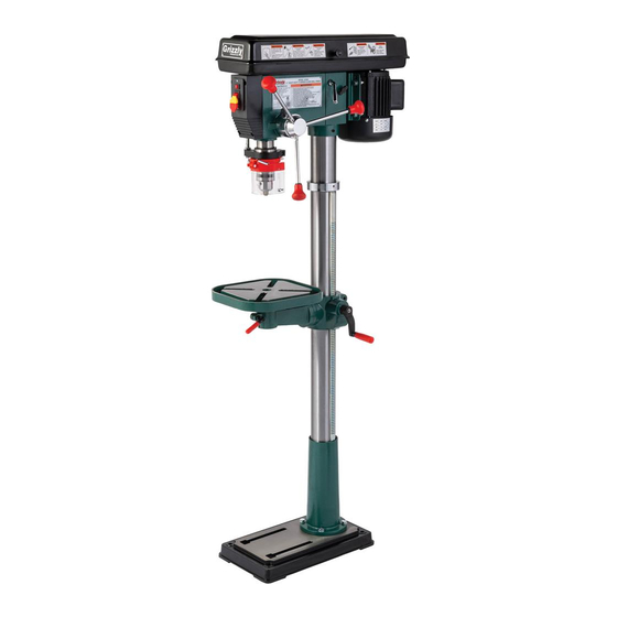
Page 8: G7944 Machine Data Sheet
G7944 Machine Data Sheet MACHINE DATA SHEET Customer Service #: (570) 546-9663 · To Order Call: (800) 523-4777 · Fax #: (800) 438-5901 MODEL G7944 12 SPEED HEAVY-DUTY 14" FLOOR DRILL PRESS Product Dimensions: Weight................................155 lbs. Length/Width/Height..........................24 x 14 x 64 in. Foot Print (Length/Width).......................... - Page 9 Other Related Information Base Length............................... 18 in. Base Width..............................11 in. Quill Diameter............................2.040 in. Depth Stop Type............................Hub Column Diameter..........................3.150 in. Mobile Base..............................G8683 Illumination........................110V Socket, Separat Spindle Information Spindle Taper.............................MT#2 Spindle Travel............................3-1/4 in. Dist From Spindle To Column........................7 in. Dist From Spindle To Table.........................
-
Page 10: Identification
Identification refer to the list below and see figures 1 & 2 to refer to the list below to become familiar with become familiar with the drill press controls. the drill press terms and definitions. Headstock: the cast iron upper portion of the drill Light Switch: turns light ON/OFF. -
Page 11: Section 1: Safety
SEcTIOn 1: SAfETY for Your Own Safety, Read Instruction Manual before Operating this Machine The purpose of safety symbols is to attract your attention to possible hazardous conditions. This manual uses a series of symbols and signal words which are intended to convey the level of importance of the safety messages. - Page 12 Safety Instructions for Machinery 7. OnLY ALLOw TRAInED AnD PROP- 17. REMOVE ADJUSTInG KEYS ERLY SUPERVISED PERSOnnEL TO wREncHES. Make a habit of checking for OPERATE MAcHInERY. Make sure oper- keys and adjusting wrenches before turn- ation instructions are safe and clearly ing machinery ON.
-
Page 13: Safety For Drill Presses
Safety for Drill Presses EYE/fAcE/HAnD PROTEcTIOn. a face DRILL OPERATIOn. never start the drill press with the drill bit pressed against the shield used with safety glasses is rec- ommended. always keep hands and fin- workpiece. Feed the drill bit evenly into the workpiece. -
Page 14: Section 2: Circuit Requirements
SEcTIOn 2: cIRcUIT REQUIREMEnTS 110V Operation Electrocution or fire could result if this machine is not grounded correctly or if your electrical configu- Serious personal injury could occur if you ration does not comply connect the machine to the power source with local and state codes. -
Page 15: Section 3: Set Up
SEcTIOn 3: SET UP Set Up Safety Items needed for Set Up the following items are needed to complete the This machine presents set up process, but are not included with your serious injury hazards machine: to untrained users. Read through this entire manu- Description al to become familiar with... -
Page 16: Inventory
Inventory if any nonproprietary parts are missing (e.g. a nut or a washer), we would be glad to replace them, but for the sake of expediency, you can get replacements at a hardware store. use figure 4 and the inventory list below to inventory your drill press parts: Description table ............ -
Page 17: Hardware Recognition Chart
Hardware Recognition chart -15- Model g7943/g7944 (Mfg. 10/02+) -
Page 18: Clean Up
opti-... -
Page 19: Column And Base
column and base Table Support components and Hardware needed: components and Hardware needed: Base ..............1 table support assembly ........1 Column ...............1 Crank handle ............ 1 hex Bolts M10-1.5 x 25 ........4 handle ............... 1 large lock lever ..........1 the column must be secured on the base to small lock lever .......... - Page 20 Mark the top of the rack, as shown in figure 8, to keep track of which end is up. Column ring Marking location rack figure 10. Correct column ring orientation. install the crank lever over the pinion shaft, figure 8. Marking top of rack to show which end and tighten the setscrew in the crank handle is up.
-
Page 21: Headstock
Headstock suspend a plum bob from the center of the headstock spindle so it is over the tape/ruler as shown in figure 12. components and Hardware needed: Center the headstock directly over the base headstock............1 as indicated by the plum bob and ruler. the headstock must be mounted on the col- umn/base assembly before the drill press can be operated. -
Page 22: Drill Chuck & Arbor
Drill chuck & Arbor the drill chuck attaches to the spindle by means of the arbor, shown in figure 14. Matched tapers on tang-side the arbor and the inside of the chuck create a semi- permanent assembly when properly joined. Chuck Key arbor figure 15. -
Page 23: Downfeed Handles & Belt Cover Knob
Downfeed Handles & Table belt cover Knob components and Hardware needed: table ..............1 components and Hardware needed: downfeed handles ..........3 the table must be installed to properly support the workpiece during operation. the downfeed handles must be installed to prop- erly operate the drill press. -
Page 24: Light
Light Test Run once assembly is complete, you are ready to test components and Hardware needed: run the drill press. 60W light Bulb ...........1 the Model g7943/g7944 includes a light socket. When the drill press is shipped from the factory, a dust plug is installed in the light socket for pro- wear safety... -
Page 25: Mounting
Mounting floor Mounting once you have confirmed that your Model g7944 is running properly, we strongly recommend mounting it to the floor to ensure optimum the Model g7943 should be secured to a bench. stability. the Model g7944 base should be secured to the floor. -
Page 26: Recommended Adjustments
note: Use 2" to 2 ⁄ " long hex bolts. place the drill press on the base plate. Drill presses are top-heavy and must be position the drill press close to the front of the securely attached to a large-footprint base mobile base, so the mobile base will not be a plate when used with a mobile base. -
Page 27: Section 4: Operations
Regardless of the con- the shank of the drill bit. tent in this section, Grizzly Industrial will not be held liable for accidents caused by insert the drill bit as far as possible into the lack of training. -
Page 28: Choosing Speeds
choosing Speeds Using the Drill bit Speed chart Lubrication Suggestions the chart shown in figure 25 is intended as Wood ............none a guide only. always follow the manufacturer's plastics ........... soapy Water speed recommendations if provided with your Brass ......Water-Based lubricant drill bits, cutters, or hole saws. -
Page 29: Changing Speeds
changing Speeds locate the desired speed on the speed chart under the belt cover and move the v-belts to the desired v-grooves on the motor, idler, and spindle pulleys. the belts in the head of the drill press must be rearranged to change speeds. -
Page 30: Drilling
Drilling SOfT MATERIAL: the softer the material, the faster the spindle may turn. (plastics can melt at too high of a spindle speed!) the Model g7943/g7944 is designed for drilling LUbRIcAnT: use some form of lubricant on holes in wood or metal. the basic operation all materials except wood. -
Page 31: Depth Stop
Depth Stop Adjusting Table the Model g7943/g7944 has a depth stop that the table can raised/lowered, rotated, and tilted allows you to drill repeated non-through holes to 90° left or right. table adjustment controls are shown in figure 30. the same depth every time. the depth stop consists of a stud attached to the quill with two hex nuts that can be lowered or raised on the stud so the lower nut (depth nut) -
Page 32: Arbor Removal
Arbor Removal Both slots aligned the arbor can be removed to install another drill chuck in the spindle. a drift key is included to help remove the arbor from the spindle. usually, once the chuck and arbor have been properly mounted together, they are considered semi-permanent connections. -
Page 33: Section 5: Accessories
SEcTIOn 5: AccESSORIES G2500—20-Pc Regular Sanding Drum Set G8581— ⁄ " Keyless Drill chuck JT #33 use on your drill press, lathe, or hand drill. this kit industrial grade keyless chucks are excellent for consists of 5 drums in popular ⁄... - Page 34 T20501—face Shield crown Protector 4" G8865—cobalt Alloy Drill bits 13-Pc. Set T20502—face Shield crown Protector 7" G8866—Steelex cobalt Alloy Drill bits 21-Pc ® T20503—face Shield window G8867—Steelex cobalt Alloy Drill bits 29-Pc T20452—"Kirova" Anti-Reflective S. Glasses ® T20451—"Kirova" clear Safety Glasses Cobalt alloy bits will retain their edge sharpness H0736—Shop fox Safety Glasses...
- Page 35 H8071—Lathe Attachment for Drill Press H7827—Drill Press Table perform vertical spindle turning on your multi- add this 23 ⁄ " wide x 11 ⁄ " deep drill press table speed drill press with this lathe attachment. easy with 3" high fence and stop block to your drill setup means quick change over from drill press press for greater work support and increased mode to lathe mode.
-
Page 36: Section 6: Maintenance
SEcTIOn 6: MAInTEnAncE Unpainted cast Iron Always disconnect power to the machine before protect the unpainted cast iron surfaces by wip- performing maintenance. ing them clean after every use—this ensures failure to do this may moisture from wood dust does not remain on bare result in serious person- metal surfaces. -
Page 37: Section 7: Service
SEcTIOn 7: SERVIcE About Service this section is provided for your convenience—it is not a substitute for the grizzly service department. if you need help troubleshooting, you need replacement parts, or you are unsure of how to perform the pro- cedures in this section, then feel free to call our technical support at (570) 546-9663. - Page 38 symptom possible Cause possible solution Machine has vibration or noisy operation. 1. Motor or component is loose. 1. inspect, replace for stripped or dam- aged bolts/nuts, and re-tighten with thread locking fluid. 2. Belts are slapping belt cover. 2. replace/realign belts with a new matched set, and retension belts (refer to Page 27).
-
Page 39: Drill Press Operations
Drill Press Operations symptom possible Cause possible solution drilling stops, but the motor still oper- 1. the belt is loose or worn. 1. replace and/or adjust the belt. ates. 2. the pulley for the spindle shaft or the 2. to resecure the pulley, do these motor is slipping on the shaft. -
Page 40: Depth Stop Calibration
Depth Stop feed Shaft Spring calibration Tension the drill press comes fitted with a depth stop the feed shaft return spring is adjusted at the to use when drilling multiple holes at the same factory; however, during the life of the drill press depth. - Page 41 put on heavy leather gloves to protect your While holding the spring lock cover against hands from possible lacerations if the spring the side of the headstock so the cover stays uncoils during the next step. splined with the locking lug; loosen the jam nut and loosen the cover nut approximately pull the cover outward just enough to "...
-
Page 42: Section 8: Wiring
SEcTIOn 8: wIRInG these pages are current at the time of printing. however, in the spirit of improvement, we may make chang- es to the electrical systems of future machines. study this section carefully. if there are differences between your machine and what is shown in this section, call technical support at (570) 546-9663 for assistance BeFore making any changes to the wiring on your machine. -
Page 43: Electrical Components
Electrical components light switch power switch figure 49. power and light switch assembly. figure 51. Motor wiring inside junction box. light socket Capacitor figure 50. light socket with dust plug removed. figure 52. Capacitor. READ ELECTRICAL SAFETY -41- Model g7943/g7944 (Mfg. 10/02+) ON PAGE 39! -
Page 44: G7943/G7944 Wiring Diagram
wiring Diagram G7943/G7944 wiring Diagram READ ELECTRICAL SAFETY -42- Model g7943/g7944 (Mfg. 10/02+) ON PAGE 39! -
Page 45: G7943/G7944 Parts Breakdown
G7943/G7944 breakdown -43- Model g7943/g7944 (Mfg. 10/02+) -
Page 46: G7943/G7944 Parts List
G7943/G7944 Parts List PART # DESCRIPTION PART # DESCRIPTION P7943001 BASE 23A-4 P7943023A-4 DEPTH STOP BRACKET PB32M HEX BOLT M10-1.5 x 25 PRP28M ROLL PIN 5 X 40 P7943003 RACK P7943025 HANDLE BODY P7944003A LONG RACK P7943026 HANDLE P7943004 COLUMN P7943027 KNOB P7944004A... - Page 47 LIGHT WARNING LABEL PW16 FLAT WASHER #6 P7945105 WARNING ID/LABEL P7943072 KNOB P7943106 SPEED CHART LABEL P7943073 PULLEY COVER P7943107 GRIZZLY BLACK/AL LABEL PVA25 V-BELT A25 P7943110 TABLE BOLT WRENCH P7943075 PULLEY NUT P7943113 ANGLE SCALE P7943076 SPINDLE PULLEY V2.02.99 PS05M...
-
Page 48: Safety Label Placement And Parts List
The machine owner MUST maintain the original label location and readability. If a label is removed or becomes unreadable, REPLAcE the label before using the machine. for new labels, contact Grizzly Industrial Inc. at (570) 546-9663 or techsupport@grizzly.com. -
Page 51: Warranty And Returns
wARRAnTY AnD RETURnS... - Page 52 Buy Direct and Save with Grizzly – Trusted, Proven and a Great Value! ® ~Since 1983~ Visit Our Website Today For Current Specials! ORDER 24 HOURS A DAY! 1-800-523-4777...