Table of Contents
Advertisement
Quick Links
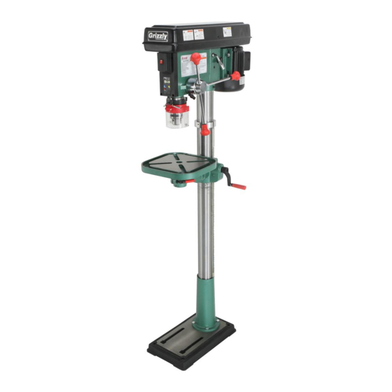
MODEL G0794
FLOOR DRILL PRESS
WITH LASER AND DRO
MANUAL INSERT
The Model G0794 is the same machine as the Model G7944, except the G0794 has a digital readout for
spindle downfeed, and it is equipped with a laser drilling guide in place of the work light. Aside from the dif-
ferences noted in this insert, all other content in the Model G7944 owner's manual applies to this machine.
: To reduce the risk of serious injury, you MUST read and understand this insert—and
the entire Model G7944 manual—BEFORE assembling, installing, or operating this machine!
If you have any further questions about this manual insert or the differences between the Model G0794
and the Model G7944, contact our Technical Support at (570) 546-9663 or email techsupport@grizzly.com.
COPYRIGHT © DECEMBER, 2014 BY GRIZZLY INDUSTRIAL, INC. REVISED MARCH, 2019 (KB)
WARNING: NO PORTION OF THIS MANUAL MAY BE REPRODUCED IN ANY SHAPE
OR FORM WITHOUT THE WRITTEN APPROVAL OF GRIZZLY INDUSTRIAL, INC.
(FOR MODELS MANUFACTURED SINCE 05/18) #WK16957 PRINTED IN CHINA
Advertisement
Table of Contents

Related Manuals for Grizzly G0794


Summary of Contents for Grizzly G0794
- Page 1 MANUAL INSERT The Model G0794 is the same machine as the Model G7944, except the G0794 has a digital readout for spindle downfeed, and it is equipped with a laser drilling guide in place of the work light. Aside from the dif- ferences noted in this insert, all other content in the Model G7944 owner's manual applies to this machine.
- Page 2 MACHINE DATA SHEET Customer Service #: (570) 546-9663 · To Order Call: (800) 523-4777 · Fax #: (800) 438-5901 MODEL G0794 FLOOR DRILL PRESS WITH LASER AND DRO Product Dimensions: Weight................................146 lbs. Width (side-to-side) x Depth (front-to-back) x Height................14 x 24 x 64 in.
- Page 3 The information contained herein is deemed accurate as of 3/26/2019 and represents our most recent product specifications. Model G0794 PAGE 2 OF 2 Due to our ongoing improvement efforts, this information may not accurately describe items previously purchased. Model G0794 (Mfd. Since 05/18)
- Page 4 Connect drill press to power. Turn laser Figure 3. Crosshairs aligned with indentation on ON using switch on front of drill press (see Figure 1). workpiece. Laser ON/ OFF Switch Figure 1. Location of laser ON/OFF switch. Model G0794 (Mfd. Since 05/18)
- Page 5 Remove (4) M4 x 12 tap screws shown in Figure 5, and remove DRO unit from hous- ing. The model G0794 is equipped with a digital read- out (DRO) for precision spindle adjustment. The DRO is independently powered by a SR44 but- ton cell battery, which may need to be changed from time to time.
- Page 6 Technical Support at (570) 546-9663. The photos and diagrams included in this section are best viewed in color. You can view these pages in color at www.grizzly.com. Model G0794 (Mfd. Since 05/18)
- Page 7 Laser Motor 110V Neutral Figure 7. Start capacitor. Ground Ground Ground Motor Junction 110 VAC From 5-15 Plug Plug To Motor Figure 8. Motor junction box and terminal block. READ ELECTRICAL SAFETY Model G0794 (Mfd. Since 09/14) ON PAGE 6!
- Page 8 Main Parts 58-3 58-4 58-6 58-1 58-2 58-7 58-8 58-9 58-10 58-11V2 35 36 124 125 Model G0794 (Mfd. Since 05/18)
- Page 9 LASER SWITCH KCD1-101 2/8A 250VAC P0794052 SHIFTER P0794098 GRIZZLY SAFETY PADDLE SWITCH P0794053 MOTOR MOUNT SLIDE BAR (SOLID) P0794099 INT RETAINING RING 35MM P0794054 MOTOR MOUNT SLIDE BAR (GROOVED) P0794100 POWER CORD 18G 3W 73" 5-15P Model G0794 (Mfd. Since 05/18)
- Page 10 PHLP HD SCR M4-.7 X 12 P0794121 CHUCK GUARD ASSEMBLY P0794137 HEX NUT M4-.7 P0794122 SWITCH PLATE P0794138 LASER LIGHT ASSEMBLY BY-11-1 P0794123 PHLP HD SCR M4-.7 X 10 P0794144 WASHER 6MM RUBBER P0794124 SWITCH PLATE -10- Model G0794 (Mfd. Since 05/18)
- Page 11 Safety labels help reduce the risk of serious injury caused by machine hazards. If any label comes off or becomes unreadable, the owner of this machine MUST replace it in the original location before resuming operations. For replacements, contact (800) 523-4777 or www.grizzly.com. -11-...
- Page 12 -12- Model G0794 (Mfd. Since 05/18)
- Page 13 G7943 G7944 184841 COPYRIGHT © 1992 BY GRIZZLY INDUSTRIAL, INC. REVISED MAY, 2018 (ABKB) WARNING: NO PORTION OF THIS MANUAL MAY BE REPRODUCED IN ANY SHAPE OR FORM WITHOUT THE WRITTEN APPROVAL OF GRIZZLY INDUSTRIAL, INC. #BL3698 PRINTED IN CHINA...
- Page 14 This manual provides critical safety instructions on the proper setup, operation, maintenance, and service of this machine/tool. Save this document, refer to it often, and use it to instruct other operators. Failure to read, understand and follow the instructions in this manual may result in fire or serious personal injury—including amputation, electrocution, or death.
-
Page 15: Table Of Contents
Table of Contents INTRODUCTION ..........2 SECTION 5: ACCESSORIES ......33 Contact Info............ 2 SECTION 6: MAINTENANCE ......35 Machine Description ........2 General ............35 Manual Accuracy ........... 2 Cleaning & Protecting ........35 Identification ........... 3 Lubrication ........... 35 Controls &... -
Page 16: Introduction
ID label. This will help us help you faster. tions, specifications, drawings, and photographs in this manual. Sometimes we make mistakes, but Grizzly Technical Support our policy of continuous improvement also means that sometimes the machine you receive is 1815 W. -
Page 17: Identification
Identification Become familiar with the names and locations of the controls and features shown below to better understand the instructions in this manual. Right-Side Controls Left-Side Controls A. ON/OFF Switch G. Spindle Return Spring B. Light Switch H. Depth Stop C. -
Page 18: Controls & Components
Controls & E. Belt Tension Locks: Two knobs on each side of headstock lock motor in place. Components Table Height Crank: Raises/lowers table. G. Table Rotation Lock Lever: Locks table rotation. To reduce your risk of serious injury, read this entire manual BEFORE... -
Page 19: G7943 Machine Data Sheet
G7943 Machine Data Sheet MACHINE DATA SHEET Customer Service #: (570) 546-9663 · To Order Call: (800) 523-4777 · Fax #: (800) 438-5901 MODEL G7943 14" HEAVY‐DUTY BENCHTOP DRILL PRESS Product Dimensions: Weight................................133 lbs. Width (side-to-side) x Depth (front-to-back) x Height..............14-1/2 x 24 x 38 in. Footprint (Length x Width).......................... - Page 20 Main Specifications: Operation Information Type................................. Bench Swing................................. 14 in. Spindle Taper............................MT#2 Spindle Travel............................3-1/4 in. Max. Distance From Spindle to Column...................... 7 in. Max. Distance From Spindle to Table......................16 in. Number of Spindle Speeds..........................12 Range of Spindle Speeds......................140 – 3050 RPM Max.
-
Page 21: G7944 Machine Data Sheet
G7944 Machine Data Sheet MACHINE DATA SHEET Customer Service #: (570) 546-9663 · To Order Call: (800) 523-4777 · Fax #: (800) 438-5901 MODEL G7944 14" HEAVY‐DUTY FLOOR DRILL PRESS Product Dimensions: Weight................................146 lbs. Width (side-to-side) x Depth (front-to-back) x Height..............14-1/2 x 24 x 64 in. Footprint (Length x Width).......................... - Page 22 Spindle Information Distance From Spindle to Base......................... 49 in. Quill Diameter............................2.040 in. Table Information Max. Table Tilt (Left/Right)........................90 deg. Table Swing............................360 deg. Table Swivel Around Center......................... 360 deg. Table Swivel Around Column....................... 360 deg. Max. Movement of Work Table......................25-3/4 in. Table Length............................
-
Page 23: Section 1: Safety
SECTION 1: SAFETY For Your Own Safety, Read Instruction Manual Before Operating This Machine The purpose of safety symbols is to attract your attention to possible hazardous conditions. This manual uses a series of symbols and signal words intended to convey the level of impor- tance of the safety messages. - Page 24 WEARING PROPER APPAREL. Do not wear FORCING MACHINERY. Do not force machine. clothing, apparel or jewelry that can become It will do the job safer and better at the rate for entangled in moving parts. Always tie back or which it was designed. cover long hair.
-
Page 25: Additional Safety For Drill Presses
Additional Safety for Drill Presses Serious injury or death can occur from getting clothing, jewelry, or long hair entangled in rotating spindle or bit/cutting tool. Contact with rotating bit/cutting tool can result in severe cuts or amputation of fingers. Flying metal chips can cause blindness or eye injuries. Broken bits/ cutting tools, unsecured workpieces, chuck keys, or other adjustment tools thrown from rotating spindle can strike nearby operator or bystanders with deadly force. -
Page 26: Section 2: Power Supply
SECTION 2: POWER SUPPLY Availability Before installing the machine, consider the avail- ability and proximity of the required power supply Serious injury could occur if you connect circuit. If an existing circuit does not meet the machine to power before completing setup requirements for this machine, a new circuit must process. - Page 27 Grounding & Plug Requirements Improper connection of the equipment-grounding wire can result in a risk of electric shock. The This machine MUST be grounded. In the event wire with green insulation (with or without yellow of certain malfunctions or breakdowns, grounding stripes) is the equipment-grounding wire.
-
Page 28: Section 3: Setup
(570) 546-9663. IMPORTANT: Save all packaging materials until you are completely satisfied with the machine and have resolved any issues between Grizzly or the SUFFOCATION HAZARD! shipping agent. You MUST have the original pack- Keep children and pets away aging to file a freight claim. -
Page 29: Inventory
Inventory Description The following is a list of items shipped with your A. Table ............1 machine. Before beginning setup, lay these items out and inventory them. B. Table Support Assembly ......1 C. Small Lock Lever ........1 If any non-proprietary parts are missing (e.g. a D. -
Page 30: Cleanup
Cleanup Cleanup Gasoline and petroleum products have low flash The unpainted surfaces of your machine are points and can explode coated with a heavy-duty rust preventative that or cause fire if used to prevents corrosion during shipment and storage. clean machinery. Avo i d This rust preventative works extremely well, but it u sing t h e s e p r o du c t s will take a little time to clean. -
Page 31: Site Considerations
Site Considerations Weight Load Physical Environment Refer to the Machine Data Sheet for the weight The physical environment where the machine is of your machine. Make sure that the surface upon operated is important for safe operation and lon- which the machine is placed will bear the weight gevity of machine components. -
Page 32: Mounting G7943 To Bench
Mounting G7943 to Anchoring to Floor Bench Number of Mounting Holes ......4 Diameter of Mounting Hardware ....⁄ " The Model G7943 should be secured to a bench. Anchoring machinery to the floor prevents tipping Items Needed or shifting and reduces vibration that may occur Assembled Drill Press ........1 during operation, resulting in a machine that runs Diameter of Mounting Hardware ..... -
Page 33: Mounting G7944 To Mobile Base
Mounting G7944 to Items Needed Plywood ⁄ " x 23 ⁄ " x 23 ⁄ " ....... 2 Mobile Base Wood Glue......... As Needed Wood Screws #6 x 1 ⁄ " ........24 Hex Bolts (2 ⁄ " Long, Sized for Base Plate) ..4 Hex Nuts (Sized for Hex Bolts) ...... -
Page 34: Assembly
Assembly With help of an assistant, place drill press on base plate. Position drill press close to front of mobile The machine must be fully assembled before it base, so mobile base will not become a trip- can be operated. Before beginning the assembly ping hazard. - Page 35 Place pinion in table support, as shown in Place rack inside of table support assembly, Figure 13, so pinion and gear teeth mesh mesh it with pinion, and slide table support/ together. rack assembly over column, as shown in Figure 15. Pinion Figure 13.
- Page 36 11. Thread small lock lever into front part of table 15. Remove headstock from box and place it on Styrofoam packing you laid out in Step 14. support assembly approximately three turns, for now. The assembly should match what is shown in Figure 17.
- Page 37 19. Suspend a plumb bob from center of 22. To install chuck guard, place chuck guard headstock spindle so it is over tape/ruler as over flange of depth gauge mount, as shown shown in Figure 19. in Figure 21, then tighten Phillips head screw and hex nut to secure it.
-
Page 38: Joining Drill Chuck & Arbor
Joining Drill Chuck 25. Insert table shaft into table support assembly. & Arbor 26. Tighten small locking lever to secure table in table support assembly. The table should now be installed, as shown in Figure 23. An arbor is included for the drill chuck that comes with this machine. -
Page 39: Test Run
Test Run To test run the machine: Clear all setup tools away from machine. Once assembly is complete, test run the machine Connect machine to power supply. to ensure it is properly connected to power and safety components are functioning correctly. Turn machine ON, verify motor operation, and then turn machine OFF. -
Page 40: Section 4: Operations
V-belt configuration chart located inside ects. Regardless of the content in this sec- belt cover. tion, Grizzly Industrial will not be held liable for accidents caused by lack of training. Connects machine to power, and turns machine ON. -
Page 41: Choosing Speeds
Choosing Speeds Using the Drill Bit Speed Chart Lubrication Suggestions The chart shown in Figure 27 is intended as Wood ............None a guide only. Always follow the manufacturer's Plastics ..........Soapy Water speed recommendations if provided with your Brass .......Water-Based Lubricant drill bits, cutters, or hole saws. -
Page 42: Changing Speeds
Changing Speeds Locate the desired speed on the speed chart under the belt cover and move the V-belts to the desired V-grooves on the motor, idler, and spindle pulleys. The Model G7943/G7944 are capable of 12 dif- ferent spindle speed RPMs. Spindle speed is For Example: As indicated in the speed controlled by the configuration of V-belts and chart for 540 RPM (Figure 30), a belt combi-... -
Page 43: Drilling
Drilling SOFT MATERIAL: Soft materials require a faster drilling speed. (NOTE: Plastics can melt at too high of a spindle speed!) The Model G7943/G7944 is designed for drilling LUBRICANT: Use some form of lubricant on holes in wood or metal. The basic operation of a all materials except wood. -
Page 44: Installing/Removing Drill Bits
Installing/Removing Depth Stop Drill Bits The Model G7943/G7944 has a depth stop that allows you to drill repeated non-through holes to Any drill bit you install in the chuck must be the same depth every time. tight enough that it will not come loose during operation. -
Page 45: Positioning Table
Positioning Table Table Height Loosen the column lock lever. Adjust the height. The table can raised/lowered, rotated, and tilted 90° left or right. Table adjustment controls are Tighten the column lock lever. shown in Figure 32. Table Rotation Column Loosen the table rotation lock lever. Lock Table Lever... -
Page 46: Removing Arbor
Removing Arbor Rotate the spindle until the inner drift-key slot is aligned with the outer slot, as shown in Figure 34. You will see through the spindle when the slot is properly aligned. The arbor can be removed to install other Morse Taper tooling in the spindle. -
Page 47: Section 5: Accessories
To reduce this risk, only install accessories recommended for this machine by Grizzly. NOTICE Refer to our website or latest catalog for additional recommended accessories. - Page 48 ⁄ ", and ⁄ ". Patented in the US! Figure 42. Model G8581 ⁄ " Keyless Drill Chuck JT#33. Figure 40. H8203 Professional Drill Bit Sharpening Machine. www.grizzly.com 1-800-523-4777 order online at or call -34- Model G7943/G7944 (Mfd. Since 09/17)
-
Page 49: Section 6: Maintenance
SECTION 6: MAINTENANCE Cleaning & Protecting To reduce risk of shock or accidental startup, always disconnect machine from power before adjustments, Cleaning the Model G7943/G7944 is relatively maintenance, or service. easy. Vacuum excess wood chips and sawdust, and wipe off the remaining dust with a dry cloth. If any resin has built up, use a resin-dissolving General cleaner to remove it. -
Page 50: Section 7: Service
SECTION 7: SERVICE Review the troubleshooting and procedures in this section to fix or adjust your machine if a problem devel- ops. If you need replacement parts or you are unsure of your repair skills, then feel free to call our Technical Support at (570) 546-9663. - Page 51 Drill Press Operations Symptom Possible Cause Possible Solution Tool loose/lack of 1. Tool incorrectly installed in spindle taper. 1. Remove and re-install (Page 32). power in spindle. 2. Debris on tool or spindle taper mating 2. Clean tool and spindle taper. surfaces.
-
Page 52: Calibrating Depth Stop
Calibrating Depth Tensioning Spindle Stop Return Spring The drill press comes fitted with a depth stop The tension of the spindle return spring makes the to use when drilling multiple holes at the same spindle automatically return to the top (starting) depth. - Page 53 While holding the spring lock cover against Put on heavy leather gloves to protect your the side of the headstock so the cover stays hands from possible lacerations if the spring splined with the locking lug, as shown in uncoils during the next step. Figure 45, loosen the jam nut and loosen the cover nut approximately ⁄...
-
Page 54: Section 8: Wiring
Technical Support at (570) 546-9663. The photos and diagrams included in this section are best viewed in color. You can view these pages in color at www.grizzly.com. -40- Model G7943/G7944 (Mfd. Since 09/17) -
Page 55: Electrical Components
Electrical Components Light Switch Power Switch Figure 46. Power and light switch assembly. Figure 48. Motor wiring inside junction box. Light Socket Capacitor Figure 47. Light socket with dust plug removed. Figure 49. Start capacitor. READ ELECTRICAL SAFETY -41- Model G7943/G7944 (Mfd. Since 09/17) ON PAGE 40! -
Page 56: G7943/G7944 Wiring Diagram
G7943/G7944 Wiring Diagram Light Socket Start Capacitor 200uF 125V Neutral 120 VAC Ground 5-15 Plug Ground (Preinstalled) Light WARNING! Switch SHOCK HAZARD! Disconnect power before working on Ground wiring. Power Switch READ ELECTRICAL SAFETY -42- Model G7943/G7944 (Mfd. Since 09/17) ON PAGE 40! -
Page 57: Section 9: Parts
58-5 58-7V2 56A 57 48 49 G7944 ONLY 23A-4 23A-2 23A-3 23A-1V2 100B 100C 121-1 121-1 121-2 121-2 121-4 121-5 121-3 BUY PARTS ONLINE AT GRIZZLY.COM! -43- Model G7943/G7944 (Mfd. Since 09/17) Scan QR code to visit our Parts Store. - Page 58 PHLP HD SCR M5-.8 X 12 P7943090 ARBOR P7943047 TAP SCREW M4.2 X 9 P7943091 CHUCK P7943048 PHLP HD SCR M5-.8 X 10 P7943092 CHUCK KEY BUY PARTS ONLINE AT GRIZZLY.COM! -44- Model G7943/G7944 (Mfd. Since 09/17) Scan QR code to visit our Parts Store.
- Page 59 WING NUT M5-.8 We do our best to stock replacement parts when possible, but we cannot guarantee that all parts shown are available for purchase. Call (800) 523-4777 or visit www.grizzly.com/parts to check for availability. BUY PARTS ONLINE AT GRIZZLY.COM! -45- Model G7943/G7944 (Mfd.
-
Page 60: G7943/G7944 Labels & Cosmetics
Safety labels help reduce the risk of serious injury caused by machine hazards. If any label comes off or becomes unreadable, the owner of this machine MUST replace it in the original location before resuming operations. For replacements, contact (800) 523-4777 or www.grizzly.com. BUY PARTS ONLINE AT GRIZZLY.COM! -46- Model G7943/G7944 (Mfd. - Page 61 Would you recommend Grizzly Industrial to a friend? _____ Yes _____No Would you allow us to use your name as a reference for Grizzly customers in your area? Note: We never use names more than 3 times. _____ Yes _____No 10.
- Page 62 FOLD ALONG DOTTED LINE Place Stamp Here GRIZZLY INDUSTRIAL, INC. P.O. BOX 2069 BELLINGHAM, WA 98227-2069 FOLD ALONG DOTTED LINE Send a Grizzly Catalog to a friend: Name_______________________________ Street_______________________________ City______________State______Zip______ TAPE ALONG EDGES--PLEASE DO NOT STAPLE...
-
Page 63: Warranty And Returns
WARRANTY AND RETURNS Grizzly Industrial, Inc. warrants every product it sells for a period of 1 year to the original purchaser from the date of purchase. This warranty does not apply to defects due directly or indirectly to misuse, abuse, negligence, accidents, repairs or alterations or lack of maintenance.