
Related Manuals for Dell DAE2-ATA


Summary of Contents for Dell DAE2-ATA
- Page 1 EMC CLARiiON 2-Gigabit Disk-Array Enclosure (DAE2) FC and ATA Models HARDWARE REFERENCE P/N 014003048 REV A05 EMC Corporation Corporate Headquarters : Hopkinton, MA 01748 9103 1000 www.EMC.com...
- Page 2 Copyright © 2002-2004 EMC Corporation. All rights reserved. Published January, 2004 EMC believes the information in this publication is accurate as of its publication date. The information is subject to change without notice. THE INFORMATION IN THIS PUBLICATION IS PROVIDED "AS IS." EMC CORPORATION MAKES NO REPRESENTATIONS OR WARRANTIES OF ANY KIND WITH RESPECT TO THE INFORMATION IN THIS PUBLICATION, AND SPECIFICALLY DISCLAIMS IMPLIED WARRANTIES OF MERCHANTABILITY OR FITNESS FOR A PARTICULAR PURPOSE.
- Page 3 Regulatory Notices Product Type(s) KAE, KLE This device complies with Part 15 of the FCC rules. Operation is subject to the following two conditions: (1) this device may not cause harmful interference, and (2) this device must accept any interference received, including interference that may cause undesired operation.
- Page 4 2-Gigabit Disk-Array Enclosure (DAE2) Hardware Reference...
-
Page 5: Table Of Contents
Contents Preface ..........................ix Warnings and Cautions ..................xiii Chapter 1 About DAE2 Disk Enclosures Introduction ..................1-2 Midplane ..................1-6 Front Bezel ................. 1-6 Link Control Cards (LCCs)............. 1-7 Disk Modules..................1-8 Disk Drives ................1-8 Drive Carrier ................1-8 Power Supply/System Cooling Modules ........ - Page 6 Contents Chapter 3 Servicing a DAE2 Monitoring Disk Enclosure Status ..........3-2 Handling FRUs ................3-6 Power Issues and FRUs ............3-6 Avoiding Electrostatic Discharge (ESD) Damage ....3-6 Emergency Procedures (Without an ESD Kit)...... 3-7 Precautions When Removing, Installing, or Storing FRUs 3-8 Replacing or Adding a Disk Module ..........
- Page 7 Figures Figure DAE2 ......................1-2 DAE2 Front LED Display ................1-4 Disk Enclosure Rear View ................1-5 Disk Enclosure Rear Displays ..............1-5 Disk Enclosure Front Bezel ................. 1-6 LCC Connectors and LEDs ................. 1-7 Disk Modules ....................1-8 Power/Cooling Module ................1-9 Setting the Enclosure Address (EA) ............
- Page 8 Figures 3-12 Installing an LCC ..................3-17 3-13 Reconnecting a Copper Cable to an LCC ..........3-18 3-14 Connecting Disk Enclosures Together with Copper Cable ....3-19 3-15 Unplugging the ac Power Cord ..............3-20 3-16 Removing a Power/Cooling Module ............3-21 3-17 Installing a Power/Cooling Module ............
-
Page 9: Preface
This manual is your primary source of information about EMC 2-gigabit disk-array enclosure (DAE2) hardware. It covers DAE2 models that use Fibre Channel disks, and DAE2-ATA models that include Advanced Technology Attachment drives. The DAE2 is often called a disk enclosure. - Page 10 Preface Related Cabinet Setup Guide for the 40U Cabinet (P/N 014003099) Documentation Site Preparation and Unpacking Guide for the 40U Cabinet (P/N 014003100) EMC Rails and Enclosures Installation Guide for 19-Inch NEMA Cabinets (P/N 014003082) EMC 2-Gigabit Disk Enclosure (DAE2) Setup Guide (P/N 014003104) EMC Navisphere Manager Revision 6.X Administrator’s Guide (P/N 069001161) EMC CLARiiON CX300, CX500, and CX700 Storage Systems...
- Page 11 Preface WARNING A warning contains information essential to avoid a hazard that can cause severe personal injury, death, or substantial property damage if you ignore the warning. DANGER A danger notice contains information essential to avoid a hazard that will cause severe personal injury, death, or substantial property damage if you ignore the message.
- Page 12 Preface To access EMC Powerlink, use the following link: http://powerlink.emc.com After you log in, select Support > Document Library and find the following: The FLARE™ software release notes The latest version of this reference. EMC Installation Roadmap for CX-Series and FC-Series Storage Systems, which provides a checklist of the tasks that you must complete to install your storage system in a storage area network (SAN) or direct attach configuration.
-
Page 13: Warnings And Cautions
Warnings and Cautions The following warnings and cautions pertain throughout this guide. WARNING Trained service personnel only. Ground circuit continuity is vital for safe operation of the machine. Never operate the machine with grounding conductors disconnected. Remember to reconnect any grounding conductors removed for or during any installation procedure. - Page 14 Warnings and Cautions Static Precautions EMC incorporates state-of-the-art technology in its designs, including the use of LSI and VLSI components. These chips are very susceptible to damage caused by static discharge and need to be handled accordingly. CAUTION Before handling printed-circuit boards or other parts containing LSI and/or VLSI components, observe the following precautions: Store all printed-circuit boards in antistatic bags.
-
Page 15: About Dae2 Disk Enclosures
Invisible Body Tag About DAE2 Disk Enclosures Topics in this chapter include Introduction ..................1-2 Link Control Cards (LCCs)...............1-7 Disk Modules..................1-8 Power Supply/System Cooling Modules ........1-9 About DAE2 Disk Enclosures... -
Page 16: Introduction
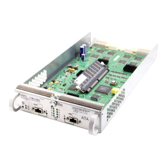
EMC produces two types of DAE2. The standard version includes high-performance Fibre Channel disk drives and FC-AL link control cards to manage them. The DAE2-ATA (Advanced Technology Attachment) version uses economical, high-capacity ATA disk drives and FC-to-ATA link control cards to manage the disks and provide an interface between the FC-AL and the drives. - Page 17 About DAE2 Disk Enclosures Any DAE2 can support up to fifteen 3.5-inch disk modules. Simple serial cabling provides easy scalability. You can interconnect DAE2s to Fibre Channel loops (sometimes called busses) to form a large disk storage system; the number and size of loops depends on the capabilities of your storage processor.
-
Page 18: Dae2 Front Led Display
About DAE2 Disk Enclosures provides slots for two identical components, the components are called component-name A or component-name B, as shown in the illustrations. For increased clarity, the following figures depict the disk enclosure outside of the rack cabinet. Your disk enclosure may be installed in a rackmount cabinet as shown in Figure 1-1. -
Page 19: Disk Enclosure Rear View
About DAE2 Disk Enclosures Enclosure Address Switch Power/Cooling Module B Link Control Card B (LCC B) Power/Cooling Module A Link Control Card A (LCC A) EMC2770 Disk Enclosure Rear View Figure 1-3 As shown in Figure 1-3 and Figure 1-4, an enclosure address (EA) switch/indicator is located between the power supplies at the rear of the disk enclosure. -
Page 20: Midplane
About DAE2 Disk Enclosures The enclosure address is set on the switch at installation. Disk module IDs are numbered left to right (looking at the front of the unit) and are contiguous throughout an array: enclosure 0 contains modules 0-14; enclosure 1 contains modules 15-29;... -
Page 21: Link Control Cards (Lccs)
About DAE2 Disk Enclosures Link Control Cards (LCCs) An LCC supports and controls one Fibre Channel loop and monitors the DAE2. Fault Loop (Amber) Latch ID LEDs Power (Green) Expansion Primary Expansion Primary Link Active Link Active Connector Connector (Green) (Green) EMC2165 LCC Connectors and LEDs... -
Page 22: Disk Modules
About DAE2 Disk Enclosures A latch on the LCC locks it into place to ensure proper connection to the midplane. You can add or replace an LCC while the disk enclosure is powered up. Disk Modules Each disk module consists of one disk drive in a carrier. You can add or remove a disk module while the DAE2 is powered up, but should exercise special care when removing modules while they are in use. -
Page 23: Power Supply/System Cooling Modules
About DAE2 Disk Enclosures The latch holds the disk module in place to ensure proper connection with the midplane. Disk drive Activity/Fault LEDs are integrated into the carrier. Power Supply/System Cooling Modules The power supply/system cooling (power/cooling) modules are located above the LCCs. The units integrate independent power supply and dual-blower cooling assemblies into a single module. - Page 24 About DAE2 Disk Enclosures 1-10 2-Gigabit Disk-Array Enclosure (DAE2) Hardware Reference...
-
Page 25: Installing A Dae2
Invisible Body Tag Installing a DAE2 This chapter describes the DAE2 installation requirements and procedures. Major topics are Requirements..................2-2 Installing a Disk Enclosure in a Cabinet .........2-3 Setting Up an Installed Disk Enclosure ..........2-4 Powerup and Initialization .............2-12 Binding Disk Modules into RAID Groups ........2-13 Installing a DAE2... -
Page 26: Requirements
Installing a DAE2 Requirements This section explains site and cabling requirements. Site Requirements For proper operation, the installation site must conform to certain environmental specifications. These are detailed below and in Appendix A. Power To determine a DAE2’s worst case power requirements, use the power rating on the enclosure label. -
Page 27: Installing A Disk Enclosure In A Cabinet
Installing a DAE2 EMC supports and can provide 1-, 5-, and 10-meter cables. The 5- and 10-meter cables are equalized. Interconnections between disk enclosures should maintain LCC consistency; that is, one Fibre Channel (FC) loop should interconnect all and only the LCC As, and the other Fibre Channel loop should interconnect all and only LCC Bs. -
Page 28: Setting Up An Installed Disk Enclosure
Installing a DAE2 Das Gehäuse ist schwer und sollte nur von zwei Personen in einem Rack installiert werden. Zur Vermeidung von körperlichen Verletzungen und/oder der Beschädigung des Gerätes, bitte das Gehäuse nicht ohne die Hilfe einer zweiten Person anheben und einbauen. -
Page 29: Setting The Enclosure Address (Ea)
Installing a DAE2 CAUTION Each drive reads its FC-AL physical address only at powerup or when the drive is reset. To avoid losing data, you must set the enclosure address when power is off; you cannot change the EA while power is on. 1. -
Page 30: Plugging In The Ac Line Cord
Installing a DAE2 Connector Retention Bail EMC2778 Plugging in the ac Line Cord Figure 2-2 Highly available, write-caching configurations require that you connect the first disk enclosure (EA 0, loop 0) to a Standby Power Supply (SPS) for enclosure power. If you do connect a DAE2 to an SPS (if, for example, the DAE2 is the first disk enclosure in a CX700-Series or CX600-Series configuration), be sure that you maintain power/loop integrity;... -
Page 31: Connecting Dae2 Power Cords
Installing a DAE2 Circuit Breaker DAE2 DAE2 Power DAE2 Connector DAE2 Power DAE2 Supply B Power Supply A SPS B SPS A Power Switch Power Switch SPS B SPS A EMC2780 Connecting DAE2 Power Cords Figure 2-3 3. Repeat steps 1 and 2 for each disk enclosure in the cabinet, as necessary. -
Page 32: Connecting A Disk Enclosure To Another Fc Device
Installing a DAE2 4. Attach the copper cable from the external device (storage processor or another DAE2) to the PRI connector as shown in Figure 2-4. If you are continuing the loop to another DAE2, attach a cable from the EXP connector to the PRI connector in the next DAE2. -
Page 33: Cabling Disk Enclosures Together - Two Fibre Channel Loops
Installing a DAE2 LCC B LCC A EA3/Loop 1 EA3/Loop 0 Loop 1 Loop 1 EA2/Loop 1 Loop 0 Loop 0 Loop 1 Loop 1 EA2/Loop 0 EA1/Loop 1 Loop 0 Loop 0 EA1/Loop 0 Loop 1 Loop 1 EA0/Loop 1 Loop 0 Loop 0 Loop 1... -
Page 34: Cabling Dae2S Together - Four Fibre Channel Loops
Installing a DAE2 Figure 2-6 shows a more complicated configuration with eight DAE2s and four redundant Fibre Channel loops. EA1/Loop 3 LCC B LCC A Loop 3 Loop 3 EA1/Loop 2 Loop 2 Loop 2 EA1/Loop 1 Loop 1 Loop 1 EA1/Loop 0 Loop 0 Loop 0... -
Page 35: Cabling Disk Enclosures Together - Segregated Loop Configuration
Installing a DAE2 LCC B LCC A DAE2 EA7/Loop 0 DAE2 EA6/Loop 0 Loop 0 Loop 0 LCC B LCC A DAE2 EA7/Loop 1 DAE2 EA5/Loop 0 Loop 0 Loop 0 Loop 1 Loop 1 DAE2 EA6/Loop 1 DAE2 EA4/Loop 0 Loop 0 Loop 0 Loop 1... -
Page 36: Powerup And Initialization
Installing a DAE2 Do not power up a disk enclosure without at least one LCC installed. You can configure a driveless disk enclosure within a Fibre Channel loop. High availability with write-caching requires disks in slots 0-4 in the first DPE2 or DAE2 connected to a storage processor (Enclosure Address 0, loop 0). -
Page 37: Binding Disk Modules Into Raid Groups
Installing a DAE2 Binding Disk Modules into RAID Groups ® After cabling the disk enclosure, use EMC Navisphere Manager software to bind the disks into RAID groups. Refer to the EMC Navisphere Manager Revision 6.X Administrator’s Guide and your storage processor configuration and planning guide for detailed information. - Page 38 Installing a DAE2 2-14 2-Gigabit Disk-Array Enclosure (DAE2) Hardware Reference...
-
Page 39: Figure 1-1 Dae2
Invisible Body Tag nvisible Servicing a DAE2 This chapter describes how to monitor disk enclosure status, handle FRUs, and replace or add a Field Replaceable Unit (FRU). Topics are Monitoring Disk Enclosure Status...........3-2 Handling FRUs...................3-6 Replacing or Adding a Disk Module ..........3-9 Replacing an LCC Module .............3-15 Replacing a Power Supply/System Cooling Module....3-20 DAE2... -
Page 40: Monitoring Disk Enclosure Status
Servicing a DAE2 Monitoring Disk Enclosure Status Status lights on the DAE2 and its FRUs indicate error conditions. These lights are visible outside the disk enclosure. Some lights are visible from the front, and the others from the back. Figures 3-1 through 3-4 and Tables 3-1 through 3-3 describe the status lights. - Page 41 Servicing a DAE2 Status Lights Visible from the Front of the Disk Enclosure Table 3-1 Light Quantity Color Meaning Disk Enclosure Power Green Power to enclosure is on. Disk Enclosure Fault Amber On when any fault condition exists; if the fault is not obvious from a disk module light, look at the back of the disk enclosure.
-
Page 42: Power/Cooling Module Status Indicators
Servicing a DAE2 Enclosure Address Loop ID EMC2771 Enclosure Address and Loop ID Indicators Figure 3-2 Table 3-2 describes the ID indicators. Enclosure and Loop ID Indicators Table 3-2 Light Quantity Color Meaning Enclosure Address 1 Green Displayed number indicates Enclosure Address Loop ID Green Displayed number indicates Loop ID... -
Page 43: Lcc Status Leds
Servicing a DAE2 Figure 3-4 shows the status LEDs for the link control cards. Fault Loop (Amber) ID LEDs Power (Green) Expansion Primary Link Active Link Active (Green) (Green) EMC2221 LCC Status LEDs Figure 3-4 Table 3-3 describes the status LEDs visible from the rear of the disk enclosure. -
Page 44: Handling Frus
Servicing a DAE2 When a redundant FRU fails, high availability will be compromised until you replace the faulty FRU. Handling FRUs This section describes the precautions that you must take and the general procedures you must follow when removing, installing, and storing FRUs. -
Page 45: Emergency Procedures (Without An Esd Kit)
Servicing a DAE2 Do not remove replacement or upgrade FRUs from their antistatic packaging until you are ready to install them. Gather together the ESD kit and all other materials you will need before you service a disk enclosure. Once servicing begins, you should avoid moving away from the work site;... -
Page 46: Precautions When Removing, Installing, Or Storing Frus
Servicing a DAE2 Precautions When Use the precautions listed below when you remove, handle, or store Removing, FRUs: Installing, or Storing Do not remove a faulty FRU until you have a replacement FRUs available. Handle a FRU only when using an ESD wristband. Attach the clip of the ESD wristband to the ESD bracket or bare metal on the enclosure, and put the wristband around your wrist with the metal button against your skin. -
Page 47: Replacing Or Adding A Disk Module
Servicing a DAE2 Replacing or Adding a Disk Module CAUTION Disk modules are extremely sensitive electronic components. Always handle a disk module gently, and observe the following guidelines: Always replace a disk drive with another of the same model; do not mix Fibre Channel and ATA components in the same enclosure. -
Page 48: Unlocking And Removing The Front Bezel
Servicing a DAE2 Unlocking and Removing the Front Bezel Follow these steps to remove the front bezel and gain access to the disk modules. Refer to Figure 3-5. 1. Insert the key that shipped with your enclosure into the bezel lock, and turn it to release the lock. -
Page 49: Removing A Disk Filler Module
Servicing a DAE2 Removing a Disk Filler Module Locate the slot where you want to install the disk module, and remove the filler module, as shown in Figure 3-6. EMC2210 Figure 3-6 Removing a Disk Filler Module (FC Disk Carrier Shown) Skip to the disk installation procedure (Page 3-12) to install the add-on disk in the slot you just emptied. -
Page 50: Installing A Disk Or Filler Module
Servicing a DAE2 2. If the active light is on steadily, pull the latch, and slowly pull the module about 1 in (3 cm) from its slot. Wait 30 seconds for the disk to stop spinning. Then remove the module and place it on a padded, static-free surface. -
Page 51: Installing A Disk Or Filler Module (Fc Disk Carrier Shown)
Servicing a DAE2 EMC2211 Figure 3-8 Installing a Disk or Filler Module (FC Disk Carrier Shown) The disk module’s Active light flashes to reflect the disk’s spin-up sequence. 4. Remove and store the ESD wristband and continue to the next section to install the front bezel. -
Page 52: Installing And Locking The Front Bezel
Servicing a DAE2 Installing and Locking the Front Bezel Refer to Figure 3-9 as you do the following: 1. Align the bezel with the disk enclosure. 2. Gently push the bezel into place on the cabinet until it latches. 3. Secure the bezel by turning the key in the lock. EMC2222 Installing and Locking the Front Bezel Figure 3-9... -
Page 53: Replacing An Lcc Module
Servicing a DAE2 Replacing an LCC Module CAUTION Handle an LCC gently and use an ESD wristband. Do not remove a faulty LCC until you have a replacement module available. A DAE2 must have at least one LCC installed while it is powered up. Do not remove both LCCs while the disk enclosure is powered up. -
Page 54: Installing An Lcc
Servicing a DAE2 2. Turn the latch counterclockwise to release the module, and then remove the LCC from its slot, as shown in Figure 3-11. Latch EMC2774 Figure 3-11 Removing an LCC Continue to the next section to install the replacement LCC. Installing an LCC 1. -
Page 55: Installing An Lcc
Servicing a DAE2 Latch EMC2776 Figure 3-12 Installing an LCC The LCC Power light turns on. 2. Turn the latch clockwise to secure the module. The DAE2 LCC latch holds the module in an established position. It does not pull or otherwise help to seat the LCC. 3. -
Page 56: Reconnecting A Copper Cable To An Lcc
Servicing a DAE2 Connector To other FC device EMC2772 Reconnecting a Copper Cable to an LCC Figure 3-13 4. Remove and store the ESD wristband. The configuration example in Figure 3-14 shows a CLARiiON® CX300 disk processor enclosure (DPE2) below three DAE2 disk-array enclosures. Note that the external device connects to the Primary disk enclosure connectors, and subsequent enclosures connect in an Expansion-to-Primary chain. -
Page 57: Connecting Disk Enclosures Together With Copper Cable
Servicing a DAE2 LCC B LCC A EA3/Loop 0 Loop 0 Loop 0 EA2/Loop 0 Loop 0 Loop 0 EA1/Loop 0 EA0/Loop 0 Loop 0 Loop 0 BE 0 BE 0 EMC2743 Connecting Disk Enclosures Together with Copper Cable Figure 3-14 3-19 Replacing an LCC Module... -
Page 58: Replacing A Power Supply/System Cooling Module
Servicing a DAE2 Replacing a Power Supply/System Cooling Module CAUTION Handle a power supply/system cooling (power/cooling) module gently and use an ESD wristband. Do not remove a power/cooling module until you have a replacement module available. Access to the disks in your enclosure will time out and the disks will spin down two minutes after a power/cooling module is removed from the enclosure. -
Page 59: Removing A Power/Cooling Module
Servicing a DAE2 2. Turn the latch counterclockwise to release the module, and then remove the power/cooling module as shown in Figure 3-16. To protect a running system from overheating, the enclosure will time out unless you replace the power/cooling module within two minutes. Latch EMC2773 Removing a Power/Cooling Module... -
Page 60: Plugging In The Power Cord
Servicing a DAE2 4. Turn the latch clockwise to secure the module. The latch holds the power/cooling module in an established position. It does not pull or otherwise help to seat the module. 5. Make sure any power switch on the replacement module is off before you plug the ac power cord into the new supply as shown in Figure 3-18. -
Page 61: Appendix A Technical Specifications
Invisible Body Tag Technical Specifications Body Tag This appendix describes the disk-array enclosure technical specifications, operating limits, and shipping and storage requirements. Major topics are Enclosure Specifications..............A-2 Operating Limits ................A-5 Technical Specifications... -
Page 62: Enclosure Specifications
Description Requirement DAE2 (Fibre Channel) DAE2-ATA ac line voltage 100 to 240 V ac + 10%, single phase, 47 to 63 Hz ac line current 4.0 A at 100 V ac, 1.6 A at 200 V ac 3.0 A at 100 Vac, 1.4 A at 200 V ac... -
Page 63: Size And Weight
Technical Specifications Size and Weight Requirement Measurement Height 133.35 mm (5.25 in) 3 NEMA units including mounting hardware Width 450 mm (17.72 in) Depth 603.25 mm (23.75 in) Weight 43.2 kg (95.3 lbs) maximum configuration 1.1 kg (2.4 lbs) per FC disk module; 1.125 kg (2.5 lbs) per ATA module 1.4 kg (3 lbs) per link control card 4.1 kg (9 lbs) per power supply... -
Page 64: Standards Certification And Compliance
CE Mark European EMC Directive & Low Voltage Directive Requirements NEBS/Bellcore* NEBS: Level 3 compliant, Physical Protection, EMC and Safety Bellcore: GR-63-CORE, GR-1089-CORE, SR-3580 * Standard DAE2. DAE2-ATA not tested for NEBS/Bellcore compliance. EMI Standards Standard Description FCC Part 15... -
Page 65: Operating Limits
Technical Specifications Operating Limits The ambient temperature specification is measured at the front bezel inlet. The site must have air conditioning of the correct size and placement to maintain the specified ambient temperature range. The air conditioning must be able to handle the heat dissipation requirements of the disk enclosures. -
Page 66: Shipping And Storage Requirements
Technical Specifications Shipping and Storage Requirements Requirement Description Ambient temperature C to 65 C (-40 F to 149 Temperature gradient C/hr (45 F/hr) Relative humidity 10% to 90% noncondensing Elevation 7625 m (25,000 ft) 2-Gigabit Disk-Array Enclosure (DAE2) Hardware Reference... -
Page 67: Customer Support
nvisible Body Tag Customer Support This appendix reviews the EMC process for detecting and resolving software problems, and provides essential questions that you should answer before contacting the EMC Customer Support Center. This appendix covers the following topics: Overview of Detecting and Resolving Problems ......B-2 Troubleshooting the Problem ............ -
Page 68: Overview Of Detecting And Resolving Problems
Customer Support Overview of Detecting and Resolving Problems EMC software products are supported directly by the EMC Customer Support Center in the United States. EMC uses the following process to resolve customer problems with its software products (Figure B-1). Problem Detection Refer to this Customer Support... -
Page 69: Troubleshooting The Problem
Customer Support Troubleshooting the Problem Please perform the relevant diagnostic steps before you contact the EMC Customer Support Center: 1. Read the documentation carefully. 2. Reconstruct the events leading up to the problem and describe them in writing. 3. Run some test cases to reproduce the problem. If you encounter a problem that requires technical programming or analysis, call the nearest EMC office or contact the EMC Customer Support Center at one of the following numbers:... -
Page 70: Before Calling The Customer Support Center
Customer Support Before Calling the Customer Support Center Have the following information available before calling the Customer Support Center or your support representative (if one has been assigned to you): Your company name Your name Your phone number For an existing problem, the problem tracking system ID, if one was previously assigned to the problem by a support representative For an MVS problem, the JESLOG, SYSPRINT, all STDOUT DD... -
Page 71: Documenting The Problem
Customer Support Documenting the Problem If the EMC Customer Support Center requests information regarding the problem, please document it completely, making sure to include the following information: Your company name and address Your name Your telephone number The importance of the problem, so that it can be assigned a priority level To expedite the processing of your support request, you can photocopy this list and include it with the package. -
Page 72: Reporting A New Problem
Customer Support Reporting a New Problem For a new problem, please provide the following information: Release level of the software that you are running Software installation parameters Host type on which you are running Operating system you are running and its release number Functions of the software that you are running Whether you can reproduce the problem Previous occurrences of the problem... -
Page 73: Sending Problem Documentation
Customer Support Sending Problem Documentation Use one of the following methods to send documentation of the problem to the EMC Customer Support Center: E-mail U.S. mail to the following address: EMC Customer Support Center 45 South Street Hopkinton, MA 01748-9103 If the problem was assigned a number or a specific support representative, please include that information in the address as well. - Page 74 Customer Support 2-Gigabit Disk-Array Enclosure (DAE2) Hardware Reference...
- Page 75 Index check light DAE2 components 3-2 ac power cord LCC 3-5 attaching to power supply 3-22 power supply 3-5 removing from power supply 3-20 comments xii ac power, current draw A-2 components 1-3 Active light Cooling Check light 3-5 LCC 3-5 current draw, DAE2 A-2 power supply 3-5 customer support xii, B-3...
- Page 76 Index disk module FRUs (field-replaceable units) adding 3-9 defined 1-3 binding into RAID groups 2-13 disk module description 1-8 adding 3-9 disk drive 1-8 description 1-8 drive carrier 1-8 removing 3-11 drive specifications A-3 replacing 3-9 replacing 3-9 handling 3-6 disks, configuration rules 2-13 documentation, related x adding 3-15...
- Page 77 Index midplane 1-6 RAID groups 2-13 monitoring 3-2 rear, description 1-5 recovery, environmental A-5 removing, disk module 3-11 replacing NEBS compliance A-4 disk module 3-9 LCC 3-15 power supply 3-20 requirements, cabling 2-2 overtemperature recovery A-5 service xii power shipping requirements A-6 issues and FRUs 3-6 site requirements 2-2 overview 2-2...
-
Page 78: Index
Index 2-Gigabit Disk-Array Enclosure (DAE2) Hardware Reference...