Dell PowerEdge FX2 Owner's Manual
Hide thumbs
Also See for PowerEdge FX2:
- User manual (154 pages) ,
- Deployment manual (107 pages) ,
- Configuration manual (24 pages)

Related Manuals for Dell PowerEdge FX2


Summary of Contents for Dell PowerEdge FX2
- Page 1 Dell PowerEdge FX2 and FX2s Enclosure Owner's Manual Regulatory Model: E24S Regulatory Type: E24S001...
- Page 2 WARNING: A WARNING indicates a potential for property damage, personal injury, or death. Copyright © 2015 Dell Inc. All rights reserved. This product is protected by U.S. and international copyright and intellectual property laws. Dell and the Dell logo are trademarks of Dell Inc.
-
Page 3: Table Of Contents
Contents 1 About your Dell PowerEdge FX2/FX2s.............. 7 ........................ 7 Terms used in the document ..........................9 Sled slot numbering ............. 10 Front panel features and indicators—PowerEdge FX2/FX2s ........................11 Diagnostic indicators .........................12 Power button functions ..........................13 KVM features ............13... - Page 4 4 Installing and removing PowerEdge FX2/FX2s enclosure components......................36 ............36 Customer and field replaceable units—PowerEdge FX2/FX2s ..........................36 Safety instructions ....................37 Before working inside your system ......................37 After working inside your system ...........................37 Recommended tools ............................37 System cover ......................37 Removing the system cover ......................
- Page 5 ..................... 88 Troubleshooting cooling problems ...................... 88 Troubleshooting cooling fans ....................89 Troubleshooting expansion cards ......................89 Troubleshooting I/O modules 6 Technical specifications—PowerEdge FX2/FX2s..........91 ........................91 Dimensions and weight ..........................91 Sled specifications ........................... 92 Power specifications ..............93 Chassis Management Controller (CMC) specifications ....................
-
Page 6: Getting Help
...................... 95 Expanded operating temperature 7 Getting help......................97 ........................... 97 Contacting Dell ...................... 97 Locating your system Service Tag ..................97 Accessing system information by using QRL... -
Page 7: About Your Dell Poweredge Fx2/Fx2S
About your Dell PowerEdge FX2/FX2s The Dell PowerEdge FX2/FX2s is a 2U enclosure that can support up to four half-width compute sleds, up to eight quarter-width compute sleds, up to two full-width compute sleds, or a mix of compute sled types. - Page 8 Term Description NOTE: For information on mapping of storage sleds to compute sleds in PowerEdge FX2s, see the Dell PowerEdge FD332 Owner’s Manual at Dell.com/poweredgemanuals. Four-bay chassis Refers to the PowerEdge FX2/FX2s enclosure configuration that supports up to four half-width compute sleds.
-
Page 9: Sled Slot Numbering
Sled slot numbering Figure 1. Sled slot numbering—four-bay chassis Figure 2. Sled slot numbering—eight-bay chassis Figure 3. Sled slot numbering—two-bay chassis Figure 4. Sled slot numbering — six-bay chassis Figure 5. Sled slot numbering—three-bay chassis... -
Page 10: Front Panel Features And Indicators-Poweredge Fx2/Fx2S
Front panel features and indicators—PowerEdge FX2/ FX2s Figure 6. Front panel features and indicators—PowerEdge FX2/FX2s Table 2. Front panel features and indicators—PowerEdge FX2/FX2s Item Indicator, Button, or Icon Description Connector System identification The identification buttons on the front and button back panels can be used to locate a particular system within a rack. -
Page 11: Diagnostic Indicators
NOTE: PowerEdge FX2s supports a combination of compute and storage sleds. For information on mapping of storage sleds to compute sleds in PowerEdge FX2s, see the Dell PowerEdge FD332 Owner's Manual at Dell.com/poweredgemanuals. Video connector Enables you to connect a monitor to the system. -
Page 12: Power Button Functions
Getting error. Help. Power button functions The following section describes the different functions of the power button on your PowerEdge FX2/FX2s enclosure. Chassis power The chassis power button is used to control power to the chassis and the button and chassis sleds. -
Page 13: Kvm Features
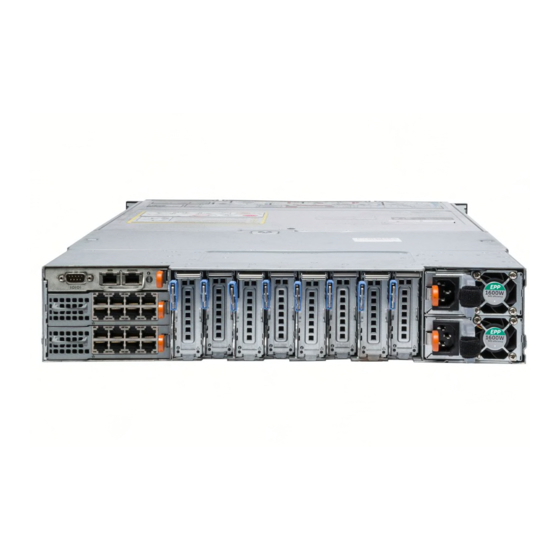
KVM provides access to the compute sleds. You can access one compute sled at a time by using the KVM select button. Back panel features and indicators—PowerEdge FX2s and Figure 7. Back panel features and indicators—PowerEdge FX2s Figure 8. Back panel features and indicators—PowerEdge FX2... -
Page 14: Power Supply Unit Indicators
Table 4. Back panel features and indicators—PowerEdge FX2 and PowerEdge FX2s enclosures Item Indicator, Button, or Description Connector Serial connector DB-9 serial connector for CMC configuration. Ethernet connector Gb1 Connects the network cable from the management system to the CMC. - Page 15 Figure 9. PSU indicators AC PSU status indicator/handle NOTE: The 2000 W PSU power cable connector is different from the connector shown in the image above. The PSU indicators provide the following information: Table 5. PSU indicators Convent Power indicator Condition pattern Green...
-
Page 16: I/O Module Indicators
Blinking Blue The CMC is identifying the I/O module. Blinking Amber The I/O module is in a fault condition. The I/O module is powered off, or booting is in progress. For more information, see the I/O module documentation at Dell.com/poweredgemanuals. -
Page 17: Cmc Module
CMC module Figure 12. CMC module DB-9 serial connector for local configuration Ethernet connector Gb1 link indicator activity indicator Ethernet connector STK/Gb2 (stack) system identification button NOTE: This port can also be used for CMC NIC failover. CMC indicators The CMC indicators on the back panel of the enclosure provide the following information: Indicator Description System... - Page 18 You must connect the STK port only to a Gb port that is further from the chain or network. NOTE: The CMC must be installed for the system to power on. See the PowerEdge FX2/FX2s CMC User’s Guide at Dell.com/poweredgemanuals for complete instructions on setting up and...
-
Page 19: Cooling Fan Indicator Codes
Figure 13. CMC daisy-chaining management network Cooling fan indicator codes Each cooling fan has an LED that indicates the power status of the cooling fan. Indicator Condition Pattern Not lit Cooling fan is functioning correctly. Flashing Amber Indicates a problem with the cooling fan. -
Page 20: Configuration Wizard
The CMC web interface displays system messages to notify you of possible problems related to the enclosure and to the sleds in the enclosure. For a detailed listing of these error messages, including possible causes and solutions, see the Dell Event and Error Messages Reference Guide at Dell.com/ openmanagemanuals → OpenManage software. -
Page 21: Documentation Matrix
Getting Started Guide specifications of your system Install the operating system Operating system documentation at Dell.com/ operatingsystemmanuals Get an overview of the Dell Systems Management Dell OpenManage Systems Management Overview offerings Guide at Dell.com/openmanagemanuals Install, configure, and use the Chassis Management Dell PowerEdge FX2/FX2s CMC User’s Guide at... -
Page 22: Accessing System Information By Using Qrl
Your system service tag to quickly access your specific hardware configuration and warranty information • A direct link to Dell to contact technical support and sales teams Steps Go to Dell.com/QRL and navigate to your specific product or Use your smartphone or tablet to scan the model-specific Quick Resource (QR) code located in the... -
Page 23: Initial System Configuration
Steps Unpack the enclosure and sled(s), and identify each item. For more information, see the Dell PowerEdge FX2 Getting Started With Your System and Rack Installation Guide at Dell.com/poweredgemanuals. WARNING: Whenever you need to lift the system, get others to assist you. To avoid injury, do not attempt to lift the system by yourself. -
Page 24: Logging In To The Cmc
You can log in to the CMC as a CMC local user, as a Microsoft Active Directory user, or as an LDAP user. You can also log in by using the Single Sign-On or Smart Card. For more information on managing the system and configuring the settings, see the Dell PowerEdge FX2/ FX2s CMC User’s Guide at Dell.com/esmmanuals. -
Page 25: Poweredge Fx2/Fx2S Mapping Configurations
LAN On Motherboard (LOM) network refers to the Ethernet connectivity provided to the compute sleds by the I/O modules installed at the back of the PowerEdge FX2/FX2s enclosure. LOM network provides four connections per half-width compute sled, two connections per quarter- width compute sled, and eight connections per full-width compute sled for a maximum of 16 lanes. -
Page 26: I/O Module Port Mapping-Four-Bay Chassis
Directed Attach Copper cables) between two 10 Gb pass-through modules is not supported. NOTE: This restriction is not applicable for Direct Attach Copper connections or to the 1 Gb pass-through module. NOTE: For more information on the I/O modules, see the I/O module documentation at Dell.com/ poweredgemanuals. I/O module port mapping—four-bay chassis The following I/O module port mapping options are available on the four-bay chassis configuration that supports up to four half-width compute sleds. -
Page 27: I/O Module Port Mapping-Eight-Bay Chassis
I/O module. The network traffic from the nodes in the compute sled to the I/O modules in the enclosure is routed through a network switch that is embedded on the compute sled system board. For more information, see the Dell PowerEdge FM120x4 Owner's Manual at Dell.com/poweredgemanuals. -
Page 28: I/O Module Port Mapping-Six-Bay Chassis
The following table lists the compute sleds and the ports to which they are mapped. Table 9. I/O module port mapping in eight-bay chassis Compute sled IO Module A1 (Top) IO Module A2 (Bottom) I/O module port mapping—six-bay chassis The six-bay chassis supports a combination of up to four quarter-width compute sleds and up to two half-width compute sleds. -
Page 29: I/O Module Port Mapping-Two-Bay Chassis
Table 10. I/O module port mapping in a six-bay chassis Compute IO Module A1 (Top) IO Module A2 (Bottom) sled 5, 6 (for half-width compute sled with quad- 5, 6 (for half-width compute sled with quad- port NDC) port NDC) 5 (for half-width compute sled with dual- 5 (for half-width compute sled with dual- port NDC) -
Page 30: I/O Module And Pcie Mezzanine Card Configuration Guidelines
In the three-bay chassis, a full-width compute sled is mapped to four ports on each I/O module. A half- width compute sled with quad port NDC is mapped to two ports on each I/O module. NOTE: A half-width compute sled with dual-port NDC is mapped to a single port on each I/O module. -
Page 31: Configuring Network Settings For The I/O Module
CMC Web interface • RACADM For more information on configuring the network settings, see the Dell PowerEdge FX2/FX2s CMC User’s Guide at Dell.com/esmmanuals. Expansion bus Expansion bus refers to the PCIe connections between the compute sleds and the PowerEdge FX2s enclosure. - Page 32 • Four-bay chassis—Each half-width compute sled is mapped to two PCIe slots. • Eight-bay chassis—Each quarter-width compute sled is mapped to one PCIe slot. • Six-bay chassis—Each quarter-width compute sled is mapped to one PCIe slot. Each half-width compute sled is mapped to two PCIe slots. •...
-
Page 33: Pcie Slot Mapping From Compute Sleds Mapped To Storage Sleds
You can enable or disable the PCIe reassignment option by using the CMC web interface, CMC WSMAN, or RACADM. For more information, see the PowerEdge FX2/FX2s CMC User’s Guide and the Dell Chassis Management Controller for PowerEdge FX2/FX2s RACADM Command Line Reference Guide at Dell.com/esmmanuals. - Page 34 Figure 27. PCIe slot mapping from compute sleds mapped to storage sleds—four-bay chassis Figure 28. PCIe slot mapping from compute sled mapped to storage sleds—four-bay chassis (with single compute sled) Figure 29. PCIe slot mapping from compute sled mapped to storage sleds—three-bay chassis...
-
Page 35: Managing Pcie Slots
You can view the status of PCIe slots in the system, both individually as well as all of them at a time. For more information on managing the PCIe slots by using the CMC web interface, see the Dell PowerEdge FX2/FX2s CMC User’s Guide at Dell.com/esmmanuals. -
Page 36: Installing And Removing Poweredge Fx2/Fx2S Enclosure Components
Installing and removing PowerEdge FX2/ FX2s enclosure components This section provides information on installing and removing the enclosure components. For information on removing and installing the sled components, see the relevant sled Owner’s Manual at Dell.com/ poweredgemanuals. Customer and field replaceable units—PowerEdge FX2/... -
Page 37: Before Working Inside Your System
Damage due to servicing that is not authorized by Dell is not covered by your warranty. Read and follow the safety instructions that came with the product. -
Page 38: Installing The System Cover
Damage due to servicing that is not authorized by Dell is not covered by your warranty. Read and follow the safety instructions that came with the product. -
Page 39: Sleds
Damage due to servicing that is not authorized by Dell is not covered by your warranty. Read and follow the safety instructions that came with the product. -
Page 40: Installing A Compute Sled
Damage due to servicing that is not authorized by Dell is not covered by your warranty. Read and follow the safety instructions that came with the product. -
Page 41: Removing A Storage Sled
Damage due to servicing that is not authorized by Dell is not covered by your warranty. Read and follow the safety instructions that came with the product. - Page 42 Figure 33. Removing a storage sled sled lock (2) dotted line on storage sled sled release latch (2) Figure 34. Removing and installing the I/O connector cover storage sled I/O connector cover Next steps Install the storage sled or sled blank. Related References Safety instructions...
-
Page 43: Installing A Storage Sled
(slot 3). In the four-bay chassis, you can also install a storage sled in the top right slot (slot 2) of the enclosure. For more information on sled slot numbering, see the Dell PowerEdge FX2 and FX2s Enclosure Owner's Manual at Dell.com/poweredgemanuals. -
Page 44: Inside The System
Damage due to servicing that is not authorized by Dell is not covered by your warranty. Read and follow the safety instructions that came with the product. - Page 45 Figure 36. Inside the system—PowerEdge FX2s midplane fan (8) power bus bar power interposer board Power Supply Unit (2) PCIe module (8) CMC module NOTE: PowerEdge FX2 does not support PCIe modules.
-
Page 46: Cmc Module
Damage due to servicing that is not authorized by Dell is not covered by your warranty. Read and follow the safety instructions that came with the product. -
Page 47: Installing The Cmc Module
Damage due to servicing that is not authorized by Dell is not covered by your warranty. Read and follow the safety instructions that came with the product. -
Page 48: I/O Module
Damage due to servicing that is not authorized by Dell is not covered by your warranty. Read and follow the safety instructions that came with the product. -
Page 49: Installing An I/O Module
Damage due to servicing that is not authorized by Dell is not covered by your warranty. Read and follow the safety instructions that came with the product. -
Page 50: Removing A Pcie Module
Damage due to servicing that is not authorized by Dell is not covered by your warranty. Read and follow the safety instructions that came with the product. -
Page 51: Installing A Pcie Module
Damage due to servicing that is not authorized by Dell is not covered by your warranty. Read and follow the safety instructions that came with the product. -
Page 52: Pcie Module Indicators
Table 14. Expansion card operational power status Chassis status Compute sled status Expansion card status Standby The following table provides information on the operational power status of an expansion card when it is replaced in the PCIe slot. Table 15. Expansion card operational power status Chassis status Compute sled status Expansion card status... -
Page 53: Removing An Expansion Card
Damage due to servicing that is not authorized by Dell is not covered by your warranty. Read and follow the safety instructions that came with the product. -
Page 54: Installing An Expansion Card
Damage due to servicing that is not authorized by Dell is not covered by your warranty. Read and follow the safety instructions that came with the product. -
Page 55: Removing A Power Supply Unit
Damage due to servicing that is not authorized by Dell is not covered by your warranty. Read and follow the safety instructions that came with the product. -
Page 56: Installing A Power Supply Unit
Damage due to servicing that is not authorized by Dell is not covered by your warranty. Read and follow the safety instructions that came with the product. - Page 57 Damage due to servicing that is not authorized by Dell is not covered by your warranty. Read and follow the safety instructions that came with the product.
-
Page 58: Installing A Cooling Fan
Damage due to servicing that is not authorized by Dell is not covered by your warranty. Read and follow the safety instructions that came with the product. - Page 59 Steps Loosen the six screws that secure the cooling-fan cage to the system. Lift the cooling-fan cage out of the system. Figure 44. Removing and installing the cooling-fan cage screw (6) cooling-fan cage Figure 45. Cooling-fan cage top view screw location (6) Next steps Install the cooling-fan cage.
-
Page 60: Installing The Cooling-Fan Cage
Damage due to servicing that is not authorized by Dell is not covered by your warranty. Read and follow the safety instructions that came with the product. - Page 61 NOTE: You must remove the PCIe switch board to replace a faulty switch board or service other components in the system. Ensure that you read the Safety instructions. Follow the procedure listed in Before working inside your system. Remove the following: •...
-
Page 62: Installing The Pcie Switch Board
Damage due to servicing that is not authorized by Dell is not covered by your warranty. Read and follow the safety instructions that came with the product. -
Page 63: Removing The Fan Interface Board
Damage due to servicing that is not authorized by Dell is not covered by your warranty. Read and follow the safety instructions that came with the product. -
Page 64: Installing The Fan Interface Board
Damage due to servicing that is not authorized by Dell is not covered by your warranty. Read and follow the safety instructions that came with the product. -
Page 65: Interposer Module
Interposer module The interposer module allows you to install quarter-width sleds in the PowerEdge FX2/FX2s enclosure that comes pre-installed with half-width or full-width sleds. Your system supports up to two interposer modules. Figure 48. Top view of the interposer module... -
Page 66: Removing The Bottom Interposer Module
Damage due to servicing that is not authorized by Dell is not covered by your warranty. Read and follow the safety instructions that came with the product. - Page 67 Figure 49. Removing and installing screws securing the bottom partition 1. bottom of the system 2. screw (5) b. Remove the two screws that secure the bottom interposer module. Figure 50. Removing and installing screws securing the bottom interposer module 1.
- Page 68 Figure 51. Removing and installing the bottom partition bottom partition screw (2) Remove the two screws that secure the bottom interposer module to the top of the system. Pull out the bottom interposer module from the system. Figure 52. Removing and installing the bottom interposer module bottom interposer module (2) screw (2) Next steps...
-
Page 69: Installing The Bottom Interposer Module
Damage due to servicing that is not authorized by Dell is not covered by your warranty. Read and follow the safety instructions that came with the product. -
Page 70: Removing The Top Interposer Module
Damage due to servicing that is not authorized by Dell is not covered by your warranty. Read and follow the safety instructions that came with the product. - Page 71 Figure 53. Removing and installing screws securing the top partition to the middle plate 1. middle plate 2. bottom of the system 3. screw (3) b. Remove the two screws that secure the top interposer module to the middle plate. Figure 54.
- Page 72 Figure 55. Removing and installing the top partition top partition screw (3) Remove the two screws that secure the top interposer module to the top of the system. Pull out the top interposer module from the system. Figure 56. Removing and installing the top interposer module top interposer module screw (2) Next steps...
-
Page 73: Installing The Top Interposer Module
Damage due to servicing that is not authorized by Dell is not covered by your warranty. Read and follow the safety instructions that came with the product. -
Page 74: Midplane Assembly
Damage due to servicing that is not authorized by Dell is not covered by your warranty. Read and follow the safety instructions that came with the product. - Page 75 Steps Lift the Mylar insulator from the midplane. Remove the two fan cables connected to the midplane. Remove the two screws that secure the fan cable clips to the system. Figure 57. Removing and installing midplane assembly components midplane fan-cable clip (2) screw (2) Mylar insulator Remove the five screws that secure the midplane assembly to the system.
- Page 76 Remove the screws that secure the KVM cover. Remove the screws that secure the cable tube on the right side of the chassis. 10. Place the cable tube on the chassis without removing the KVM panel cable and the KVM panel. 11.
- Page 77 Figure 60. Routing of the KVM and control panel cables on the midplane KVM cable connector KVM cable brackets on the midplane assembly to control panel cable route the KVM cable brackets on the midplane assembly to control panel cable connector route the control panel cable connector on the midplane 14.
-
Page 78: Installing The Midplane Assembly
Damage due to servicing that is not authorized by Dell is not covered by your warranty. Read and follow the safety instructions that came with the product. -
Page 79: Power Interposer Board
Damage due to servicing that is not authorized by Dell is not covered by your warranty. Read and follow the safety instructions that came with the product. - Page 80 Damage due to servicing that is not authorized by Dell is not covered by your warranty. Read and follow the safety instructions that came with the product.
-
Page 81: Control Panel
Damage due to servicing that is not authorized by Dell is not covered by your warranty. Read and follow the safety instructions that came with the product. -
Page 82: Installing The Control Panel
Damage due to servicing that is not authorized by Dell is not covered by your warranty. Read and follow the safety instructions that came with the product. -
Page 83: Kvm Panel
Damage due to servicing that is not authorized by Dell is not covered by your warranty. Read and follow the safety instructions that came with the product. - Page 84 Figure 64. Removing and installing the cable tube KVM panel cable screw (5) cable tube KVM panel Remove the screw that secures the KVM panel cover to the KVM panel. Release the connector latch. Remove the KVM panel cable from the KVM panel. NOTE: To prevent damage to the KVM panel cable, exercise utmost care when removing the KVM panel cable from the KVM panel.
-
Page 85: Installing The Kvm Panel
Damage due to servicing that is not authorized by Dell is not covered by your warranty. Read and follow the safety instructions that came with the product. -
Page 86: Troubleshooting Your System
Damage due to servicing that is not authorized by Dell is not covered by your warranty. Read and follow the safety instructions that came with the product. -
Page 87: Troubleshooting Enclosure Components
Damage due to servicing that is not authorized by Dell is not covered by your warranty. Read and follow the safety instructions that came with the product. -
Page 88: Troubleshooting Cooling Problems
Operating the system with a PSU removed for extended periods of time can cause the system to overheat. Steps Log in to the CMC web interface and identify the faulty fan. For more information, see the Dell PowerEdge FX2 CMC User’s Guide at Dell.com/esmmanuals. Open the system. See Opening The System. -
Page 89: Troubleshooting Expansion Cards
Damage due to servicing that is not authorized by Dell is not covered by your warranty. Read and follow the safety instructions that came with the product. - Page 90 Steps Check that the pass-through module or switch ports are cabled correctly. Ensure that the network daughter cards/LOM cards on the sleds are mapped to the I/O module. Verify that the switch or pass-through module is fully booted, and verify the firmware revision and IP address of the switch or pass-through module.
-
Page 91: Technical Specifications-Poweredge Fx2/Fx2S
Empty weight 21.5 kg (47.4 lb) Sled specifications Compute sleds Specifications PowerEdge FX2 Up to four half-width PowerEdge FC630 or PowerEdge FM120x4 compute sleds, Up to eight PowerEdge FC430 compute sleds, or Up to two PowerEdge FC830 compute sleds, or... -
Page 92: Power Specifications
NOTE: For more information on the technical specifications for the compute and storage sled(s), see the relevant sled Owner's Manual at Dell.com/poweredgemanuals. NOTE: For information on mapping of storage sleds to compute sleds in the PowerEdge FX2s enclosure, see the Dell PowerEdge FD332 Owner's Manual at Dell.com/poweredgemanuals. Power specifications Power supply... -
Page 93: Chassis Management Controller (Cmc) Specifications
Video 15-pin VGA I/O module specifications NOTE: For information on the technical specifications for the I/O modules, see the I/O module documentation at Dell.com/poweredgemanuals. Environmental specifications NOTE: For additional information about environmental measurements for specific system configurations, see Dell.com/environmental_datasheets. Temperature... - Page 94 Temperature Specifications (Continuous Operation) Temperature 10 °C to 35 °C (50 °F to 95 °F) with no direct sunlight on the equipment. Ranges (for altitude less than 950 m or 3117 ft) Humidity 10% to 80% Relative Humidity with 26 °C (78.8 °F) maximum dew point. Percentage Range Maximum Specifications...
-
Page 95: Expanded Operating Temperature
Particulate Specifications contamination Air filtration Data center air filtration as defined by ISO Class 8 per ISO 14644-1 with a 95% upper confidence limit. NOTE: Applies to data center environments only. Air filtration requirements do not apply to IT equipment designed to be used outside a data center, in environments such as an office or factory floor. - Page 96 • Two redundant power supplies are required. • Non Dell qualified peripheral cards and/or peripheral cards greater than 25 W are not supported. NOTE: For more information on the sled-specific restrictions for the expanded operating temperature range, see the technical specifications in the sled...
-
Page 97: Getting Help
Getting help Contacting Dell Dell provides several online and telephone-based support and service options. If you do not have an active internet connection, you can find contact information on your purchase invoice, packing slip, bill, or Dell product catalog. Availability varies by country and product, and some services may not be available in your area. - Page 98 Your system service tag to quickly access your specific hardware configuration and warranty information • A direct link to Dell to contact technical support and sales teams Steps Go to Dell.com/QRL and navigate to your specific product or Use your smartphone or tablet to scan the model-specific Quick Resource (QR) code located in the...