
Related Manuals for D-Link DMC 1000 - Modular Expansion Base


Summary of Contents for D-Link DMC 1000 - Modular Expansion Base
- Page 1 DMC-1000 Chassis-Based Media Converter User’s Guide Rev. 01 (Jan. 2002) 6012-9600131 (1907MCR11616000) Printed In Taiwan RECYCLABLE...
-
Page 2: Table Of Contents
ABLE OF ONTENTS TABLE OF CONTENTS ............II PREFACE ....................3 19” M ........ 4 EDIA ONVERTER HASSIS YSTEM PRODUCT FEATURES .............. 5 ..............5 RODUCT EATURES UNPACKING AND INSTALLATION ......6 ................6 NPACKING ................6 NSTALLATION ........7 ECIDING OW TO NSTALL THE... -
Page 3: Preface
REFACE This manual describes how to install and use the 19” Media Converter Chassis System. The system introduced here is capable of housing up to sixteen media converters, each of which offers one channel media conversion solution: 100BASE-TX ↔ 100BASE-FX 10/100BASE-TX ↔... -
Page 4: 19" Media Converter Chassis System
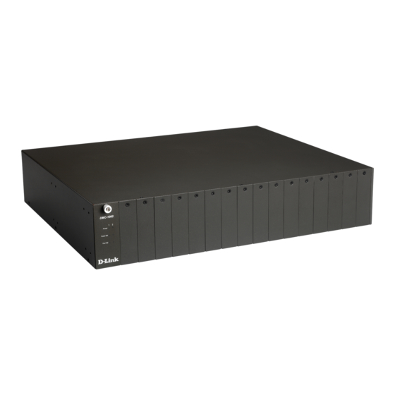
19” Media Converter Chassis System The chassis equipped with two power supplies and sixteen media converters The chassis system ships with only one power supply. Attention! Proprietary media converters and a second power supply are not included! -
Page 5: Product Features
RODUCT EATURES This chapter describes the features of the Media Converter Chassis System. Product Features Plug-and-Play House up to Sixteen media converters Front panel LEDs for bay and fan power status Standard 19” rackmountable size, 2U Non-stop operation & minimal downtime The following items are designed to be hot swappable to allow easy and quick replacement: - Media converters... -
Page 6: Unpacking And Installation
NPACKING AND NSTALLATION This chapter provides unpacking and installation information for the Switch. To avoid causing any damage to the Switch, we recommend that you read this chapter carefully before starting installation. Unpacking When unpacking the product package, you shall find these items listed below. -
Page 7: Deciding How To Install The System
degrees Fahrenheit (0 to 40 degrees Celsius). The relative humidity should be less than 90 percent, non-condensing. Surrounding electrical devices should not exceed the electromagnetic field (RFC) standards for IEC 801-3, Level 2 (3V/M) field strength. Make sure that the equipment receives adequate ventilation at the rear. -
Page 8: Mounted To 19-Inch Standard Rack
.Mounted to 19-inch standard rack Use the rackmount brackets and screws to install the chassis into any EIA 19” standard rack. Step 1: Attach the brackets to each side of the chassis. Apply four screws to each side and secure them tightly. Step 2: Carefully position the chassis into the rack. -
Page 9: Installing Media Converter
.Installing Media Converter The chassis is equipped with sixteen media converter carriers, each of which is fitted into bays of the chassis. Step 1: To install a media converter module onto the chassis, you have to unscrew the bay cover from the desired bay first. Step 2: Unscrew the hand screw counter clockwise by using hand or screwdriver and pull out the media converter out the carrier as shown below. -
Page 10: Connecting To Power (Power Supply)
Connecting to Power (Power Supply) The chassis ships with only one power supply, and a second power supply option is at your discretion. When the chassis is equipped with two power supplies, you can have the following advanced performance. ♦ Hot Swappable –... -
Page 11: Installing And Removing The Power Supply
Step 1: Connect the supplied AC power cord to the back of the chassis. Step 2: Attach the plug into a standard AC outlet with a voltage range from 100~240Vac. Step 3: Turn on the chassis system by flipping the switch beside the receptacle to ON position. -
Page 12: Understanding Led Indicators
LED I NDERSTANDING NDICATORS The front panel LEDs provide instant status feedback, and, helps monitor and troubleshoot when needed. Front Panel There is an array of LED indicators, which provides you with instant feedback on the status of the power and the fan. DMC-1000 Power and Fan LED 1 / 2... -
Page 13: Technical Specifications
ECHNICAL PECIFICATIONS Chassis System Sixteen bays for housing up to sixteen Capacity media converters Material Steel power supply provided, hot- swappable Power *A second power supply for load-sharing is optional, also hot-swappable Two fans mounted together with the Cooling power supply or alone at the rear 2 LEDs for fan status 2 LEDs for power feeding in status Indicators... - Page 14 Rated 12Vdc Voltage Speed 3200 RPM +/- 250 RPM Air Delivery 42.5 CFM per min. Noise Level 36.5dB(A) Bearing Precise ball bearing system System Dimensions 80 × 80 × 25 mm Power Supply AC inputs: 100 to 240 VAC, universal power supply Power Consumption...