Table of Contents
Advertisement
Advertisement
Table of Contents

Related Manuals for Asus P5B-PLUS


Summary of Contents for Asus P5B-PLUS
- Page 1 P5B-Plus Series...
- Page 2 Product warranty or service will not be extended if: (1) the product is repaired, modified or altered, unless such repair, modification of alteration is authorized in writing by ASUS; or (2) the serial number of the product is defaced or missing.
-
Page 3: Table Of Contents
ASUS AI Lifestyle features ..........1-4 1.3.3 ASUS Special features ........... 1-6 1.3.4 ASUS Intelligent Overclocking features ......1-6 1.3.5 ASUS features and the supporting OS ......1-7 Chapter 2: Hardware information Before you proceed ..............2-1 Motherboard overview ..............2-2 2.2.1 Placement direction ............ - Page 4 4.1.1 ASUS Update utility ............4-1 4.1.2 Creating a bootable floppy disk ........4-4 4.1.3 ASUS EZ Flash 2 utility ........... 4-5 4.1.4 AFUDOS utility ..............4-6 4.1.5 ASUS CrashFree BIOS 3 utility ........4-8 BIOS setup program ..............4-9 4.2.1...
- Page 5 4.6.2 Boot Settings Configuration .......... 4-32 4.6.3 Security ................. 4-34 Tools menu ................. 4-36 4.7.1 ASUS EZ Flash 2 ............4-36 4.7.2 ASUS O.C. Profile ............4-37 Exit menu ..................4-38 Chapter 5: Software support Installing an operating system ........... 5-1 Support CD information ..............
- Page 6 AI Remote ..............5-24 5.3.10 SoundMAX High Definition Audio utility ....... 5-32 ® Windows Vista feature ............... 5-37 5.4.1 ASAP (ASUS Accelerated Propeller) ......5-37 RAID configurations ..............5-38 5.5.1 RAID definitions ............5-38 5.5.2 Installing Serial ATA hard disks ........5-39 5.5.3 Intel RAID configurations ..........
-
Page 7: Notices
Notices Federal Communications Commission Statement This device complies with Part 15 of the FCC Rules. Operation is subject to the following two conditions: • This device may not cause harmful interference, and • This device must accept any interference received including interference that may cause undesired operation. -
Page 8: Safety Information
Safety information Electrical safety • To prevent electrical shock hazard, disconnect the power cable from the electrical outlet before relocating the system. • When adding or removing devices to or from the system, ensure that the power cables for the devices are unplugged before the signal cables are connected. -
Page 9: About This Guide
Refer to the following sources for additional information and for product and software updates. ASUS websites The ASUS website provides updated information on ASUS hardware and software products. Refer to the ASUS contact information. Optional documentation Your product package may include optional documentation, such as warranty flyers, that may have been added by your dealer. -
Page 10: Conventions Used In This Guide
Conventions used in this guide To make sure that you perform certain tasks properly, take note of the following symbols used throughout this manual. DANGER/WARNING: Information to prevent injury to yourself when trying to complete a task. CAUTION: Information to prevent damage to the components when trying to complete a task. -
Page 11: P5B-Plus Series Specifications Summary
® ® ® Compatible with Intel 05B/05A/06 processors ® Intel Hyper-Threading Technology ready ® * Refer to www.asus.com for Intel CPU support list Chipset Intel P965 / ICH8R with Intel Fast Memory Access ® ® Technology System Bus 1066 / 800 / 533 MHz Memory 4 x DIMM, max. - Page 12 TPM Support (The TPM module is purchased separately) * AI Remote, AP Trigger and TPM can run both in Windows Vista and Windows XP. * AI Remote, ASAP and AP Trigger are for P5B-Plus Vista Edition only. ASUS Quiet Thermal Solution:...
- Page 13 Other Features ASUS MyLogo2™ BIOS Features 8 Mb Flash ROM, AMI BIOS, PnP, DMI2.0, WfM2.0, SM BIOS 2.3, ACPI 2.0a, ASUS EZ Flash 2, ASUS CrashFree BIOS 3 Internal I/O Connectors 3 x USB connectors support additional 6 USB ports (4...
-
Page 15: Chapter 1: Product Introduction
This chapter describes the motherboard features and the new technologies it supports. Product introduction... - Page 16 Chapter summary Welcome! ..................1-1 Package contents ................. 1-1 Special features ................1-2 ASUS P5B-PLUS Series...
-
Page 17: Welcome
® The motherboard delivers a host of new features and latest technologies, making it another standout in the long line of ASUS quality motherboards! Before you start installing the motherboard, and hardware devices on it, check the items in your package with the list below. -
Page 18: Special Features
Green ASUS This motherboard and its packaging comply with the European Union’s Restriction on the use of Hazardous Substances (RoHS). This is in line with the ASUS vision of creating environment-friendly and recyclable products/packaging to safeguard consumers’ health while minimizing the impact on the environment. - Page 19 192KHz/24-bit audio output, jack-sensing feature, retasking functions and multi- streaming technology that simultaneously sends different audio streams to different destinations. You can now talk to your partners on the headphone while playing multi-channel network games. See pages 2-24 to 2-25 for details. ASUS P5B-Plus Series...
-
Page 20: Asus Ai Lifestyle Unique Features
The TPM meets the Windows Vista BitLocker™ Drive Encryption hardware requirement for a more secure working environment. The TPM module is purchased separately. Use the ASUS TPM module ONLY! ASUS Quiet Thermal Solution ASUS Quiet Thermal solution makes system more stable and enhances the overclocking capability. -
Page 21: Asus Crystal Sound
See page 5-36 for details. ASUS EZ DIY ASUS EZ DIY feature collection provides you easy ways to install computer components, update the BIOS or back up your favorite settings. ASUS Q-Connector ASUS Q-Connector allows you to easily connect or disconnect the chassis front panel cables to the motherboard. -
Page 22: Asus Special Features
1.3.4 ASUS Intelligent Overclocking features AI NOS™ (Non-Delay Overclocking System) The patented ASUS Non-delay Overclocking System™ (AI NOS™) technology auto-detects the CPU loading and dynamically overclocks the CPU speed when needed. Unlike other dynamic overclocking techniques, AI NOS™ reacts much faster to satisfy your need for speed. -
Page 23: Asus Features And The Supporting Os
1.3.5 ASUS features and the supporting OS Refer to the following table for the OS that supports ASUS features. Win 2000 XP 32bit XP 64bit Vista 32bit Vista 64bit AI Remote AP Trigger ASAP Function as USB flash only AI NOS... - Page 24 Chapter 1: Product Introduction...
-
Page 25: Chapter 2: Hardware Information
This chapter lists the hardware setup procedures that you have to perform when installing system components. It includes description of the jumpers and connectors on the motherboard. Hardware information... - Page 26 Chapter summary Before you proceed ..............2-1 Motherboard overview ..............2-2 Central Processing Unit (CPU) ........... 2-6 System memory ................. 2-13 Expansion slots ................2-19 Jumper ..................2-22 Connectors ................. 2-24 ASUS P5B-Plus Series...
-
Page 27: Before You Proceed
The illustration below shows the location of the onboard LED. SB_PWR Standby Powered P5B-PLUS Onboard LED Power ASUS P5B-Plus Series... -
Page 28: Motherboard Overview
Motherboard overview Before you install the motherboard, study the configuration of your chassis to ensure that the motherboard fits into it. Make sure to unplug the power cord before installing or removing the motherboard. Failure to do so can cause you physical injury and damage motherboard components. -
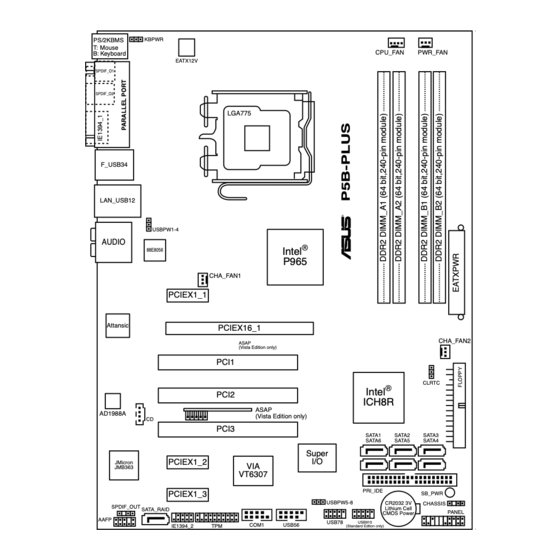
Page 29: Motherboard Layout
PRI_IDE PCIEX1_3 SB_PWR USBPW5-8 CR2032 3V CHASSIS SPDIF_OUT Lithium Cell SATA_RAID PANEL CMOS Power AAFP USB78 USB910 COM1 USB56 IE1394_2 (Standard Edtion only) Refer to 2.7 Connectors for more information about rear panel connectors and internal connectors. ASUS P5B-Plus Series... -
Page 30: Layout Contents
2.2.4 Layout contents Slots Page DDR2 DIMM slots 2-13 PCI slots 2-21 PCI Express x 1 slots 2-21 PCI Express x16 slot 2-21 Jumper Page Clear RTC RAM (3-pin CLRTC) 2-22 USB device wake-up (3-pin USBPW1-4, 3-pin USBPW5-8) 2-23 Keyboard power (3-pin KBPWR) 2-23 Rear panel connectors Page... - Page 31 Front panel audio connector (10-1 pin AAFP) 2-33 Optical drive audio connector (4-pin CD) 2-34 Digital audio connector (4-1 pin SPDIF) 2-34 Serial port connector (10-1 pin COM1) 2-35 TPM connector (20-1 pin TPM) 2-35 System panel connector (20-8 pin PANEL) 2-36 ASUS P5B-Plus Series...
-
Page 32: Central Processing Unit (Cpu)
ASUS will shoulder the cost of repair only if the damage is shipment/transit-related. • Keep the cap after installing the motherboard. ASUS will process Return Merchandise Authorization (RMA) requests only if the motherboard comes with the cap on the LGA775 socket. -
Page 33: Installing The Cpu
Installing the CPU To install a CPU: Locate the CPU socket on the motherboard. P5B-PLUS CPU Socket 775 Before installing the CPU, make sure that the cam box is facing towards you and the load lever is on your left. - Page 34 Lift the load plate with your thumb and forefinger to a 100º angle (A), then push the PnP cap from the load plate window to remove (B). Load plate Alignment key Position the CPU over the socket, making sure that the gold triangle is on the bottom-left corner of the socket then fit the socket...
-
Page 35: Installing The Cpu Heatsink And Fan
CPU fan connector. Motherboard hole Fastener Narrow end of the groove Make sure to orient each fastener with the narrow end of the groove pointing outward. (The photo shows the groove shaded for emphasis.) ASUS P5B-Plus Series... - Page 36 Connect the CPU fan cable to the connector on the motherboard labeled CPU_FAN. CPU_FAN P5B-PLUS CPU fan connector DO NOT forget to connect the CPU fan connector! Hardware monitoring errors can occur if you fail to plug this connector. 2-10...
-
Page 37: Uninstalling The Cpu Heatsink And Fan
Rotate each fastener counterclockwise. Pull up two fasteners at a time in a diagonal sequence to disengage the heatsink and fan assembly from the motherboard. Carefully remove the heatsink and fan assembly from the motherboard. ASUS P5B-Plus Series 2-11... - Page 38 Rotate each fastener clockwise to ensure correct orientation when reinstalling. Narrow end of the groove The narrow end of the groove should point outward after resetting. (The photo shows the groove shaded for emphasis.) Refer to the documentation in the boxed or stand-alone CPU fan package for detailed information on CPU fan installation.
-
Page 39: System Memory
240-pin footprint compared to the 184-pin DDR DIMM. DDR2 DIMMs are notched differently to prevent installation on a DDR DIMM socket. The figure illustrates the location of the DDR2 DIMM sockets: P5B-PLUS 240-pin DDR2 DIMM sockets Channel Sockets Channel A... - Page 40 • If you install four 1 GB memory modules, the system may detect less than 3 GB of total memory because of address space allocation for other critical functions. This limitation applies to Windows XP 32-bit version operating system since it does not support PAE (Physical Address Extention) mode. •...
- Page 41 P5B-Plus Series Motherboard Qualified Vendors Lists (QVL) DDR2-800MHz capability DIMM socket support (3Dmark) Size Vendor Chip No. Part No. 512MB KINGSTON K4T51083QC KVR800D2N5/512 1024MB KINGSTON Heat-Sink Package KHX6400D2LL/1G 1024MB KINGSTON Heat-Sink Package KHX6400D2LLK2/1GN 256MB Qimonda HYB18T512160BF-25F HYS64T32000HU-25F-B 512MB Qimonda HYB18T512800BF25F...
- Page 42 DDR2-667MHz capability DIMM socket support (3Dmark) Size Vendor Chip No. Part No. 256MB KINGSTON HYB18T256800AF3 KVR667D2N5/256 512MB KINGSTON D6408TEBGGL3U KVR667D2N5/512 1024MB KINGSTON D6408TEBGGL3U KVR667D2N5/1G 256MB Qimonda HYB18T512160AF-3S HYS64T32000HU-3S-A 512MB Qimonda HYB18T512800AF3S HYS64T64000HU-3S-A 1024MB Qimonda HYB18T512800AF3S HYS64T128020HU-3S-A 256MB Qimonda HYB18T256800AF3S(ECC) HYS72T32000HU-3S-A 512MB Qimonda HYB18T512800AF3S(ECC)
- Page 43 Supports one pair of modules inserted into either Channel A or Channel B as one pair of Dual- channel memory configuration. Supports four modules inserted into the yellow and black slots as two pairs of Dual-channel memory configuration. Visit the ASUS website for the latest DDR2-800/667/533 MHz QVL. ASUS P5B-Plus Series 2-17...
-
Page 44: Installing A Dimm
2.4.3 Installing a DIMM Unplug the power supply before adding or removing DIMMs or other system components. Failure to do so can cause severe damage to both the motherboard and the components. To install a DIMM: DDR2 DIMM notch Unlock a DIMM socket by pressing the retaining clips outward. -
Page 45: Expansion Slots
IRQ” or that the cards do not need IRQ assignments. Otherwise, conflicts will arise between the two PCI groups, making the system unstable and the card inoperable. Refer to the table on the next page for details. ASUS P5B-Plus Series 2-19... -
Page 46: Interrupt Assignments
2.5.3 Interrupt assignments Standard interrupt assignments IRQ Priority Standard Function System Timer Keyboard Controller — Re-direct to IRQ#9 IRQ holder for PCI steering* Communications Port (COM1)* IRQ holder for PCI steering* Floppy Disk Controller Printer Port (LPT1)* System CMOS/Real Time Clock ACPI* SMBus Controller* IRQ holder for PCI steering*... -
Page 47: Pci Slots
PCI Express x1 slot. 2.5.6 PCI Express x16 slot This motherboard has one PCI Express x16 slots that support PCI Express x16 graphic cards complying with the PCI Express specifications. ASUS P5B-Plus Series 2-21... -
Page 48: Jumper
Removing the cap will cause system boot failure! CLRTC Normal Clear RTC P5B-PLUS Clear RTC RAM (Default) • You do not need to clear the RTC when the system hangs due to overclocking. For system failure due to overclocking, use the C.P.R. (CPU Parameter Recall) feature. - Page 49 USBPW1-4 +5VSB (Default) USBPW5-8 +5VSB (Default) P5B-PLUS USB device wake-up • The USB device wake-up feature requires a power supply that can provide 500mA on the +5VSB lead for each USB port; otherwise, the system will not power up. ®...
-
Page 50: Connectors
Connectors 2.7.1 Rear panel connectors PS/2 mouse port (green). This port is for a PS/2 mouse. Parallel port. This 25-pin port connects a parallel printer, a scanner, or other devices. IEEE 1394a port. This 6-pin IEEE 1394a port provides high-speed connectivity for audio/video devices, storage peripherals, PCs, or portable devices. - Page 51 0, RAID 1, or JBOD set through the onboard JMicron SATA RAID controller. The external SATA port supports external Serial ATA 3.0 Gb/s devices. Longer cables support higher power requirements to deliver signal up to two meters away, and enables improved hot-swap function. ASUS P5B-Plus Series 2-25...
- Page 52 • Before creating a RAID set using Serial ATA hard disks, make sure that you have connected the Serial ATA signal cable and installed Serial ATA hard disk drives; otherwise, you cannot enter the JMicron RAID utility and SATA BIOS setup during POST. •...
-
Page 53: Internal Connectors
FDD cable with a covered Pin 5. FLOPPY NOTE: Orient the red markings on the floppy ribbon cable to PIN 1. P5B-PLUS Floppy disk drive connector ® JMicron JMB363 Serial ATA RAID connector (7-pin SATA_RAID) This connector is for a Serial ATA signal cable. This connector supports a... -
Page 54: Sata1 Sata2
SATA3 SATA6 SATA5 SATA4 SATA6 SATA5 SATA4 P5B-PLUS SATA connectors P5B-PLUS SATA connectors ® ® • You must install Windows 2000 Service Pack 4 or the Windows Service Pack 1 before using Serial ATA hard disk drives. The Serial ATA RAID feature (RAID 0/RAID 1/RAID 5/RAID 10) is available only if you are ®... - Page 55 If any device jumper is set as “Cable-Select,” make sure all other device jumpers have the same setting. PRI_IDE NOTE: Orient the red markings (usually zigzag) on the IDE P5B-PLUS IDE connector ribbon cable to PIN 1. ASUS P5B-Plus Series 2-29...
- Page 56 Never connect a 1394 cable to the USB connectors. Doing so will damage the motherboard! Connect the USB cable to ASUS Q-Connector (USB, blue) first, and then install the Q-Connector (USB) to the USB56 connector onboard. IEEE 1394a port connector (10-1 pin IE1394_2) This connector is for a IEEE 1394a port.
- Page 57 Never connect a USB cable to the IEEE 1394a connector. Doing so will damage the motherboard! You can connect the 1394 cable to ASUS Q-Connector (1394, red) first, and then install the Q-Connector (1394) to the 1394 connector onboard. CPU, chassis, power fan connectors (4-pin CPU_FAN, 3-pin CHA_FAN1, 3-pin CHA_FAN2, 3-pin PWR_FAN) The fan connectors support cooling fans of 350 mA ~ 2000 mA (24 W max.)
- Page 58 CHASSIS (Default) P5B-PLUS Chassis intrusion connector ATX power connectors (24-pin EATXPWR, 4-pin EATX12V) These connectors are for ATX power supply plugs. The power supply plugs are designed to fit these connectors in only one orientation. Find the proper orientation and push down firmly until the connectors completely fit.
- Page 59 AAFP HD Audio-compliant Legacy AC 97 audio pin definition pin definition P5B-PLUS Analog front panel connector • We recommend that you connect a high-definition front panel audio module to this connector to avail of the motherboard’s high-definition audio capability. •...
- Page 60 Ground (black) Ground Left Audio Channel P5B-PLUS Internal audio connector 12. Digital audio connector (4-1 pin SPDIF) This connector is for an additional Sony/Philips Digital Interface (S/PDIF) port(s). Connect the S/PDIF Out module cable to this connector, then install the module to a slot opening at the back of the system chassis.
- Page 61 A TPM system also helps enhance network security, protects digital identities, and ensures platform integrity. P5B-PLUS TPM connector The TPM module is purchased separately. Use the ASUS TPM module ONLY! ASUS P5B-Plus Series 2-35...
-
Page 62: System Panel Connector
PANEL RESET IDE_LED PWRSW Requires an ATX power supply. P5B-PLUS System panel connector • System power LED (2-pin PLED) This 2-pin connector is for the system power LED. Connect the chassis power LED cable to this connector. The system power LED lights up when you turn on the system power, and blinks when the system is in sleep mode. - Page 63 ASUS Q-Connector (system panel) You can use the ASUS Q-Connector to connect/disconnect chassis front panel cables in a few steps. Refer to the instructions below to install the ASUS Q- Connector. Connect the front panel cables to the ASUS Q-Connector.
- Page 64 2-38 Chapter 2: Hardware information...
-
Page 65: Chapter 3: Powering Up
This chapter describes the power up sequence, the vocal POST messages, and ways of shutting down the system. Powering up... - Page 66 Chapter summary Starting up for the first time ............3-1 Turning off the computer ............. 3-2 ASUS P5B-Plus Series...
-
Page 67: Starting Up For The First Time
One continuous beep followed by three No VGA detected short beeps One continuous beep followed by four Hardware component failure short beeps At power on, hold down the <Delete> key to enter the BIOS Setup. Follow the instructions in Chapter 4. ASUS P5B-Plus Series... -
Page 68: Using The Os Shut Down Function
Turning off the computer 3.2.1 Using the OS shut down function ® If you are using Windows 2000: Click the Start button then click Shut Down. Make sure that the Shut Down option button is selected, then click the OK button to shut down the computer. -
Page 69: Chapter 4: Bios Setup
This chapter tells how to change the system settings through the BIOS Setup menus. Detailed descriptions of the BIOS parameters are also provided. BIOS setup... - Page 70 Chapter summary Managing and updating your BIOS ..........4-1 BIOS setup program ..............4-9 Main menu .................. 4-12 Advanced menu ................. 4-16 Power menu ................4-27 Boot menu .................. 4-31 Tools menu ................. 4-36 Exit menu ..................4-38 ASUS P5B-Plus Series...
-
Page 71: Managing And Updating Your Bios
ASUS Update (Updates the BIOS in Windows environment.) ® ASUS EZ Flash 2 (Updates the BIOS using a floppy disk or USB flash disk.) ASUS AFUDOS (Updates the BIOS using a bootable floppy disk) ASUS CrashFree BIOS 3 (Recovers the BIOS using a bootable floppy disk, USB flash disk or the motherboard support CD when the BIOS file fails or gets corrupted.) - Page 72 To update the BIOS through the Internet: Launch the ASUS Update utility from the Windows desktop by clicking Start ® > Programs > ASUS > ASUSUpdate > ASUSUpdate. The ASUS Update main window appears. Select Update BIOS from the Select the ASUS FTP site nearest...
- Page 73 To update the BIOS through a BIOS file: Launch the ASUS Update utility from the Windows desktop by clicking Start ® > Programs > ASUS > ASUSUpdate > ASUSUpdate. The ASUS Update main window appears. Select Update BIOS from a file option from the drop-down menu, then click Next.
-
Page 74: Creating A Bootable Floppy Disk
4.1.2 Creating a bootable floppy disk Do either one of the following to create a bootable floppy disk. DOS environment a. Insert a 1.44MB floppy disk into the drive. b. At the DOS prompt, type format A:/S then press <Enter>. Windows XP environment ®... -
Page 75: Asus Ez Flash 2 Utility
4.1.3 ASUS EZ Flash 2 utility The ASUS EZ Flash 2 feature allows you to update the BIOS without having to go through the long process of booting from a floppy disk and using a DOS-based utility. The EZ Flash 2 utility is built-in the BIOS chip so it is accessible by pressing <Alt>... -
Page 76: Afudos Utility
Updating the BIOS file To update the BIOS file using the AFUDOS utility: Visit the ASUS website (www.asus.com) and download the latest BIOS file for the motherboard. Save the BIOS file to a bootable floppy disk. Chapter 4: BIOS setup... - Page 77 A:\>afudos /iP5BP.ROM The utility verifies the file and starts updating the BIOS. A:\>afudos /iP5BP.ROM AMI Firmware Update Utility - Version 1.19(ASUS V2.07(03.11.24BB)) Copyright (C) 2002 American Megatrends, Inc. All rights reserved. WARNING!! Do not turn off power during flash BIOS Reading file ..done Reading flash ..
-
Page 78: Asus Crashfree Bios 3 Utility
4.1.5 ASUS CrashFree BIOS 3 utility The ASUS CrashFree BIOS 3 is an auto recovery tool that allows you to restore the BIOS file when it fails or gets corrupted during the updating process. You can update a corrupted BIOS file using the motherboard support CD, the floppy disk, or the USB flash disk that contains the updated BIOS file. -
Page 79: Bios Setup Program
The BIOS setup screens shown in this section are for reference purposes only, and may not exactly match what you see on your screen. • Visit the ASUS website (www.asus.com) to download the latest BIOS file for this motherboard. ASUS P5B-Plus Series... -
Page 80: Bios Menu Screen
4.2.1 BIOS menu screen Menu items Menu bar Configuration fields General help BIOS SETUP UTILITY Main Advanced Power Boot Tools Exit Use [ENTER], [TAB] System Time [10:55:25] or [SHIFT-TAB] to System Date [Mon 07/24/2006] select a field. Legacy Diskette A [1.44M, 3.5 in] Use [+] or [-] SATA 1... -
Page 81: Menu Items
<Page Up> /<Page Down> keys to display the other items on the screen. 4.2.9 General help Pop-up window At the top right corner of the menu screen Scroll bar is a brief description of the selected item. ASUS P5B-Plus Series 4-11... -
Page 82: Main Menu
Main menu When you enter the BIOS Setup program, the Main menu screen appears, giving you an overview of the basic system information. Refer to section 4.2.1 BIOS menu screen for information on the menu screen items and how to navigate through them. BIOS SETUP UTILITY Main Advanced... -
Page 83: Sata 1-6
When set to [Disabled], the data transfer from and to the device occurs one sector at a time. Configuration options: [Disabled] [Auto] PIO Mode [Auto] Selects the PIO mode. Configuration options: [Auto] [0] [1] [2] [3] [4] ASUS P5B-Plus Series 4-13... -
Page 84: Ide Configuration
DMA Mode [Auto] Selects the DMA mode. Configuration options: [Auto] [SWDMA0] [SWDMA1] [SWDMA2] [MWDMA0] [MWDMA1] [MWDMA2] [UDMA0] [UDMA1] [UDMA2] [UDMA3] [UDMA4] [UDMA5] SMART Monitoring [Auto] Sets the Smart Monitoring, Analysis, and Reporting Technology. Configuration options: [Auto] [Disabled] [Enabled] 32Bit Data Transfer [Enabled] Enables or disables 32-bit data transfer. -
Page 85: System Information
Select Screen Select Item General Help Save and Exit Exit v02.58 (C)Copyright 1985-2006, American Megatrends, Inc. AMI BIOS Displays the auto-detected BIOS information. Processor Displays the auto-detected CPU specification. System Memory Displays the auto-detected system memory. ASUS P5B-Plus Series 4-15... -
Page 86: Advanced Menu
Loads the optimal settings for the system. Standard Loads the standard settings for the system. AI N.O.S. The ASUS Non-delay Overclocking System feature intelligently determines the system load and automatically boosts the performance for the most demanding tasks. 4-16 Chapter 4: BIOS setup... - Page 87 Allows you to synchronize the PCI frequency with the PCI Express or CPU frequency. Configuration options: [Auto] [33.33MHz] Spread Spectrum [Auto] Allows you to enable or disable the clock generator spread spectrum. Configuration options: [Disabled] [Enabled] [Auto] ASUS P5B-Plus Series 4-17...
- Page 88 The following items also appear when the AI Tuning item is set to [AI NOS]. Memory Voltage [Auto] Allows you to select the DDR2 reference voltage. Configuration options: [Auto] [1.80V] [1.85V] [1.90V]~[2.40V] [2.45V] Refer to the DDR2 documentation before adjusting the memory voltage. Setting a very high memory voltage may damage the memory module(s)! CPU VCore Voltage [Auto] Allows you to select the CPU VCore voltage.
-
Page 89: Usb Configuration
USB Functions [Enabled] Allows you to enable or disable the USB functions. Configuration options: [Disabled] [Enabled] ASAP (ASUS Accelerated Propeller) will function only when the USB Functions item is set to [Enabled]. ASAP [Disabled] Allows you to enable or disable the ASAP function. -
Page 90: Tpm Configuration
BIOS EHCI Hand-off [Enabled] Allows you to enable support for operating systems without an EHCI hand-off feature. Configuration options: [Disabled] [Enabled] 4.4.3 TPM Configuration The items in this menu allows you to configure the TPM functions. Select an item then press <Enter> to display the configuration options. BIOS SETUP UTILITY Advanced TPM Configuration... -
Page 91: Cpu Configuration
Allows you to set the ratio between the CPU Core Clock and the FSB Frequency. Use <+> and <-> to adjust the value. Configuration options: [14] [15]~[23] [24] C1E Support [Enabled] Allows you to enable or disable C1E Support. Configuration options: [Disabled] [Enabled] ASUS P5B-Plus Series 4-21... - Page 92 Max CPUID Value Limit [Disabled] Setting this item to [Enabled] allows legacy operating systems to boot even without support for CPUs with extended CPUID functions. Configuration options: [Disabled] [Enabled] Vanderpool Technology [Enabled] Configuration options: [Enabled] [Disabled] CPU TM function [Enabled] Configuration options: [Disabled] [Enabled] Execute Disable Bit [Enabled] Allows you to enable or disable the No-Execution Page Protection Technology.
-
Page 93: Chipset
Configuration options: [Disable] [Auto] [Fast] [Faster] Initiate Graphic Adapter [PEG/PCI] Allows you to decide which graphics controller to use as the primary boot device. Configuration options: [PCI/PEG] [PEG/PCI] PEG Force x1 [Disabled] Configuration options: [Enabled] [Disabled] ASUS P5B-Plus Series 4-23... -
Page 94: Onboard Devices Configuration
4.4.6 Onboard Devices Configuration BIOS SETUP UTILITY Advanced Configure Win627EHF Super IO Chipset Enable or Disable High Definition Audio HD Audio Controller [Enabled] Controller Front Panel Support Type [AC97] Onboard 1394 Controller [Enabled] Onboard PCIE GbE LAN [Enabled] LAN Option ROM [Disabled] JMicron SATA/PATA Controller [Enabled]... - Page 95 Configuration options: [Normal] [Bi-Directional] [EPP] [ECP] ECP Mode DMA Channel [DMA3] Allows you to select the Parallel Port ECP DMA. Configuration options: [DMA0] [DMA1] [DMA3] Parallel Port IRQ [IRQ7] Allows you to select the Parallel Port IRQ. Configuration options: [IRQ5] [IRQ7] ASUS P5B-Plus Series 4-25...
-
Page 96: Pcipnp
4.4.7 PCIPnP The PCIPnP menu items allow you to change the advanced settings for PCI/PnP devices. The menu includes setting IRQ and DMA channel resources for either PCI/PnP or legacy ISA devices, and setting the memory size block for legacy ISA devices. -
Page 97: Power Menu
Allows you to enable or disable the Advanced Configuration and Power Interface (ACPI) support in the Advanced Programmable Interrupt Controller (APIC). When set to [Enabled], the ACPI APIC table pointer is included in the RSDT pointer list. Configuration options: [Disabled] [Enabled] ASUS P5B-Plus Series 4-27... -
Page 98: Apm Configuration
4.5.5 APM Configuration BIOS SETUP UTILITY Power APM Configuration <Enter> to select whether or not to restart the system Restore on AC Power Loss [Power Off] after AC power loss. Power On By RTC Alarm [Disabled] Power On By External Modems [Disabled] Power On By PCI Devices [Disabled]... -
Page 99: Hardware Monitor
(RPM). If the fan is not connected to the motherboard, the field shows [N/A]. CPU Q-Fan Control [Disabled] Allows you to enable or disable the CPU Q-Fan controller. Configuration options: [Disabled] [Enabled] ASUS P5B-Plus Series 4-29... - Page 100 The CPU Q-Fan Profile item appears when you enable the CPU Q-Fan Control feature. CPU Q-Fan Profile [Optimal] Allows you to set the appropriate performance level of the CPU Q-Fan. When set to [Optimal], the CPU fan automatically adjusts depending on the CPU temperature.
-
Page 101: Boot Menu
These items specify the boot device priority sequence from the available devices. The number of device items that appears on the screen depends on the number of devices installed in the system. Configuration options: [1st FLOPPY DRIVE] [Hard Drive] [ATAPI CD-ROM] [Disabled] ASUS P5B-Plus Series 4-31... -
Page 102: Boot Settings Configuration
This allows you to enable or disable the full screen logo display feature. Configuration options: [Disabled] [Enabled] Set this item to [Enabled] to use the ASUS MyLogo2™ feature. AddOn ROM Display Mode [Force BIOS] Sets the display mode for the option ROM. - Page 103 When set to [Enabled], the system displays the message “Press DEL to run Setup” during POST. Configuration options: [Disabled] [Enabled] Interrupt 19 Capture [Disabled] When set to [Enabled], this function allows the option ROMs to trap Interrupt 19. Configuration options: [Disabled] [Enabled] ASUS P5B-Plus Series 4-33...
-
Page 104: Security
4.6.3 Security The Security menu items allow you to change the system security settings. Select an item then press <Enter> to display the configuration options. BIOS SETUP UTILITY Boot Security Settings <Enter> to change password. Supervisor Password : Not Installed <Enter>... -
Page 105: Change User Password
Password Check [Setup] When set to [Setup], BIOS checks for user password when accessing the Setup utility. When set to [Always], BIOS checks for user password both when accessing Setup and booting the system. Configuration options: [Setup] [Always] ASUS P5B-Plus Series 4-35... -
Page 106: Tools Menu
4.7.1 ASUS EZ Flash 2 Allows you to run ASUS EZ Flash 2. When you press <Enter>, a confirmation message appears. Use the left/right arrow key to select between [Yes] or [No], then press <Enter> to confirm your choice. Please see page 4-5, section 4.1.3 for details. -
Page 107: Asus O.c. Profile
This function can support devices such as USB flash disks or floppy disks with FAT 32/16 format and single partition only. • DO NOT shut down or reset the system while updating the BIOS to prevent the system boot failure! ASUS P5B-Plus Series 4-37... -
Page 108: Exit Menu
Exit menu The Exit menu items allow you to load the optimal or failsafe default values for the BIOS items, and save or discard your changes to the BIOS items. BIOS SETUP UTILITY Main Advanced Power Boot Tools Exit Exit Options Exit system setup after saving the Exit &... -
Page 109: Chapter 5: Software Support
This chapter describes the contents of the support CD that comes with the motherboard package. Software support... - Page 110 Chapter summary Installing an operating system ........... 5-1 Support CD information .............. 5-1 Software information ..............5-9 Windows Vista feature ............... 5-37 RAID configurations ..............5-38 Creating a RAID driver disk ............5-55 ASUS P5B-Plus Series...
-
Page 111: Installing An Operating System
The contents of the support CD are subject to change at any time without notice. Visit the ASUS website(www.asus.com) for updates. 5.2.1 Running the support CD Place the support CD to the optical drive. The CD automatically displays the Drivers menu if Autorun is enabled in your computer. -
Page 112: Drivers Menu
Installs all of the drivers through the Installation Wizard. Intel Chipset Inf Update Program Installs the Intel chipset Inf update program. ® ASUS AI Remote Installs ASUS AI Remote utility. SoundMAX ADI1988 Audio Driver Installs the SoundMAX ADI1988 audio driver and application. ® Attansic L1 Gigabit Ethernet Driver Installs the Attansic L1 Gigabit Ethernet driver. -
Page 113: Utilities Menu
ASUS AI Suite Install the ASUS AI Suite. ASUS Update The ASUS Update utility allows you to update the motherboard BIOS in Windows ® environment. This utility requires an Internet connection either through a network or an Internet Service Provider (ISP). - Page 114 Install the following utilities from the ASUS Superb Software Library CD if needed.. ADOBE Acrobat Reader V7.0 Installs the Adobe Acrobat Reader that allows you to open, view, and print ® ® documents in Portable Document Format (PDF). Microsoft DirectX 9.0c Installs the Microsoft DirectX 9.0c driver.
-
Page 115: Make Disk Menu
RAID/AHCI driver disk. Make Intel ICH8 32/64bit RAID/AHCI Driver Disk Allows you to create an ICH8 32/64bit RAID/AHCI driver disk. Make JMicron JMB36X 32/64bit RAID/AHCI Driver Allows you to create a JMicron JMB36X 32/64bit RAID/AHCI driver. ® ASUS P5B-Plus Series... -
Page 116: Manual Menu
Reader from the Utilities menu before opening a user manual file. ® 5.2.6 ASUS Contact information Click the Contact tab to display the ASUS contact information. You can also find this information on the inside front cover of this user guide. Chapter 5: Software support... -
Page 117: Other Information
The icons on the top right corner of the screen give additional information on the motherboard and the contents of the support CD. Click an icon to display the specified information. Motherboard Info Displays the general specifications of the motherboard. Browse this CD Displays the support CD contents in graphical format. ASUS P5B-Plus Series... -
Page 118: Technical Support Form
Technical support Form Displays the ASUS Technical Support Request Form that you have to fill out when requesting technical support. Filelist Displays the contents of the support CD in text format. Chapter 5: Software support... -
Page 119: Software Information
5.3.1 ASUS MyLogo2™ The ASUS MyLogo2™ utility lets you customize the boot logo. The boot logo is the image that appears on screen during the Power-On-Self-Tests (POST). The ASUS MyLogo2™ is automatically installed when you install the ASUS Update utility from the support CD. - Page 120 Ratio box. When the screen returns to the ASUS Update utility, flash the original BIOS to load the new boot logo. 10. After flashing the BIOS, restart the computer to display the new boot logo during POST.
-
Page 121: Pc Probe Ii
® To launch the PC Probe II from the Windows desktop, click Start > All Programs > ASUS > PC Probe II > PC Probe II v1.xx.xx. The PC Probe II main window appears. ® After launching the application, the PC Probe II icon appears in the Windows taskbar. - Page 122 Button Function Opens the Configuration window Opens the Report window Opens the Desktop Management Interface window Opens the Peripheral Component Interconnect window Opens the Windows Management Instrumentation window Opens the hard disk drive, memory, CPU usage window Shows/Hides the Preference section Minimizes the application Closes the application Sensor alert...
- Page 123 Click to the or buttons. You can also adjust increase the threshold values using the value Config window. Click to You cannot adjust the sensor decrease threshold values in a small value monitoring panel. ASUS P5B-Plus Series 5-13...
- Page 124 Monitoring sensor alert The monitor panel turns red when a component value exceeds or is lower than the threshold value. Refer to the illustrations below. Small display Large display WMI browser Click to display the WMI (Windows Management Instrumentation) browser. This ®...
- Page 125 Click a hard disk drive to display the information on the right panel. The pie chart at the bottom of the window represents the used (blue) and the available HDD space. ASUS P5B-Plus Series 5-15...
- Page 126 Memory usage The Memory tab shows both used and available physical memory. The pie chart at the bottom of the window represents the used (blue) and the available physical memory. Configuring PC Probe II Click to view and adjust the sensor threshold values. The Config window has two tabs: Sensor/Threshold and Preference.
-
Page 127: Asus Ai Suite
5.3.3 ASUS AI Suite ASUS AI Suite allows you to launch AI Gear, AI N.O.S., AI Booster, AI Nap, and Q-Fan utilities easily. Installing AI Suite To install AI Suite on your computer: Place the support CD to the optical drive. The Drivers installation tab appears if your computer has an enabled Autorun feature. - Page 128 Other feature buttons Click on right corner of the main window to open the monitor window. Displays the CPU/ system temperature, CPU/memory/PCIE voltage, and CPU/ chassis fan speed Displays the FSB/CPU frequency Click on right corner of the expanded window to switch the temperature from degrees Centigrade to degrees Fahrenheit.
-
Page 129: Asus Ai Gear
5.3.4 ASUS AI Gear ASUS AI Gear provides four system performance options that allows you to select the best performance setting for your computing needs. This easy-to-use utility adjusts the processor frequency and vCore voltage to minimize system noise and power consumption. -
Page 130: Asus Ai Nap
5.3.5 ASUS AI Nap This feature allows you to minimize the power consumption of your computer whenever you are away. Enable this feature for minimum power consumption and a more quiet system operation. After installing AI Suite from the bundled support CD, you can launch the utility by double-clicking the AI Suite icon on the Windows OS taskbar and click the AI Nap button on the AI Suite main window. -
Page 131: Asus Ai N.o.s
5.3.6 ASUS AI N.O.S. This ASUS Non-delay Overclocking System feature intelligently determines the system load and automatically boosts the performance for the most demanding tasks. After installing AI Suite from the bundled support CD, you can launch the utility by double-clicking the AI Suite icon on the Windows OS taskbar and click the AI N.O.S. -
Page 132: Asus Q-Fan
5.3.7 ASUS Q-Fan This ASUS Q-Fan Control feature allows you to set the appropriate performance level of the CPU Q-Fan or the Chassis Q-Fan for more efficient system operation. After enabling the Q-Fan function, the fans can be set to automatically adjust depending on the temperature, to decrease fan speed, or to achieve the maximum fan speed. -
Page 133: Asus Ai Booster
5.3.8 ASUS AI Booster The ASUS AI Booster application allows you to overclock the CPU speed in WIndows environment without the hassle of booting the BIOS. ® After installing AI Suite from the bundled support CD, you can launch the utility... -
Page 134: Ai Remote
5.3.9 AI Remote With the ASUS AI Remote, you can play, pause, or adjust the volume on any songs desired without leaving your sofa. Have AI Remote in your hand and do more with your PC at a distance away. -
Page 135: Software Installation
USB receiver • The valid IR function distance is 6m depending on the environment. Suggest you to aim at the IR receiver when using the ASUS AI Remote to ensure a smooth and successful operation. • These two USB ports support USB wake-up capability. So when the computer is not turned on, removing USB devices such as the ASUS IR receiver from these two ports will start up the PC. - Page 136 Activating HID-Compliant Devices Due to the limitation of the operating system, if you remove the IR receiver from the previous port and have it reinstall into the other USB port, the IR receiver will not function. To activate the HID-compliant devices again, go to Device Manager/ Power Manager and check the box of Allow this device to bring the computer out of standby.
- Page 137 ASUS AI Remote Settings After the installation of the ASUS AI Remote software, the utility screen will show up and allows you to configure the ASUS AI Remote settings. Set up the function keys following the instructions below. 1. Power On / Off Key Enable power key Click this box to enable this power button.
- Page 138 • Save after the .exe file path is directed. • If the executable file is relocated or the application is re-installed, you have to redirect the file path for a correct ASUS AI Remote operation. 5-28 Chapter 5: Software support...
- Page 139 After selecting a desired file, folder or CD-ROM, use to choose Back/OK/Cancel and then press to confirm. • For music listening, making playlists beforehand is suggested. • Press again to close the application and again to re-launch the profile menu ASUS P5B-Plus Series 5-29...
- Page 140 If you want to use the Media Control Zone to control non-default applications, such as ACDSee, you can select User Define from the drop-down menu and rename it by pressing Rename. The ASUS AI Remote software has correctly set up nine popular applications and defined the funtion buttons for your convenient operation.
- Page 141 The Function Buttons and AP Profile The ASUS AI Remote software helps you set up the correspondence between the function buttons on the remote to the function hotkeys of nine popular applications in advance and leaves five sets for User Define.
- Page 142 ® 5.3.10 SoundMAX High Definition Audio utility The ADI AD1988 High Definition Audio CODEC provides 8-channel audio ® capability through the SoundMAX audio utility with AudioESP™ software to deliver the ultimate audio experience on your PC. The software implements high quality audio synthesis/rendering, 3D sound positioning, and advanced voice-input technologies.
-
Page 143: Audio Setup Wizard
SoundMAX Control Panel. Audio Setup Wizard ® By clicking the icon from the SoundMAX control panel, you can easily configure your audio settings. Simply follow succeeding screen instructions and begin enjoying High Definition Audio. ASUS P5B-Plus Series 5-33... - Page 144 Jack configuration Adjust speaker volume This screen helps you configure your This screen helps you adjust speaker computer’s audio ports, depending on volume. Click the Test button to hear the audio devices you have installed. the changes you have made. Adjust microphone volume This screen helps you adjust microphone volume.
-
Page 145: Listening Environment Options
Click the General tab to choose your playback and recording devices, enable/ disable the AudioESP™ feature, and enable/disable digital output. Listening Environment options Click the Listening Environment tab to set up your speaker, acoustic environment, and enable/disable the Virtual Theater Surround function. ASUS P5B-Plus Series 5-35... -
Page 146: Microphone Options
Microphone options Click the Microphone tab allows you to optimize your microphone input settings. 5-36 Chapter 5: Software support... -
Page 147: Windows Vista Feature
Windows Vista feature 5.4.1 ASAP (ASUS Accelerated Propeller) This motherboard is equipped with the ASUS Accelerated Propeller (ASAP) feature. ASAP supports the Windows Vista ReadyBoost function that improves ® ™ system performance under Windows Vista. Refer to page 1-7 for the OS that ®... -
Page 148: Raid Configurations
RAID configurations The motherboard comes with the following RAID resolutions: ® • Intel ICH8R Southbridge RAID controller that allow you to configure IDE and Serial ATA hard disk drives as RAID sets. The motherboard supports the following RAID 0, 1, 5, 10. ®... -
Page 149: Installing Serial Ata Hard Disks
Select the item Onboard Serial-ATA BOOTROM, press <Enter>, then select Enabled from the options. Save your changes, then exit the BIOS Setup. Refer to the system or the motherboard user guide for details on entering and navigating through the BIOS Setup. ASUS P5B-Plus Series 5-39... -
Page 150: Intel Matrix Storage Manager Option Rom Utility
® Intel Matrix Storage Manager Option ROM Utility ® The Intel Matrix Storage Manager Option ROM utility allows you to create RAID 0, RAID 1, RAID 10 (RAID 0+1), and RAID 5 set(s) from Serial ATA hard disk drives that are connected to the Serial ATA connectors supported by the Southbridge. ®... -
Page 151: Creating A Raid 0 Set (Striped)
Select 2 to 4 disks to use in creating the volume. [↑↓]-Previous/Next [SPACE]-Selects [ENTER]-Selection Complete Use the up/down arrow key to highlight a drive, then press <Space> to select. A small triangle marks the selected drive. Press <Enter> after completing your selection. ASUS P5B-Plus Series 5-41... - Page 152 Use the up/down arrow key to select the stripe size for the RAID 0 array, then press <Enter>. The available stripe size values range from 4 KB to 128 KB. The default stripe size is 128 KB. TIP: We recommend a lower stripe size for server systems, and a higher stripe size for multimedia computer systems used mainly for audio and video editing.
-
Page 153: Creating A Raid 1 Set (Mirrored)
WARNING: ALL DATA ON SELECTED DISKS WILL BE LOST. Are you sure you want to create this volume? (Y/N): Press <Y> to create the RAID volume and return to main menu or <N> to go back to Create Volume menu. ASUS P5B-Plus Series 5-43... - Page 154 Creating a RAID 10 set (RAID 0+1) To create a RAID 10 set: From the utility main menu, select 1. Create RAID Volume, then press <Enter>. This screen appears. Intel(R) Matrix Storage Manager Option ROM v5.0.0.1032 ICH8R wRAID5 Copyright(C) 2003-05 Intel Corporation. All Rights Reserved. [ CREATE ARRAY MENU Name: Volume10...
- Page 155 [↑↓]-Change [TAB]-Next [ESC]-Previous Menu [Enter]-Select Enter a name for the RAID 5 set, then press <Enter>. When the RAID Level item is highlighted, press the up/down arrow key to select RAID 5(Parity), then press <Enter>. ASUS P5B-Plus Series 5-45...
- Page 156 The Disks item is highlighted, press <Enter> to select the hard disk drives to configure as RAID. The following pop-up screen appears. [ SELECT DISKS Port Drive Model Serial # Size Status 0 XXXXXXXXXXXX XXXXXXXX XX.XGB Non-RAID Disk 1 XXXXXXXXXXXX XXXXXXXX XX.XGB Non-RAID Disk 2 XXXXXXXXXXXX XXXXXXXX...
-
Page 157: Before Creating A Raid Set
Create a JMB363 RAID driver disk for Windows OS installation. See section 5.6 Creating a RAID driver disk for details. ® Install the JMB363 driver after the Windows OS had been installed. Always install the JMB363 driver before creating RAID sets. ASUS P5B-Plus Series 5-47... -
Page 158: Creating A Raid Set
Entering the JMB363 RAID BIOS utility During POST, press <Ctrl-J> to enter the JBM363 RAID BIOS menu. JMicron Technology Corp. PCI-to-SATA II/IDE RAID Controller BIOS v0.97 Copyright (C) 2004-2005 JMicron Technology http://www. jmicron.com HDD0 : HDS722516VLSA80 164 GB Non-RAID HDD1 : HDS722516DLA380 164 GB Non-RAID Press <Ctrl-J>... - Page 159 Key in the RAID volume capacity. Use the up/down arrow to choose the block size. The default value indicates the maximum allowed capacity. [Create New RAID] Name : JRAID Level: 0-Stripe Disks: Select Disk Block: 128 KB Size : Confirm Creation ASUS P5B-Plus Series 5-49...
- Page 160 When done, press <Enter> to confirm the creation of the RAID set. A dialogue box appears to confirm the action. Press <Y> to confirm; otherwise, press <N>. JMicron Technology Corp. PCI-to-SATA II/IDE RAID Controller BIOS v0.97 [Create New RAID] [Hard Disk Drive List] Model Name Available Type/Status...
-
Page 161: Deleting A Raid Set
ARE YOU SURE TO DELETE (Y/N)? Y Model Name RAID Level Capacity Status Members(HDDx) RDD0: JRAID 0-Stripe XXX GB Normal TAB]-Switch Window [ ↑↓ ]-Select Item [ENTER]-Action [ESC]-Exit Pressing <Y> deletes all the data in the HDDs. ASUS P5B-Plus Series 5-51... -
Page 162: Resetting Disks To Non-Raid
Resetting disks to non-RAID An HDD that has been previously configured as part of another RAID set in another platform is called a broken RAID HDD. When you install a broken RAID HDD, you cannot select this HDD when configuring a RAID set through the JMB363 utility. -
Page 163: Solving A Mirror Conflict
RAID Inside Solve Mirror Conflict Rebuild Mirror Drive Save and Exit Setup Exit Without Saving [RAID Disk Drive List] Model Name RAID Level Capacity Status Members(HDDx) RDD0: JRAID 1-Mirror XXX GB Rebuild Rebuilding... 01%, please wait... ASUS P5B-Plus Series 5-53... -
Page 164: Rebuilding A Mirror Drive
Rebuilding a Mirror Drive When one of the disks in a RAID 1 (Mirror) configuration is unplugged from the system, then plugged in again, a dialogue box appears to ask you to rebuild the Mirror drive. Press <Y> to confirm; otherwise, press <N>. This option allows you to rebuild the Mirror drive later and synchronize the data between two hard disks. -
Page 165: Creating A Raid Driver Disk
JMB36X 32/64-bit RAID Driver to create a JMicron JMB363 RAID driver disk. Insert a floppy disk into the floppy disk drive. Follow succeeding screen instructions to complete the process. Write-protect the floppy disk to avoid computer virus infection. ASUS P5B-Plus Series 5-55... - Page 166 To install the RAID driver: During the OS installation, the system prompts you to press the F6 key to install third-party SCSI or RAID driver. Press <F6> then insert the floppy disk with RAID driver into the floppy disk drive. When prompted to select the SCSI adapter to install, make sure you select Intel(R) 82801GH/GM SATA RAID Controller (Desktop ICH8R) and JMicron JMB363.
-
Page 167: Appendix: Cpu Features
The Appendix describes the CPU features and technologies that the motherboard supports. CPU features... - Page 168 Chapter summary ® Intel EM64T ..................A-1 ® Enhanced Intel SpeedStep Technology (EIST) ......A-1 ® Intel Hyper-Threading Technology ...........A-3 ASUS P5B-Plus Series...
-
Page 169: Intel ® Em64T
32-bit operating systems. • The motherboard comes with a BIOS file that supports EM64T. You can download the latest BIOS file from the ASUS website (www.asus.com/ support/download/) if you need to update the BIOS file. See Chapter 4 for details. -
Page 170: Using The Eist
A.2.2 Using the EIST To use the EIST feature: Turn on the computer, then enter the BIOS Setup. Go to the Advanced Menu, highlight CPU Configuration, then press <Enter>. Set the Intel(R) SpeedStep Technology item to [Automatic], then press <Enter>. See page 4-22 for details. Press <F10>... -
Page 171: Intel ® Hyper-Threading Technology
Power up the system and enter the BIOS Setup. Under the Advanced Menu, make sure that the item Hyper-Threading Technology is set to [Enabled]. The BIOS item appears only if you installed a CPU that supports Hyper- Threading Technology. Restart the computer. ASUS P5B-Plus Series... - Page 172 Appendix: CPU features...