Table of Contents
Advertisement
Available languages
Available languages
1. Introduction
The RTH2520 programmable thermostat can be used to control:
• a gas, fuel oil or electric furnace -2 or 3 wires
• a central air conditioner - 2 or 3 wires
• a hot water system with or without pump - 2 wires
• a millivolt system - 2 wires
• a central heating and cooling system - 4 or 5 wires
Note: This thermostat is not compatible with heat pumps or multi-
stage systems.
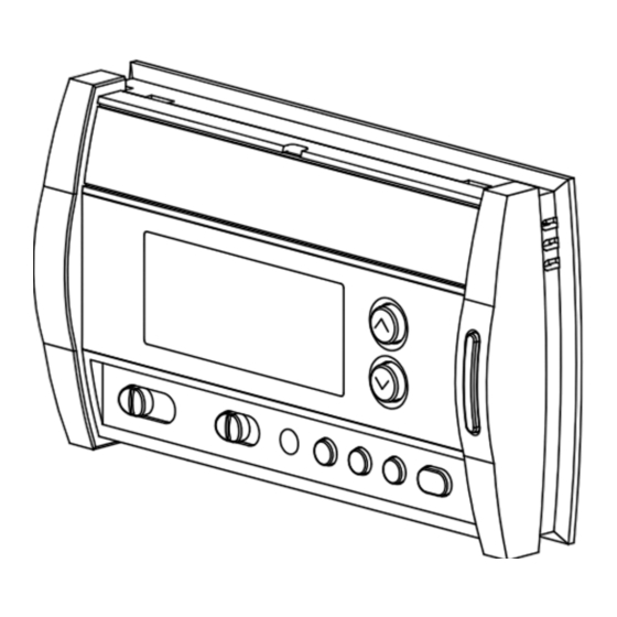
Display
System operating
Fan operating
mode selector
mode selector
Features
• System operating mode selection: heat, cool or off
• Fan operating mode selection: automatic or on (continuous)
• Programmable heating and cooling cycle lengths: 10, 12, 15, 20
or 30 minutes
• Temperature display in °F or °C
• Backlit display
• Battery replacement indicator
• 7-day programming including:
- Preprogrammed energy-saving schedule
- Early Start
- Temporary bypass
- Time display (12 h or 24 h)
• Filter replacement indicator
• Automatic daylight savings changeover
• Interchangeable faceplates (titanium, charcoal & taupe)
2. Installation
2.1 Removing the Old Thermostat
IN ORDER TO AVOID ANY RISK OF ELECTRIC SHOCK, CUT
POWER TO THE HEATING/COOLING SYSTEM.
Remove the old thermostat to access the wires.
Warning: If the old thermostat was mounted onto an electrical box,
it was probably powered by 120/240 volts. In this case, this thermo-
stat cannot be used.
RTH2520
RTH2520
Programmable Thermostat
Installation and User Guide
Adjustment
buttons
Backlight
button
Programming
buttons
Identify and label each wire (with the corresponding letter on
the wire terminal) and remove them from the terminals.
If necessary, strip the end of each wire (maximum of 1/4 inch).
Wrap the wires around a pencil to prevent
them from falling into the wall.
If the hole in the wall is too big, insulate it
using a non-flammable material in order to
avoid air draughts behind the thermostat.
2.2 Installing the New Baseplate
For a new installation, choose a location approximately 5 feet
(1.5 m) above the floor and on an inside wall. Avoid draughty
areas (top of staircase, air outlet, etc.), dead air spots (behind
doors), direct sunlight or areas near concealed pipes or chim-
neys.
Remove the thermostat faceplate.
Loosen the locking screw in order to separate the thermostat
from its baseplate (the screw cannot be completely removed).
Gently tilt the thermostat upwards.
Mark and bore the appropriate mounting holes (using a 3/16"
drill bit) or use the existing holes. Insert the plastic anchors.
Pass the wires through the opening of the baseplate and fix the
baseplate to the wall using the screws provided.
2.3 Connecting the Thermostat
Refer to the following table for matching the wire labels with the
thermostat terminals.
RTH2520 terminals
Rh
Heating power supply
Rc
Cooling power supply
W
Heating signal
Y
Cooling signal
G
Fan
Note: Do not connect wires identified as C, X or B. Wrap the bare
end of these wires with electrical tape.
Important: The red jumper wire between Rh and Rc terminals must
be removed in a 5-wire installation.
Description
Wire labels
Rh, R, 4, V
Rc, R
W, W1, H
Y, Y1, M
G, F
69-1867ES-05
69-1867ES—05
03-11
1/8
Advertisement
Table of Contents

Related Manuals for Honeywell RTH2520B


Summary of Contents for Honeywell RTH2520B
-
Page 1: Installation
RTH2520 Identify and label each wire (with the corresponding letter on the wire terminal) and remove them from the terminals. Programmable Thermostat If necessary, strip the end of each wire (maximum of 1/4 inch). Installation and User Guide Wrap the wires around a pencil to prevent them from falling into the wall. -
Page 2: Wiring Diagrams
2.4 Setting JP2 Jumper 2.3.1 2-wire Heating The jumper specifies how the fan will operate JP2 jumper when it is placed in automatic mode (see sec- tion 3.2). Jumper Leave the jumper in this position if you have a gas or oil heating system. Heat relay Move the jumper to this position if you have an electric heating system. -
Page 3: Configuration Menu
3.2 Fan Operating Mode After replacing the batteries, set the time, day and date (see sec- tions 5.1 and 5.2). However, the temperature and program settings Use the selector switch to set the fan to automatic are saved and do not need to be re-entered. mode (AUTO) or continuous mode (ON). -
Page 4: Technical Specifications
Note: If you wish to use only 2 periods, set periods “1 and 4” or shall not apply if it is shown by Honeywell that the defect or malfunction was caused by damage which occurred while the product was in the possession periods “2 and 3”. -
Page 5: Instalación
RTH2520 Identifique y rotule los cables (con la letra correspondiente en la terminal de cada cable) y quítelos de las terminales. Termostato programable Si es necesario, pele el extremo de cada cable (un máximo de ¼"). Instalación y guía para el usuario ... -
Page 6: Funciones Básicas
2.4 Configuración del puente JP2 2.3.1 Calefacción con 2 cables El puente especifica como funcionará el venti- Puente JP2 lador cuando se lo coloque en modo automático (vea la sección 3.2). Puente Si tiene un sistema de calefacción que funcione con gas o con aceite, deje el calefacción puente en esta posición. -
Page 7: Menú De Configuración
3.8 Indicador de cambio de baterías Nota: Cuando coloque el termostato en el modo de enfriamiento, quizás tenga que esperar cinco minutos antes de que comience a Cuando el icono comience a parpadear, instale baterías enfriar. Esta es una característica de seguridad para el compresor. El nuevas. -
Page 8: Especificaciones Técnicas
Enfriamiento 78°F (25.5°C) Calefacción 62°F (16.5°C) Honeywell garantiza por un período de un (1) año, a partir de la fecha de compra por el 8:00 a.m. consumidor, que este producto, sin incluir las baterías, no presentará defectos en los Enfriamiento 85°F (29.5°C)