Table of Contents
Advertisement
For Pentium
The author assumes no responsibility for any errors or omissions which
may appear in this document nor does it make a commitment to update
the information contained herein.
Trademark:
*
Pentium is registered trademark and MMX is a trademark of Intel corporation,
the other names and brands are the property of their respective owners.
*
Specifications and Information contained in this documentation are furnished for information use only, and are subject to
change at any time without notice, and should not be construed as a commitment by manufacturer.
993AS-L/993AS
/993AN
USER'S MANUAL
PCIAGP Mainboard
II/ III or Socket 370
NO. G03-993ANR3A
Release date: NOV 2000
** Year 2000 compliant **
Advertisement
Table of Contents

Related Manuals for JETWAY 993AN


Summary of Contents for JETWAY 993AN
- Page 1 993AS-L/993AS /993AN USER'S MANUAL PCIAGP Mainboard For Pentium II/ III or Socket 370 The author assumes no responsibility for any errors or omissions which may appear in this document nor does it make a commitment to update the information contained herein.
-
Page 2: Table Of Contents
TABLE OF CONTENT Chapter 1 1-1 Preface......................1 1-2 Feature of motherboard ................... 1 1-2-1 Overview....................1 1-2-2 Key Feature ..................2 Chapter 2 Hardware Installation .................. 3 2-1 Unpacking ......................3 2-2 Mainboard Diagram..................4 2-3 Quick Reference for Jumpers, Connectors & Expansion Socket ....... 5 2-4 Installation Steps.................... -
Page 3: Preface
Chapter 1 1-1 Preface Thank you for purchasing this multifunction motherboard. It has the most flexibility you can find Pentium ® II / Pentium ® III in today’s computer market. The mainboard integrates both Intel & Celeron™(Slot 1 & Socket 370) processor interface into a compact PC/AT compatible system along with 3D Stereo Sound System audio chip. -
Page 4: Key Feature
1-2-2 Key Feature • Multi-Speed Support : Provide 66/75*/83*/95*/100/112*/117*/124*/133*/150*MHz Front Pentium ® II / Pentium ® Side Bus Frequency to support Intel III, Celeron processor for Slot1 interface or Intel Celeron PPGA on a ZIP Socket 370 interface. • Chipset : VIA Apollo Pro AGPset . •... -
Page 5: Hardware Installation
Chapter 2 Hardware Installation 2-1 Unpacking This mainboard package should contain the following: • The mainboard • USER’S MANUAL for mainboard • Cable set for Ultra DMA 66 IDE x1, Floppy x1 • CD for Drivers PACK The mainboard contains sensitive electronic components that can be easily damaged by electron-static, so the mainboard should be left in its original packing until it is installed. -
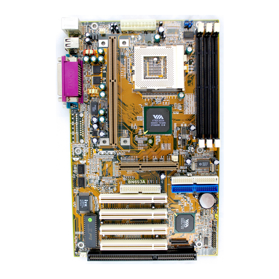
Page 6: Mainboard Diagram
2-2 Mainboard Diagram ATX POWER CONN. CPUFAN DIM M 1 DIM M 2 DIM M 3 SLOT-1 VIA Apollo Pro GAM E JP12 SYSFAN JP11 IDE2 IDE2 AGP1 IDE1 IDE1 S P K IN 1 S P D IF IN 1 B T 1 S P D IF O U T J P 1... -
Page 7: Quick Reference For Jumpers, Connectors & Expansion Socket
2-3 Quick Reference for Jumpers, Connectors & Expansion Socket Jumpers Jumper Name Description Page JP11,JP12 CPU Bus Frequency Selection Refer to page 6 p. 6 CPU Ratio Selector Refer to page 6 p. 6 JP14 CMOS RAM Clear 1-2 Normal ,2-3 Clear CMOS p. -
Page 8: Installation Steps
2-4 Installation Steps Before using your computer, you must follow the steps as follows: 1. Set Jumpers on the Mainboard 2. Install the CPU 3. Install DRAM Modules 4. Install Expansion card 5. Connect Cables, Wires, and Power Supply 2-5 Jumper Settings 1. -
Page 9: System Memory (Dram)
CMOS RAM Clear: JP14 (Yellow color selector) WARNING: Make sure your computer is POWER OFF when you CLEAR CMOS. Connect a jumper Cap over this jumper for a few seconds, will clears information stored in the CMOS RAM Chip that input by user, such as hard disk information and passwords. After CLEAR CMOS, you must enter the BIOS setup (by holding down <DEL>... - Page 10 2-7-2 The mainboard also provides a 370-pin ZIF Socket 370. The CPU on mainboard must have a fan attached to prevent overheating. To install a CPU, first turn off your system and remove its cover. Locate the ZIF Socket and open it by first pulling the lever sideways away from the socket then upwards to a 90-degree right angle.
- Page 11 Reference Design: Heatsink Intel’s reference design thermal solution is an active heatsink; an extruded aluminum heatsink base and a fan attached to the top on the fin array. • Heatsinks for the PPGA will not work with the FC-PGA. A pedestal is required on the underside of the heatsink to clear the socket FC-PGA with the reference cam box...
- Page 12 Heatsink Attachment Step 1 Remove the protective liner from the thermal interface material on the underside of the heatsink. This liner is not normally present on the Intel reference active heatsink. Step 2 Orient the heatsink with the keyed edge of heatsink along the cam box side of the processor.
-
Page 13: Expansion Cards
2-8 Expansion Cards You must read the documentation come with expansion card for any hardware or software settings that may be required to setup your specific card. Installation Procedure: 1. Read the documentation from your expansion card. 2. Set any necessary jumpers on your expansion card. 3. - Page 14 2. PS/2 Mouse & PS/2 Keyboard Connector: MINI-DIN The connectors for PS/2 keyboard and PS/2 Mouse. PS/2 Mouse PS/2 Keyboard 3. USB Port connector: USB The connectors are 4-pins connector that connect USB devices to the system board. USB Port Connector 4.
- Page 15 Pin 1 Floppy drive Connector 7. Primary IDE Connector (40-pin block): IDE1 This connector supports the provided IDE hard disk ribbon cable. After connecting the single plug end to mainboard, connect the two plugs at other end to your hard disk(s). If you install two hard disks, you must configure the second drive to Slave mode by setting its jumpers accordingly.
- Page 16 SMI Switch 11. Turbo LED switch: TBLED The mainboard‘s turbo function is always on. The turbo LED will remain constantly lit while the system power is on. You may wish to connect the Power LED from the system case to this lead.
- Page 17 16. FAN connector: CPUFAN , SYSFAN CPUFAN SYSFAN FAN Connector 17. Power-On button connector: PS-ON Push Button Power-On button connector 18. Wake On Lan connector: WOL + 5VSB G ND W O N ※ Wake On LAN Function worked only when power supply support 5VSB more than 750mA current.
- Page 18 21. CD Audio in connector : JP2,JP3 JP2 and JP3 are the connectors for CD-Audio Input signal, Please connect it to CD-ROM CD-Audio output connector JP2 :CD-Adio/Panasonic JP3 :CD-Audio/Sony 22. Audio and Game Connector : AGC This Connector are 3 phone Jack for LINE-OUT,LINE-IN,MIC and a 15-pin D-Subminiature Receptacle Connector for joystick/MIDI Device.
- Page 19 24. SPDIF (Sony / Philips Digital Interface) Input / Output Connectors: SPDIFIN 1 / SPDIFOUT SPDIFOUT SPDIFIN SPDIFOUT SPDIFIN 1 25. Optical kit connector: JP7 This connector is for user that has Optical kit(optional) to provide other set of SPDIF INPUT and SPDIF OUTPUT function.
-
Page 20: Chapter 3 Award Bios Setup
Chapter 3 AWARD BIOS SETUP This mainboard has previously set to its best stable status. If you are not an experienced user, please do not change the default setting. When you are encounter any problem, please choice “LOAD STANDARD DEFAULTS” to restore best setting. Award’s ROM BIOS provides a built-in Setup program which allows user modify the basic system configuration and hardware parameters. -
Page 21: Standard Cmos Setup
3-1 STANDARD CMOS SETUP STANDARD CMOS SETUP (Figure 3-2) allows user to configure system setting such as current date and time, type of hard disk drive installed in the system, floppy drive type, and the type of display monitor. Memory size is auto-detected by the BIOS and displayed for your reference. When a field is highlighted (direction keys to move cursor and <Enter>... -
Page 22: Bios Features Setup
BIOS FEATURES SETUP Select the “BIOS FEATURES SETUP” option in the CMOS SETUP UTILITY menu allows user to change system related parameters in the displayed menu. This menu shows all of the manufacturer’s default values of this mainboard. Again, user can move the cursor by pressing direction keys and <PgDn>... -
Page 23: Chipset Features Setup
3-3 CHIPSET FEATURES SETUP This section describes features of the VIA Apollo Pro AGPset. If your system contains a different chipset, this section will bear little resemblance to what you see on your screen. ADVANCED OPTIONS. The parameters in this screen are for system designers, service personnel, and technically competent users only. -
Page 24: Power Management Setup
The Power Management Setup allows you to configure you system to most effectively save energy while operating in a manner consistent with your own style of computer use. ROM PCI/ISA BIOS (2A6LGJ1F) POWER MANAGEMENT SETUP AWARD SOFTWARE, INC. ACPI function : Enabled Primary INTR : ON... - Page 25 Monitor will remain on during power saving modes. Suspend Monitor blanked when the systems enters the Suspend mode. Standby Monitor blanked when the system enters Standby mode. Doze Monitor blanked when the system enters any power saving mode. • MODEM Use IRQ: Name the interrupt request (IRQ) line assigned to the modem (if any) on your system.
-
Page 26: Pnp/Pci Configuration Setup
3-5 PnP/PCI CONFIGURATION SETUP This section describes configuring the PCI bus system. PCI, or Personal Computer Interconnect, is a system which allows I/O devices to operate at speeds nearing the speed the CPU itself uses when communicating with its own special components. This section covers some very technical items and it is strongly recommended that only experienced users should make any changes to the default settings. -
Page 27: Load Standard Defaults
3-7 LOAD STANDARD DEFAULTS The “LOAD STANDARD DEFAULTS” function loads the system Standard default data directly from ROM and initialize associated hardware properly. This function will be necessary only when the system CMOS data is corrupted. ROM PCI/ISA BIOS (2A6LGJ1F) CMOS SETUP UTILITY AWARD SOFTWARE, INC. -
Page 28: Supervisor/User Password
3-9 SUPERVISOR/USER PASSWORD This item lets you configure the system so that a password is required each time the system boots or an attempt is made to enter the Setup program (Refer to Figure 3-3 for the details). Supervisor Password allows you to change all CMOS settings but the User Password setting doesn’t have this function. -
Page 29: Software Installation
Chapter 4 4-1 Mainboard Driver Install in Win9X,WinNT To install the mainboard driver please run X:\VIA\Driver\SETUP.EXE. After execute Setup .EXE the screen will depend on the OS (Operating System) to show the necessary Driver which you have to install in your system, such like IDE Driver, AGP VXD Driver, VIA chipset Feature Registry and IRQ Routing Miniport Driver . -
Page 30: Pc Health Monitor-Iii ( Option For Motherboard That Embedded Pc Health Chip )
PC HEALTH MONITOR-III (OPTION FOR MOTHERBOARD THAT EMBEDDED PC Health) Software for Windows 95/98 Please Run X:\VIA\HEALTH3\SETUP.EXE NOTES 1. For Windows 95 user:You must run SETUP.EXE twice in order to complete this installation. The computer will install device identification at first time when you run SETUP.EXE. When you finish, you need re-start your computer manually and run SETUP.EXE once again to install correspond driver. - Page 31 -12V Low Limit/High Limit These values are used to specify the threshold values of detecting the abnormal condition of , 3.3V, +5V, +12V, -12V. 2. FAN Speed CPUFAN/ SYSFAN If the fan RPM is lower than this value and “CPUFAN/SYSFAN” is enabled in Monitoring Config.
-
Page 32: Sound Driver (Option For Motherboard That Embedded Audio Chip)
Special Features for CMI8738 audio chip PCI Plug and Play (PnP) bus interface, 32 bit PCI bus master. Full duplex playback and recording, built-in 16 bits CODEC. HRTF 3D positional audio, supports both Direct Sound 3D ® & A3D® interfaces, supports earphones, two and four channel speakers mode. - Page 33 7. Now, system is installing device drivers automatically. After a while, the system will finish the installation includes the following device drivers. CMI8738/C3DX PCI Audio Device CMI8738/C3DX PCI Audio Joystick Device CMI8738/C3DX PCI Audio Legacy Device DOS mode MPU-401 Emulator 8.
- Page 34 “X:\CMI8738\NT40\APP\SETUP.EXE” 14. Click “OK” to start the installation procedure, and follow the on-screen instructions to finish the installation. When all of application softwares have been installed, shut down the Windows NT system, and then reboot your system. Windows Appc. (The Audio Rack) Introduction By means of a user-friendly interface(as easy as operating your home stereo system), this PCI audio rack provides you with the control over your PC’s audio functions, including the advantage...
- Page 35 Current Time field: displays the current time of files or tracks in minutes and seconds when playback or recording. Please refer to the help screen for more detail button function descriptions. (click on help “ ” button on the player) System Mixer System Mixer allows you to control all the audio output and input levels.
- Page 36 Mute Buttons: Toggle between muting and enabling the signal. A button with a lit LED is enabled, and when it is not lit, it means it is mute. Several output signals can usually be enabled at once. MP3 Player : MP3 player can play both wave files and MP3 files. MP3 player while the loop function enables.
- Page 37 audio result. 3. The mixer setup There is a 4 speakers option in the volume control of the mixer, and when you enable this option, it means the rear speakers are connected to Line-in/Rear jack. When Line-in/Rear jack is connected to other external Line-in sources, please DO NOT enable this option in order to avoid hardware conflicts.
- Page 38 The application program setup(please install CMI8738 application program first) When the connection is done, please go to the Start menu and select PCI Audio Applications\Audio Environment Setting...
- Page 39 When all the procedures have been completed, there will be an infrared signal coming from the SPDIF/OUT of the optical fiber of the sound card. Please note that signal beam may cause severe damage to the eyes. For your safety, please point the output end to a piece of white paper to check if thebeam is in function.
- Page 40 Please note that in playback, if there is no gap longer than three seconds between each track, the MD can not recognize the tracks and will record all of them into one. It is recommended that you set the gap time to 3~5 seconds to meet all type of MD requirements.
- Page 41 About Recording 24bit Audio Setting...
- Page 42 24-bit audio can only be applied to SPDIF IN/OUT mode; it does not apply to other modes such as the four channels or the analog. No sound will be heard while in playback, yet it can be recorded. The un-selected area will be gray out. The un-selected area will be gray out.
- Page 43 The un-selected area will be gray out. You can double-click this circuit icon to have the following setting box. By means of this setting box, you can also complete the above-mentioned setting procedures.
- Page 44 SPDIF/IN for motherboard that embedded Audio chip An example of Portable CD Player(Output) to Main Board (Optical Input)Setup When the connection is done, please go to the Start menu and select PCI Audio Applications\Audio Environment Setting...
- Page 45 Loopback(bypass)mode setup CD ROM(Digital Output) to SPDIF/IN Setup...
- Page 46 When the connection is done, please go to the Start menu and select PCI Audio Applications\Audio Environment Setting...
- Page 47 Please follow these setting procedures. Now you can insert the CD into the CD ROM drive, then activate C-MEDIA CD player and push the ”play” button to do the recording job. Please note that you have to set the MD in the simultaneous-recording mode.