
Related Manuals for Honeywell EQUIP HCD554IP


Summary of Contents for Honeywell EQUIP HCD554IP
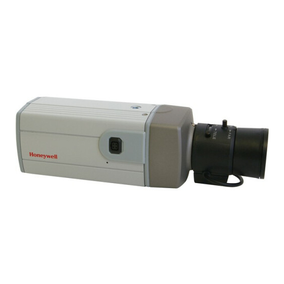
- Page 1 EQUIP™ Series IP Camera NTSC / PAL HCD554IP HCD554IPX HCS554IP HCS554IPX Reference Guide Document 800-00250 – Rev C – 08/08...
- Page 2 Revisions Issue Date Revisions 08/07 New document (Pre-release version). 02/08 Production released version of the manual. 08/08 Revised production released version for technical review comments; Add trademark to EQUIP; updated back cover.
-
Page 3: Table Of Contents
Preparing the Honeywell IP Utility ........ - Page 4 Logging On ..........33 Installing Honeywell IP (ActiveX Plug-in) ......34 Logging Off .
- Page 5 Logon Screen ......... 34 Figure 4-4 Honeywell IP Installation (ActiveX Plug-in) ......35 Figure 4-5 Web-Client: Administrator User .
- Page 6 Figures...
-
Page 7: About This Document
EQUIP Series IP Camera Reference Guide About This Document This document introduces the Honeywell Color Day/Night Network Camera. It covers how to install, configure and operate the camera in a network environment. See Table 0-1 a list of camera models. -
Page 8: Cautions And Warnings
Cautions and Warnings THIS SYMBOL INDICATES CAUTION THAT DANGEROUS VOLTAGE RISK OF CONSTITUTING A RISK OF ELECTRIC SHOCK ELECTRIC SHOCK IS PRESENT DO NOT OPEN WITHIN THE UNIT. CAUTION: TO REDUCE THE RISK OF THIS SYMBOL INDICATES ELECTRIC SHOCK, DO NOT REMOVE THAT IMPORTANT OPERATING THE COVER. -
Page 9: Manufacturer's Declaration Of Conformance
Warranty and Service Subject to the terms and conditions listed on the Product warranty, during the warranty period Honeywell will repair or replace, at its sole option, free of charge, any defective products returned prepaid. In the event you have a problem with any Honeywell product, please call Customer Service at 1.800.796.CCTV for assistance or to request a Return Merchandise... -
Page 11: Introduction
Introduction The Honeywell color day/night network camera provides high picture quality remote video surveillance over a network connection. See Table 1-1 for a list of camera models. Table 1-1 Network Camera Model Numbers Model Number Description HCD554IP True Day/Night Network Camera, NTSC, Analog output... -
Page 12: Features
Excellent signal-to-noise ratio of more than 50 dB • Supports Filter moving Day/Night (HCD554IP) and Electronic Day/Night (HCS554IP) function • Minimum illumination of 0.7 lux color, 0.2 lux B/W (HCD554IP) or 0.5 lux B/W (HCS554IP) • Compatible with Manual Iris lens or DC Iris lens •... -
Page 13: Installation And Setup
Before you Begin Please read this guide carefully before you install the network camera. Keep this guide for future reference. Before installing the camera, Honeywell recommends that you check www.honeywellvideo.com/products/cameras/ to find your camera and download the latest manuals and software updates. -
Page 14: Overview Of Installation Procedure
Camera Components and Functions The network camera is intended for indoor use only. If you choose to mount the camera outdoors, you must employ a suitable weatherproof enclosure (such as Honeywell’s HHC12 camera housing) with your network camera. See www.honeywellvideo.com information on Honeywell weatherproof enclosures and mounting brackets. -
Page 15: Adjusting The Back Focus
Some installation codes state that the mounting bracket must be capable of supporting up to four times the combined weight of the camera and lens. For outdoor applications, mount the camera inside a weatherproof enclosure. See www.honeywellvideo.com for information on Honeywell weatherproof enclosures. Document 800-00250 Rev C 08/08... -
Page 16: Wiring
Installation and Setup Figure 2-2 Camera Mount Use standard size mounting bolts (1/4 x 20) to mount the camera on a bracket or tripod. Wiring Figure 2-3 Camera Connections Connect to spot monitor V ID E O 24 VAC/12 VDC O U T O U T power... -
Page 17: Connecting Power
EQUIP Series IP Camera Reference Guide Network RJ-45 Ethernet Connection The main video connection for your network camera will be made through your Ethernet network connection. Connect the Ethernet connector on the rear of the camera to your network using an Ethernet (10Base-T, 100Base-TX) cable. Note You can connect your camera to a network or connect it directly to a PC or laptop using a crossover cable. -
Page 18: Connecting Alarms
Installation and Setup Note To ease installation, the terminal block can be removed. The power connections of the removable terminal block are not polarity-sensitive. Connect either power lead to either connector terminal. Secure the power leads by retightening the terminal screws until snug. Plug the power supply into an appropriate power source. -
Page 19: Figure 2-4 Alarm Connections
EQUIP Series IP Camera Reference Guide Figure 2-4 Alarm Connections ALARM Connect mechanical or electrical switches to the alarm input connection to allow event-triggered recording. When alarm inputs are configured, the camera triggers an alarm only when the normal state (open or closed) changes (see Figure 2-5). -
Page 20: Connecting Audio
Installation and Setup The alarm output can be configured to provide normally open or normally closed contacts (see Device Settings on page to configure the alarm output). Contacts will be rated for 12 VDC @ 0.5 A. Connecting Audio The network camera supports bi-directional audio. There are two supported voice band channels that function in full duplex mode. -
Page 21: Configuring Network Settings
Ethernet cable (see Network RJ-45 Ethernet Connection on page 17). System Requirements The Honeywell IP Utility should be installed on a work station that meets the following minimum requirements: Table 3-1 PC Minimum System Requirements Component Requirement ®... -
Page 22: Installing The Ip Utility
Honeywell IP Utility is being installed. To Install the IP Utility Insert the CD into your CD-ROM drive and the Honeywell IP Utility InstallShield wizard appears. If InstallShield does not begin automatically, use Windows Explorer to navigate to the CD drive and double-click Honeywell IP Utility Setup.exe. -
Page 23: User Profiles
EQUIP Series IP Camera Reference Guide Open Add or Remove Programs and then select Honeywell IP Utility in the Currently installed programs list. Click Change. The IP Utility Installation Wizard screen appears. Click Next, and then click Remove. The Honeywell IP Utility is removed. -
Page 24: Changing The User Password
Figure 3-1 IP Utility Login Screen From the Username list, select Administrator or Guest. Type the case-sensitive Password and click . The Honeywell IP Utility appears. Note The default Administrator password is 1234 and the default Guest password is guest. -
Page 25: User Interface
Apply, all your new settings will be lost. User Interface The user interface of the Honeywell IP Utility provides access to network configuration and user settings through the Title bar, Discovery pane, Tabs and Status bar (see Figure 3-3). -
Page 26: Ip Camera Network Configuration
Configuring Network Settings IP Camera Network Configuration Discovering Devices When you log on to the IP Utility, the devices on the network—including the devices on other subnets—are automatically discovered and listed in the Discovery pane. After the initial discovery, auto-refresh continues to discover devices that are newly added or removed from the network. -
Page 27: Configuring Ip Network Settings
EQUIP Series IP Camera Reference Guide Configuring IP Network Settings The IP network setting details such as device name, IP address, and subnet mask can be configured for each connected device. Updating IP Network Settings Automatically To update the IP network settings of a device automatically: In the Discovery pane, select the device and click On the System tab, select Obtain an IP Address automatically. -
Page 28: Figure 3-5 Ip Network Settings Obtained Manually
Configuring Network Settings Under IP Network Setting, enter the following details: Table 3-3 IP Network Setting Options of the Device Option Description Obtain an IP Address This option must NOT be checked to assign a static IP automatically address to the device. Device Name The name of the device MAC Address... -
Page 29: Upgrading The Firmware
EQUIP Series IP Camera Reference Guide Upgrading the Firmware To Upgrade the Firmware of the Network Camera Check www.honeywellvideo.com/support/downloads/downloads_cam.html and find your camera in the list. Click the firmware link to download the file. In the Discovery pane, select the device to upgrade and click Figure 3-6 IP Utility Firmware Upgrade Click Upgrade Firmware. -
Page 30: Changing Web-Client Application Password
Configuring Network Settings Changing Web-Client Application Password The IP Utility enables you to change the password for the network camera Web-Client. To Change the Password of the Web-Client Application Select the device from the Discovery pane and click Click the Users tab. Figure 3-7 Changing Web-Client User Passwords Select the Username. -
Page 31: Ip Camera Web-Client
IP Camera Web-Client Overview The network camera Web-Client is a web-based application that enables you to view video, listen to audio, and configure camera and sabotage detection settings for the network camera. Note Certain features of the IP Camera Web-Client are user-based and are available only to the administrator. -
Page 32: Accessing The Ip Camera Web-Client
IP Camera Web-Client Accessing the IP Camera Web-Client First Time Setup Requirements Live images can be viewed from an internet browser with the Web-Client interface. An ActiveX® control must be downloaded to your computer before you will be able to view video. -
Page 33: Logging On
EQUIP Series IP Camera Reference Guide Figure 4-2 Security Settings Click OK on the Security Settings dialog box. Select Local Intranet and click the Custom Levels security button. Scroll down the list to the ActiveX controls and plug-ins options and enable all ActiveX control functions on the list (see step Click OK on the Security Settings dialog box. -
Page 34: Installing Honeywell Ip (Activex Plug-In)
The Web-Client appears. Installing Honeywell IP (ActiveX Plug-in) If this is the first time you’ve logged on, you may have to install the Honeywell IP ActiveX control. If the InstallShield Wizard opens (Figure 4-4), click Next and follow the rest of the InstallShield Wizard instructions to complete the installation. -
Page 35: Logging Off
Uninstalling Honeywell IP (ActiveX Plug-in) Click Start, and then choose Control Panel. The Control Panel window appears. Double-click Add or Remove Programs and then select Honeywell IP from the Currently installed programs list. Click Change/Remove to remove the component. -
Page 36: Navigating The User Interface
IP Camera Web-Client Navigating the User Interface The user interface of the Web-Client application consists of multiple user-friendly views organized by functionality. Access to the views is user controlled. Table 4-2 Tabs/Views in the Web-Client Application Enables you to... Live View View video. -
Page 37: Live View
4-6). Device Settings The Device Settings view mirrors the information that is available in the Honeywell IP Utility. It provides network and firmware settings without having to access the IP Utility. The device Alarm Settings are also configurable in this view. Set the Alarm Input as Normally Open, Normally Close, LAMP (HCD554IP/X only) or Disable. -
Page 38: Figure 4-7 Device Settings
IP Camera Web-Client closed) changes. The LAMP setting allows control of the moving IR cut filter and day/night operation to be synchronized with a common controller. See Connecting Alarms on page for more information. Connect external devices such as sirens or flashing lights to the alarm output connector to signal users of the camera that an alarm is activated. -
Page 39: Compression Settings
EQUIP Series IP Camera Reference Guide Compression Settings The video signal sent to the Web-Client from the camera has a number of settings that can be edited which effect the video as it’s displayed in the Web-Client. The Compression Settings view enables you to configure settings such as Resolution, Frame Rate and Picture Quality. -
Page 40: Compression Settings
IP Camera Web-Client Compression Settings The quality of the video displayed can be configured as needed using the Compression Settings. Use the following table to set up video compression. Table 4-3 Compression Settings Setting Options Description Resolution 4CIF, 2CIF, CIF 4CIF is the highest resolution and CIF is the lowest resolution. -
Page 41: Auto Exposure
EQUIP Series IP Camera Reference Guide Note You must click Apply for your changes to take effect. If you close the screen before clicking Apply, all your new settings will be lost. Figure 4-9 Camera Setup Auto Exposure The camera lens, lighting and true day/night options can be configured as needed using the Auto Exposure settings. -
Page 42: White Balance
Day/Night Auto, Manual On, Set the moving, mechanical IR filter within the camera to ensure true Manual Off 24 hour surveillance (HCD554IP/X only). Detect Time 5–60 seconds Sets the time (5–60 seconds) before the camera switches to Day or Night mode after detecting a low light condition. -
Page 43: Video Analytics
EQUIP Series IP Camera Reference Guide Note You must click Apply for your changes to take effect. If you close the screen before clicking Apply, all your new settings will be lost. Table 4-5 White Balance Settings Option Description ATW (Auto Trace White Feedback system that automatically aligns the white Balance Mode) balance (2800°K to 8000°K). -
Page 44: Video Blurring
IP Camera Web-Client Figure 4-10 Video Analytics Each Tamper Detection Setting provides 3 threshold levels: High (80%), Medium (50%) and Low (30%). Figure 4-11 Video Analytics Message Video Blurring The video appears blurred when the camera is exposed to elements such as water. When this occurs, video blurring in the field of view is detected and shows an alarm message (see Figure 4-11) above the video display. -
Page 45: Camera Blinding
EQUIP Series IP Camera Reference Guide In the Blur Threshold list, select one of the following options: Table 4-6 Blur Threshold Values Value To detect ... High (80%) Maximum video blurring. The alarm message appears when the video display is blurred by 80% and above. Medium (50%) Medium video blurring. -
Page 46: Camera Field Of View Change
IP Camera Web-Client Note To turn off camera blind detection, select Disable in the Blinding Threshold list. Disable is the default value. Note You must click Apply for your changes to take effect. If you close the screen before clicking Apply, all your new settings will be lost. Camera Field of View Change The Web-Client application can detect tampering of the camera field of view and show an alarm message above the video display (see... -
Page 47: Appendix A Troubleshooting
Troubleshooting Technical Support Prior to calling Honeywell technical support, refer to the following topics for possible solutions to problems with your network camera. To contact the Honeywell Video Systems technical support team, call 1-800-796-2288 (North America only) or send an e-mail to HVSsupport@honeywell.com. -
Page 48: Problem: Cannot Connect To A Device
If your internet security settings are set to “Prompt” you to install ActiveX controls, you may see a warning similar to Figure A-2. Click Install to install the ActiveX control. See Installing Honeywell IP (ActiveX Plug-in) on page for the installation procedure. Figure A-2... -
Page 49: Appendix B Specifications
Specifications Note These specifications refer to all models, except where otherwise noted. Specifications are subject to change without notice. Table B-1 Camera Specifications Specification HCD554IP HCS554IP Operational Image Sensor 1/3” CCD Lens Mount CS Lens Mount Video Standard NTSC or PAL... - Page 50 Specifications Table B-1 Camera Specifications (cont’d) Specification HCD554IP HCS554IP IP Specifications Video Compression MPEG-4 Part 2 (ISO/IEC 14496-2) SP level 0–3 Resolutions 4CIF, 2CIF, CIF, 704x480 (NTSC), 704x576 (PAL) Frame Rate (NTSC/PAL) Up to 30/25 fps video in all resolutions Video Streaming MPEG-4 controllable frame rate and bandwidth.
-
Page 51: Figure B-1 Network Camera Dimensions
EQUIP Series IP Camera Reference Guide Figure B-1 Network Camera Dimensions V ID E O E TH E R N E T A U D I O O U T Document 800-00250 Rev C 08/08... - Page 52 Specifications...
- Page 54 Document 800-00250 – Rev C – 08/08 © 2008 Honeywell International Inc. All rights reserved. No part of this publication may be reproduced by any means without written permission from Honeywell Video Systems. The information in this publication is believed to be accurate in all respects. However, Honeywell Video Systems cannot assume responsibility for any consequences resulting from the use thereof.