Cisco CISCO871-K9 - 871 Integrated Services Router Hardware Installation Manual
Access routers
Hide thumbs
Also See for CISCO871-K9 - 871 Integrated Services Router:
- Configuration manual (196 pages)
Table of Contents
Advertisement
Advertisement
Chapters
Table of Contents
Troubleshooting

Related Manuals for Cisco CISCO871-K9 - 871 Integrated Services Router


Summary of Contents for Cisco CISCO871-K9 - 871 Integrated Services Router
- Page 1 Cisco 850 Series and Cisco 870 Series Access Routers Hardware Installation Guide Corporate Headquarters Cisco Systems, Inc. 170 West Tasman Drive San Jose, CA 95134-1706 http://www.cisco.com Tel: 408 526-4000 800 553-NETS (6387) Fax: 408 526-4100 Text Part Number: OL-5331-01...
- Page 2 You can determine whether your equipment is causing interference by turning it off. If the interference stops, it was probably caused by the Cisco equipment or one of its peripheral devices. If the equipment causes interference to radio or television reception, try to correct the interference by using one or more of the following measures: •...
-
Page 3: Table Of Contents
Router Memory 1-16 Router Hardware Security 1-17 Regulatory Compliance 1-17 Preinstallation Information C H A P T E R Safety Warnings and Guidelines Additional Warnings for Wireless Routers Cisco 850 Series and Cisco 870 Series Access Routers Hardware Installation Guide OL-5331-01... - Page 4 Connecting the AC Adapter 4-21 Verifying Router Operations 4-24 What to Do Next 4-25 Initial Configuration C H A P T E R Installing Cisco Router and Security Device Manager Cisco 850 Series and Cisco 870 Series Access Routers Hardware Installation Guide OL-5331-01...
- Page 5 Power-over-Ethernet Module Specifications LAN Port Pinouts Console Connector Pinouts ADSL Port Connector Pinouts Power Output Connector Pinouts Cable Specifications Ethernet Cable Specifications Maximum Cable Length N D E X Cisco 850 Series and Cisco 870 Series Access Routers Hardware Installation Guide OL-5331-01...
- Page 6 Contents Cisco 850 Series and Cisco 870 Series Access Routers Hardware Installation Guide OL-5331-01...
-
Page 7: Preface
Some information may not apply to your particular router model. For warranty, service, and support information, see the “Cisco One-Year Limited Hardware Warranty Terms” section in the Cisco 850 Series and Cisco 870 Series Access Routers Cabling and Setup Quick Start Guide that was shipped with your router. -
Page 8: Organization
Note material. This symbol means reader be careful. In this situation, you might do something that could result in Caution equipment damage or loss of data. Cisco 850 Series and Cisco 870 Series Access Access Routers Hardware Installation Guide OL-5331-01... - Page 9 üblichen Verfahren zur Vorbeugung vor Unfällen vertraut. Suchen Sie mit der am Ende jeder Warnung angegebenen Anweisungsnummer nach der jeweiligen Übersetzung in den übersetzten Sicherheitshinweisen, die zusammen mit diesem Gerät ausgeliefert wurden. BEWAHREN SIE DIESE HINWEISE GUT AUF. Cisco 850 Series and Cisco 870 Series Access Access Routers Hardware Installation Guide OL-5331-01...
- Page 10 Använd det nummer som finns i slutet av varje varning för att hitta dess översättning i de översatta säkerhetsvarningar som medföljer denna anordning. SPARA DESSA ANVISNINGAR Cisco 850 Series and Cisco 870 Series Access Access Routers Hardware Installation Guide OL-5331-01...
- Page 11 Preface Conventions Cisco 850 Series and Cisco 870 Series Access Access Routers Hardware Installation Guide OL-5331-01...
- Page 12 Brug erklæringsnummeret efter hver advarsel for at finde oversættelsen i de oversatte advarsler, der fulgte med denne enhed. GEM DISSE ANVISNINGER Cisco 850 Series and Cisco 870 Series Access Access Routers Hardware Installation Guide OL-5331-01...
- Page 13 Preface Conventions Cisco 850 Series and Cisco 870 Series Access Access Routers Hardware Installation Guide OL-5331-01...
-
Page 14: Related Documentation
Related Documentation Related Documentation In addition to the Cisco 850 Series and Cisco 870 Series Routers Hardware Installation Guide (this document), the Cisco 850 series and Cisco 870 series routers document set includes the following: Cisco 850 Series and Cisco 870 Series Access Routers Cabling and Setup Quick Start Guide •... -
Page 15: Chapter 1 Product Overview
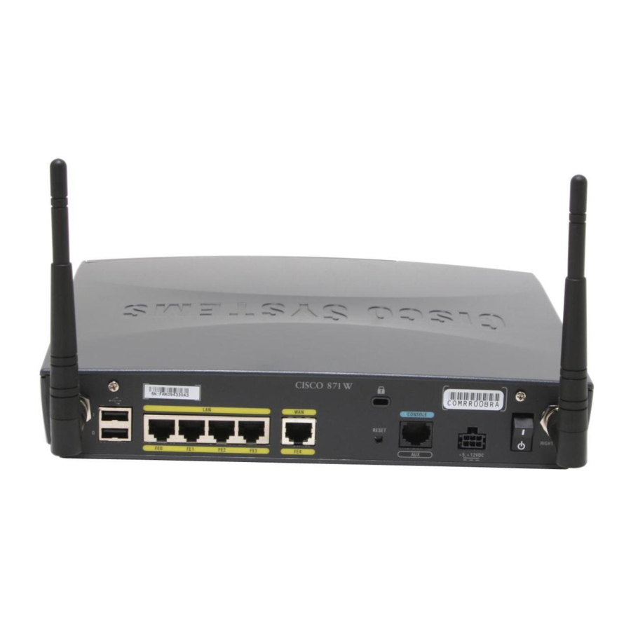
Internet service provider (ISP) over a broadband or Ethernet connection to a corporate LAN or to the Internet. The Cisco 851 and Cisco 871 routers are switch-capable routers that provide a 4-port Ethernet switch for the LAN. These routers are capable of bridging and multiprotocol routing between LAN and WAN ports. - Page 16 SN: XXXNNNNXXXX CONSOLE RESET +5,+12 VDC Figure 1-3 Cisco 871 Router Back Panel with Antennas Cisco 871W SN: XXXNNNNXXXX CONSOLE RESET LEFT RIGHT / PRIMARY +5,+12 VDC Cisco 850 Series and Cisco 870 Series Access Routers Hardware Installation Guide OL-5331-01...
-
Page 17: Router Ports On The Cisco 851 And Cisco 871 Back Panel
General Descriptions of the Router Models Router Ports on the Cisco 851 and Cisco 871 Back Panel The Cisco 851 and Cisco 871 routers have the following ports on the back panel: Four 10/100BASE-T RJ-45 Fast Ethernet LAN ports with a built-in switch •... - Page 18 SN: XXXNNNNXXXX ADSLoPOTS CONSOLE RESET +5,+12 VDC Figure 1-6 Cisco 877 Router Back Panel, with Antennas Installed Cisco 877W SN: XXXNNNNXXXX ADSLoPOTS CONSOLE RESET LEFT RIGHT/PRIMARY +5,+12 VDC Cisco 850 Series and Cisco 870 Series Access Routers Hardware Installation Guide OL-5331-01...
-
Page 19: Router Ports On The Cisco 857 And Cisco 877 Back Panel
General Descriptions of the Router Models Router Ports on the Cisco 857 and Cisco 877 Back Panel The Cisco 857 and Cisco 877 routers have the following ports on the back panel: Four 10/100BASE-T RJ-45 Fast Ethernet LAN ports with a built-in switch •... -
Page 20: Router Ports On The Cisco 876 Back Panel
One RJ-45 console port Cisco 878 SHDSL Router The Cisco 878 router can connect a corporate telecommuter or small office to an Internet service provider (ISP) over multirate symmetrical high-data-rate digital subscriber lines (G.SHDSLs) to a corporate LAN and to the Internet. -
Page 21: Router Ports On The Cisco 878 Back Panel
Cisco 851 and Cisco 871 routers only. Provides connection to 10/100BASE-T. Can be connected to other network devices, such as cable modem, ADSL, and router. ADSL-over-POTS port Cisco 857 and Cisco 877 routers only. Provides connection to an ADSL network. Does not support the autoswitch function. ISDN S/T port Cisco 876 and Cisco 878 routers only. - Page 22 Cisco 870 series routers: 20 MB of flash memory (default) 28 MB of flash memory for routers ordered with a Cisco IOS Advanced IP Services image or Enterprise Services image. Expandable by 8, 16, or 32 MB, up to a maximum of 52 MB.
-
Page 23: Hardware Features
Chapter 1 Product Overview Hardware Features Hardware Features This section provides an overview of the hardware features of Cisco 850 series and Cisco 870 series routers and includes the following topics: Serial Number Location • LED Indicators on the Routers •... - Page 24 Cisco 851, no data is being uploaded. Cisco 871 ADSL CD Green On if the ADSL carrier detects status and connects to the DSLAM. Cisco 857, Cisco 876, Cisco 877 ADSL RXD Green Blinks when the ADSL interface receives data. Off when there is no Cisco 857, data.
-
Page 25: Integrated 802.11B/G Radio Module (Wireless Models Only)
Integrated 802.11b/g Radio Module (Wireless Models Only) The Cisco 850 series and Cisco 870 series wireless routers have an integrated IEEE 802.11b/g radio module that operates as a wireless access point in infrastructure mode. The wireless routers have two reverse-polarity threaded Neill-Concelman (RP-TNC) connectors on the back panel. -
Page 26: Supported Cisco Radio Antennas (Wireless Models Only)
Hardware Features Supported Cisco Radio Antennas (Wireless Models Only) Table 1-3 lists the Cisco antennas that are supported on the Cisco 850 series and Cisco 870 series wireless routers. Table 1-3 Cisco Antennas Supported on the Cisco 850 Series and Cisco 870 Series Wireless Routers... - Page 27 Figure 1-13 Power-over-Ethernet Module Back Panel TO LAN LED indicators and Ethernet ports for Power indicator connecting powered devices Cisco 850 Series and Cisco 870 Series Access Routers Hardware Installation Guide 1-13 OL-5331-01...
- Page 28 Cisco 870 series router Router power adapter Ethernet cables on the PoE module (four PoE power plug RJ-45 connectors in series) PoE module Router power plug PoE power adapter Cisco 850 Series and Cisco 870 Series Access Routers Hardware Installation Guide 1-14 OL-5331-01...
- Page 29 Four RJ-45 Ethernet plugs, in series, from the PoE module (plug these into the Ethernet ports on the router) RJ-45 Ethernet ports on the router PoE module Cisco 850 Series and Cisco 870 Series Access Routers Hardware Installation Guide 1-15 OL-5331-01...
-
Page 30: Led Indicators On The Poe Module
• Flash Memory Flash memory stores the image of the ROMMON boot code, the Cisco IOS software, and the router configuration file. The router provides two onboard StrataFlash devices, one with 16 MB and the other with 4 MB of memory, for a total of 20 MB of onboard flash memory. -
Page 31: Router Hardware Security
• For Cisco 870 series routers, an expansion slot allows for an additional 8 MB, 16 MB, or 32 MB of memory. The maximum flash memory is 52 MB. The default flash memory depends on which Cisco IOS image is ordered with the router. - Page 32 Chapter 1 Product Overview Regulatory Compliance Cisco 850 Series and Cisco 870 Series Access Routers Hardware Installation Guide 1-18 OL-5331-01...
-
Page 33: Chapter 2 Preinstallation Information
Preinstallation Information This chapter provides information about safety, unpacking the router, and preparing for installation for Cisco 851, Cisco 857, Cisco 871, Cisco 876, Cisco 877, and Cisco 878 routers. It contains the following sections: Safety Warnings and Guidelines, page 2-1 •... - Page 34 Alternative arrangements should be made for access to emergency services. Access to emergency services can be affected by any call-barring function of this equipment. Statement 199 Inline power circuits provide current through the communication cable. Use the cable provided by Cisco Caution or a communication cable with a minimum of 24 AWG.
-
Page 35: Additional Warnings For Wireless Routers
This device is intended for use in residential and commercial environments only. Periodically check the resistance value of the antistatic strap, which should be between 1 and Caution 10 megohms (Mohm). Cisco 850 Series and Cisco 870 Series Access Routers Hardware Installation Guide OL-5331-01... -
Page 36: Preventing Damage To The Router
6. Power cords are ordered as applicable to country or geographic region. 7. Includes the Regulatory Compliance and Safety Information for Cisco 800 Series and SOHO Series Routers document and the Cisco 850 Series and Cisco 870 Series Access Routers Cabling and Setup Quick Start Guide. Also includes the Declarations of Conformity and Regulatory Information for Cisco Access Products with 802.11a/b/g and 802.11b/g Radios document for wireless models. -
Page 37: Preparing For Installation
Gather the Ethernet devices to be connected to the router: hub, servers, and workstations or PCs. Make sure that there is a network interface card (NIC) in each device for connection to Ethernet ports. If you plan to configure the software using Cisco IOS commands using the console port, provide an Step 6 ASCII terminal or a PC that is running terminal emulation software to connect to the console port. -
Page 38: What To Do Next
“Preventing Damage to the Router” section). What to Do Next Mount the router properly by following the instructions in Chapter 3, “Router and PoE Module Mounting Procedures.” Cisco 850 Series and Cisco 870 Series Access Routers Hardware Installation Guide OL-5331-01... -
Page 39: Chapter 3 Router And Poe Module Mounting Procedures
PoE module can easily connect to the router Ethernet ports. Do not cover or obstruct the router vents; otherwise, overheating could occur and cause damage to Caution the router. Cisco 850 Series and Cisco 870 Series Access Routers Hardware Installation Guide OL-5331-01... -
Page 40: Mounting On A Wall
If the screws are not properly anchored, the strain of the network cable connections could pull the router from the wall. Use the drill bit size that is specified by the hollow-wall anchor manufacturer. Cisco 850 Series and Cisco 870 Series Access Routers Hardware Installation Guide OL-5331-01... - Page 41 Midpoint between the two top mounting brackets (near the front panel) Figure 3-2 shows the locations of the mounting screws and the router mounting brackets, and the placement of the power adapter. Cisco 850 Series and Cisco 870 Series Access Routers Hardware Installation Guide OL-5331-01...
- Page 42 Vertical distance between the top screws and the bottom Distance between the screw head and the wall (1/8 in. screw on the wall [0.32 cm]) Mounting brackets Cisco 850 Series and Cisco 870 Series Access Routers Hardware Installation Guide OL-5331-01...
-
Page 43: Mounting The Poe Module On A Wall
The PoE module can be mounted on a wall near the router. Figure 3-3 shows the location of the mounting brackets on the bottom panel of the PoE module. Cisco 850 Series and Cisco 870 Series Access Routers Hardware Installation Guide OL-5331-01... -
Page 44: What To Do Next
Place the power supply on a horizontal surface. Step 5 What to Do Next Connect devices to the router by following the instructions in Chapter 4, “Router Cabling Procedures.” Cisco 850 Series and Cisco 870 Series Access Routers Hardware Installation Guide OL-5331-01... - Page 45 C H A P T E R Router Cabling Procedures This chapter describes the cabling procedures for Cisco 851, Cisco 857, Cisco 871, Cisco 876, Cisco 877, and Cisco 878 routers. It contains the following sections: Cabling for Nonwireless Routers, page 4-2 •...
-
Page 46: Cabling For Nonwireless Routers
Cisco 851 or Cisco 871 router. This figure shows the back panel of a Cisco 871 router, which has two USB ports. The Cisco 851 router does not have any USB ports; however, the connections on the other ports are the same for both the Cisco 851 and Cisco 871 routers. - Page 47 +5,+12 VDC Internet Internet Ethernet connection to an external switch Console port Ethernet connection to a PC Power adapter WAN connection using a broadband modem to the Internet Cisco 850 Series and Cisco 870 Series Access Routers Hardware Installation Guide OL-5331-01...
- Page 48 ETHERNET LAN ADSLoPOTS CONSOLE RESET LEFT RIGHT / PRIMARY +5,+12 VDC Ethernet connection to an external switch Console port Ethernet connection to a PC Power adapter ADSL-over-POTS connection Cisco 850 Series and Cisco 870 Series Access Routers Hardware Installation Guide OL-5331-01...
- Page 49 RESET LEFT RIGHT / PRIMARY +5,+12 VDC Ethernet connection to an external switch ADSL-over-ISDN connection Ethernet connection to a PC Console port ISDN S/T connection Power adapter Cisco 850 Series and Cisco 870 Series Access Routers Hardware Installation Guide OL-5331-01...
-
Page 50: Connecting The Radio Antennas To The Wireless Router
If the router is being mounted on a desk, orient the antenna straight up. If the router is being mounted on a wall, orient the antenna straight down. Cisco 850 Series and Cisco 870 Series Access Routers Hardware Installation Guide OL-5331-01... -
Page 51: Connecting The Power-Over-Ethernet Module (Optional)
When you connect a device (such as a PC or IP phone) to the PoE module, you may notice a 1- to Note 2-second delay before the LED indicator for the port comes on. Cisco 850 Series and Cisco 870 Series Access Routers Hardware Installation Guide OL-5331-01... -
Page 52: Connecting A Server, Pc, Or Workstation
To connect a server, PC, or workstation to a built-in Ethernet switch port, follow the steps given after Figure 4-6, which shows a Cisco 871 router connected to a PC. The procedure applies to Cisco 850 series and Cisco 870 series routers. -
Page 53: Connecting An External Ethernet Switch (Optional)
Although Figure 4-7 shows a Cisco 871 router, the procedure in this section applies to all Cisco 850 series and Cisco 870 series routers. To connect an external Ethernet switch to a built-in Ethernet switch port on the router, follow the steps... - Page 54 Connect the other end of the cable to the available port on the Ethernet switch to add additional Ethernet Step 2 connections. Turn on the Ethernet switch. Step 3 Cisco 850 Series and Cisco 870 Series Access Routers Hardware Installation Guide 4-10 OL-5331-01...
-
Page 55: Connecting A Broadband Modem
Connecting a Broadband Modem Connecting a Broadband Modem This section applies only to Cisco 851 and Cisco 871 routers. You can connect to the Internet by connecting a broadband modem. To connect to an installed DSL, cable, or long-reach Ethernet modem,... -
Page 56: Connecting A Terminal Or Pc To The Console Port
(CLI) or to troubleshoot problems with the router. Although Figure 4-9 shows a Cisco 871 router, the procedure in this section applies to all Cisco 850 series and Cisco 870 series routers. To connect a terminal or PC to the console port, follow the steps given after Figure 4-9. -
Page 57: Connecting An Async Modem To The Console Port
Connecting an Async Modem to the Console Port The Cisco 850 series and Cisco 870 series routers support the dial backup function, which allows a user to connect an analog modem to the console port as a backup link to the WAN port in case the ADSL service goes down. -
Page 58: Connecting An Isdn S/T Port
Connecting an ISDN S/T Port This section applies to Cisco 876 and Cisco 878 routers. You can connect the ISDN S/T port to the ISDN service provider as a backup link to the WAN port in case the ADSL service goes down. - Page 59 Connect the second unshielded Category 5 cable from the telecommunication service port on the splitter Step 4 to the wall jack to allow a link to the network service provider. Cisco 850 Series and Cisco 870 Series Access Routers Hardware Installation Guide 4-15 OL-5331-01...
-
Page 60: Connecting An Adsl Line-Adslopots Port
Connecting an ADSL Line—ADSLoPOTS Port Connecting an ADSL Line—ADSLoPOTS Port This section applies only to Cisco 857 and Cisco 877 routers. Follow the steps shown after Figure 4-12 to connect an asymmetric digital subscriber line (ADSL) over plain old telephone service (ADSLoPOTS) port on the router. -
Page 61: Connecting An Adsl Line-Adsloisdn Port
Step 2 Connecting an ADSL Line—ADSLoISDN Port This section applies only to the Cisco 876 router. The procedure for connecting an asymmetric digital subscriber line (ADSL) depends on the router and, in some cases, on the location. Follow the steps shown... - Page 62 Note: Primary Protection * Alternative Underground Service Entrance may be located Outside Building Ground Rod connected to or Inside of Premise Service entrance and Primary Protection Cisco 850 Series and Cisco 870 Series Access Routers Hardware Installation Guide 4-18 OL-5331-01...
-
Page 63: Connecting A G.shdsl Line
Connect the unshielded Category 5 cable from the outside ADSL port on the splitter to a wall jack. Step 3 Connecting a G.SHDSL Line This section applies to the Cisco 878 router only. To connect the router to a G.SHDSL line, perform the steps given after Figure 4-16. - Page 64 +5,+12 VDC G.SHDSL port on the router DSL wall jack Cisco Systems DSL WAN Interfaces are tested for compliance with regulatory standards such as FCC Caution Part 68, ITU-T K.21, IEC 61000-4-5, and CSA/EN/IEC/UL 60950-1. These standards assume Primary Protection devices protect the Customer Premise Equipment (CPE). These devices are normally installed by the service provider, local exchange carrier or qualified service person and are located at the telecom service provider entrance, network interface box, or demarcation point.
-
Page 65: Connecting The Ac Adapter
To connect the AC adapter, follow the steps given after Figure 4-18. Although the illustration shows the Cisco 871 router, the procedure applies to all Cisco 850 series and Cisco 870 series routers. The device is designed to work with TN power systems. Statement 19 Warning Warning This product relies on the building’s installation for short-circuit (overcurrent) protection. - Page 66 Connecting the AC Adapter (No PoE Module) Cisco 871W CONSOLE RESET LEFT RIGHT / PRIMARY +5,+12 VDC Router Desktop power adapter Router input jack Power cord plug Power cord Cisco 850 Series and Cisco 870 Series Access Routers Hardware Installation Guide 4-22 OL-5331-01...
- Page 67 Plug the power cord of the router power adapter into an electrical outlet. If a PoE module is connected Step 4 to the router, plug the power cord for the PoE module into an electrical outlet. Cisco 850 Series and Cisco 870 Series Access Routers Hardware Installation Guide 4-23 OL-5331-01...
-
Page 68: Verifying Router Operations
Solid green if at least one client is associated. • Blinks if no client is associated. • WLAN DATA WLAN DATA is on if there is traffic on the wireless link. Cisco 850 Series and Cisco 870 Series Access Routers Hardware Installation Guide 4-24 OL-5331-01... -
Page 69: What To Do Next
After verifying that the router cabling is correct and the power up is successful, perform the initial configuration of the router as described in Chapter 5, “Initial Configuration.” Cisco 850 Series and Cisco 870 Series Access Routers Hardware Installation Guide 4-25 OL-5331-01... - Page 70 Chapter 4 Router Cabling Procedures What to Do Next Cisco 850 Series and Cisco 870 Series Access Routers Hardware Installation Guide 4-26 OL-5331-01...
-
Page 71: Chapter 5 Initial Configuration
Connect a PC to the router console port. Step 1 Insert the Cisco SDM software CD into the CD drive of the PC to launch an installation wizard. Install Step 2 Cisco SDM by following the instructions on the installation wizard user interface. -
Page 72: Initial Configuration Using The Setup Command Facility
Would you like to enter basic management setup? [yes/no]: yes Enter a hostname for the router (this example uses Router): Step 3 Configuring global parameters: Enter host name [Router]: Router Cisco 850 Series and Cisco 870 Series Access Routers Hardware Installation Guide OL-5331-01... -
Page 73: Viewing The Configuration
5 $1$D5P6$PYx41/lQIASK.HcSbfO5q1 enable password xxxxxx line vty 0 4 password xxxxxx snmp-server community public no ip routing interface FastEthernet0 no shutdown speed 100 half-duplex ip address 172.1.2.3 255.255.0.0 Cisco 850 Series and Cisco 870 Series Access Routers Hardware Installation Guide OL-5331-01... -
Page 74: Initial Configuration Using The Cisco Cli—Manual Configuration
Would you like to terminate autoinstall? [yes] Return Several messages appear, ending with a line similar to the following: Copyright (c) 1986-2004 by Cisco Systems, Inc. Compiled <date> <time> by <person> Cisco 850 Series and Cisco 870 Series Access Routers Hardware Installation Guide OL-5331-01... -
Page 75: Verifying The Initial Configuration
To verify that you configured the correct hostname and password, enter the show configuration • command. After you have completed and verified the initial configuration, you can configure your Cisco router for specific functions. What to Do Next For information and instructions on how to perform additional configurations for the router, see the Cisco 850 Series and Cisco 870 Series Access Routers Software Configuration Guide. - Page 76 Chapter 5 Initial Configuration What to Do Next Cisco 850 Series and Cisco 870 Series Access Routers Hardware Installation Guide OL-5331-01...
-
Page 77: Troubleshooting
Cisco 870 Series Access Routers Software Configuration Guide. Before You Call Your Cisco Reseller Some of the solutions in this chapter instruct you to contact your Cisco reseller. Before you contact your reseller, have the following information ready: Type of Information... -
Page 78: Chapter 6 Troubleshooting
Make sure that the connectors at both ends of the cable are • securely seated. Check whether the cable is physically damaged. If it is damaged, order another cable from Cisco, or replace it with a similar cable. No connection to A cable-related problem: Perform the following tasks in order: Ethernet devices. -
Page 79: Problems During First Startup
Ethernet line is intermittent or lost. or WAN service. to determine whether there is a problem. (The WAN LNK, ADSL CD, or G.SHDSL CD LED on the front panel is off.) Cisco 850 Series and Cisco 870 Series Access Routers Hardware Installation Guide OL-5331-01... -
Page 80: Problems After The Router Is Running
ETHERNET LAN 1, ETHERNET to determine whether there is a problem with the LAN 2, or ETHERNET LAN 3 LED ADSL or WAN service. on the front panel are off). Cisco 850 Series and Cisco 870 Series Access Routers Hardware Installation Guide OL-5331-01... -
Page 81: Router Specifications
A P P E N D I X Specifications This appendix provides system, port, and cabling specifications for Cisco 850 series and Cisco 870 series routers. It contains the following sections: Router Specifications, page A-1 • Power-over-Ethernet Module Specifications, page A-2 •... -
Page 82: Table
Dimensions (H x W x D) 1.13 x 4.0 x 10.25 in. (29 x 102 x 260 mm) Weight (not including desktop power 0.32 lb (0.14 kg) supply) Cisco 850 Series and Cisco 870 Series Access Routers Hardware Installation Guide OL-5331-01... -
Page 83: Lan Port Pinouts
For information on regulatory compliance, see the Regulatory Compliance and Safety Information for Cisco 800 Series and SOHO Series Routers document that was shipped with your router. Ultimate disposal of this product should be handled according to all national laws and regulations. -
Page 84: Console Connector Pinouts
ADSL connector pinouts. Table A-5 ADSL Connector Pinouts (RJ-11-to-RJ-45) RJ-11 Pin Function RJ-45 Pin Function Unused Unused Unused Unused Ring Unused Ring Unused Unused Unused Unused Unused Cisco 850 Series and Cisco 870 Series Access Routers Hardware Installation Guide OL-5331-01... -
Page 85: Power Output Connector Pinouts
This section provides specifications for the following Ethernet cables, which you might need to provide: Straight-through cable • • Crossover cable Because of the autocrossover (autosensing) function, both straight-through and crossover cables can be used for the Ethernet LAN port. Cisco 850 Series and Cisco 870 Series Access Routers Hardware Installation Guide OL-5331-01... -
Page 86: Ethernet Cable Specifications
The maximum length for the Ethernet cables that connect equipment to the router is 328 ft (100 m). The length also indicates the maximum distance between the router and the equipment connected to it. Cisco 850 Series and Cisco 870 Series Access Routers Hardware Installation Guide OL-5331-01... - Page 87 Ethernet switch G.SHDSL port Cisco 850 Series and Cisco 870 Series Access Routers Hardware Installation Guide IN-1 OL-5331-01...
- Page 88 Cisco 851 or Cisco 871 router example Cisco 857 or Cisco 877 router example Fast Ethernet WAN port Cisco 876 router example Cisco 850 Series and Cisco 870 Series Access Routers Hardware Installation Guide IN-2 OL-5331-01...
- Page 89 ISDN S/T port modem power connecting to router problems mounting specifications on a table PoE module on a wall router guidelines power-over-Ethernet module PoE module connecting router description Cisco 850 Series and Cisco 870 Series Access Routers Hardware Installation Guide IN-3 OL-5331-01...
- Page 90 SDRAM initial configuration security router operations IPSec hardware accelerator Kensington lock software features serial number location wall mounting server Cisco 850 Series and Cisco 870 Series Access Routers Hardware Installation Guide IN-4 OL-5331-01...
- Page 91 Index router warnings general wireless routers weight specifications PoE module router wireless routers description supported antennas workstation connecting to router Cisco 850 Series and Cisco 870 Series Access Routers Hardware Installation Guide IN-5 OL-5331-01...
- Page 92 Index Cisco 850 Series and Cisco 870 Series Access Routers Hardware Installation Guide IN-6 OL-5331-01...