
Related Manuals for Wacker Neuson BFS735


Summary of Contents for Wacker Neuson BFS735
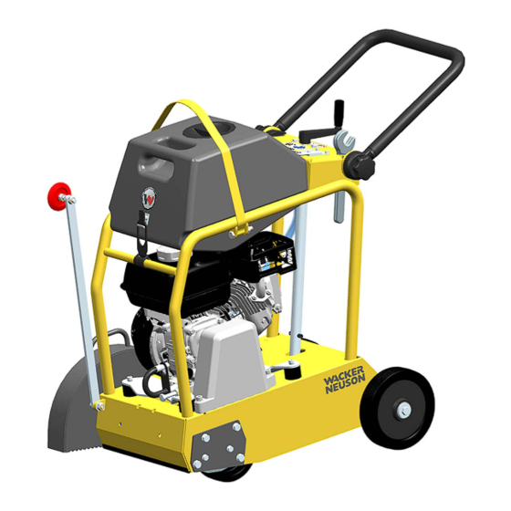
- Page 1 Operator's manual Floor saw Model Document 5100055048 Issue 02.2020 Version Language...
- Page 2 Reproduction or translation, even extracts thereof, only with written approval of Wacker Neuson Any breach of the statutory provisions, in particular the protection of copyright, will lead to civil and criminal prosecution.
- Page 3 CALIFORNIA Proposition 65 Warning WARNING The engine exhaust from this product contains chemicals known to the State of California to cause cancer, birth defects, or other reproductive harm. WARNING Diesel engine exhaust and some of its constituents are known to the State of California to cause cancer, birth defects, and other reproductive harm.
-
Page 5: Table Of Contents
Storage location of the manual ....................6 Accident prevention regulations....................6 More information.......................... 6 Target group ..........................6 Explanation of symbols........................ 6 Wacker Neuson Contact partner ....................7 Disclaimer ............................ 7 Product identification of the machine................... 7 Safety ............................8 Principle ............................8 Qualification of the operating personnel .................. - Page 6 Table of contents Accessories ......................... 39 10.1 Parking brake..........................39 Troubleshooting ........................41 Technical data ........................42 12.1 BFS735............................42 12.2 BFS940............................43 12.3 BFS1345............................ 44 12.4 BFS1350............................ 45 12.5 Combustion engine........................46 Emission control systems information and warranty ............47 ..................48...
-
Page 7: Preface
This operator's manual contains important information and procedures for the safe, proper and economic operation of this Wacker Neuson machine. Carefully reading, understanding and observing is an aid to avoiding hazards, repair costs and downtime, and therefore to increasing the availability and service life of the machine. -
Page 8: Introduction
The information contained in this manual is based on machines manufactured up to the time of printing. Wacker Neuson reserves the right to change this information. The manufacturer shall immediately include any modifications or additions in this manual. -
Page 9: Wacker Neuson Contact Partner
NOTICE Supplementary information. Wacker Neuson Contact partner Depending on the country, the Wacker Neuson contact partner is a Wacker Neuson service department, a Wacker Neuson affiliate, or a Wacker Neuson dealer. On the Internet at www.wackerneuson.com. The manufacturer's address can be found at the beginning of this manual. -
Page 10: Safety
3 Safety Safety Principle State of the art This machine has been constructed with state-of-the-art technology according to the recognized rules of safety. Nevertheless, when used improperly, dangers to the life and limb of the operator or to third persons or damage to the machine or other materials cannot be excluded. - Page 11 Have damaged or defective components replaced immediately! For further information, refer to chapter Troubleshooting. Spare parts, accessories Use only spare parts from Wacker Neuson or such that are equivalent to the original parts in design and quality. Only use accessories from Wacker Neuson.
- Page 12 3 Safety Exclusion of liability Wacker Neuson will refuse to accept liability for injuries to persons or for damage to materials in the following cases: Structural modifications. Improper use. Failure to comply with this operator's manual. Improper handling. Using of spare parts which are not from Wacker Neuson and not equivalent to the original parts in design and quality.
-
Page 13: Qualification Of The Operating Personnel
3 Safety Qualification of the operating personnel Operator qualifications Only trained personnel are permitted to start and operate the machine. The follow- ing rules also apply: You are at least 18 years of age. You are physically and mentally fit. You have received instruction on how to independently operate the machine. -
Page 14: Transport
Before you transport the machine, it must be switched off, and the engine must be given sufficient time to cool down. Emptying the tank Wacker Neuson recommends emptying the fuel tank before transport. Fuel could run out, e.g. if the machine is tilted. Observe the national safety guidelines and the hazardous materials regulations that... -
Page 15: Operating Safety
3 Safety Lifting When lifting the machine, observe the following instructions: Designate a skilled person to guide you for the lifting procedure. You must be able to see or hear this person. Use only suitable and certified hoisting gear, lifting tackle and load-bearing equipment with sufficient lifting capacities. - Page 16 3 Safety Work environment Familiarize yourself with your work environment before you start work. This includes e.g. the following items: Obstacles in the work and traffic area. Load-bearing capacity of the ground. The measures needed to cordon off the construction site from public traffic in particular.
-
Page 17: Safety During The Operation Of Combustion Engines
3 Safety Caution with movable parts Keep your hands, feet and loose clothing away from moving or rotating machine parts. Parts of your body being pulled in or crushed can cause serious injuries. Caution with toxic materials Some materials may contain toxic chemicals which are released during demolition. Therefore personal protective equipment must be worn to prevent inhalation of and skin contact with work dust. - Page 18 3 Safety Dangers during operation Combustion engines can be dangerous, particularly during operation and when re- fueling. Read and follow all safety instructions. Otherwise there is a risk of personal injury and/or damage to property! Do not start the engine near spilt fuel or if you smell fuel – this may cause an explo- sion! Remove the machine from such areas.
-
Page 19: Safety During Floor Saw Operation
This machine is equipped with an EPA-certified engine. Modifying the engine speed influences the EPA certification and emission. The en- gine may only be set by a skilled technician. For more detailed information, contact your nearest engine or Wacker Neuson rep- resentative. Safety during floor saw operation... - Page 20 3 Safety Before ending the wet cutting process, allow the cutting blade to run without the wa- ter sprayer until it is dry. Not exceeding the maximum tilt position Do not exceed the maximum tilt position (see the description in the Maximum permissible tilt chapter).
-
Page 21: Maintenance
Service and maintenance work must only be carried out to the extent described in these operating instructions. All other procedures must be performed by your Wacker Neuson representative. For further information, refer to chapter Maintenance. It is not permitted to tilt the machine for maintenance work. -
Page 22: Safety Devices
If operating fluids escape from the machine, cease operation of the machine and have it repaired immediately by your Wacker Neuson representative. Assembling safety devices If it was necessary to dismantle safety devices, they must be reassembled and checked immediately after completing maintenance work. - Page 23 3 Safety Pos. Description Cutting blade guard Cutting blade guard Never operate the machine without a cutting blade guard. The cutting blade guard performs the following functions: Protects the operator from the rotating cutting blade. Diverts workpiece particles and sparks or chips from a damaged cutting blade away from the operator.
-
Page 24: Safety And Information Labels
4 Safety and information labels Safety and information labels Your machine has adhesive labels containing the most important instructions and safety information. Make sure that all the labels are kept legible. Replace any missing or illegible labels. The item numbers for the labels are in the parts book. Item Label Description... -
Page 25: Scope Of Delivery
5 Scope of delivery Scope of delivery The scope of delivery includes: Floor saw. Open end wrench. Operator's manual. Description Application Cutting expansion joints in concrete and asphalt surfaces. Repair work on streets, e.g. cutting out damaged areas in asphalt and concrete. Straightening blacktops and concrete surfaces. -
Page 26: General Instructions For Use For Diamond-Edged Cutting Blades
Never exceed the maximum speeds (imprinted on cutting blade)! Use a suitable diamond-edged cutting blade for the material to be cut (asphalt, concrete ...). Wacker Neuson offers an extensive range of diamond-edged cut- ting blades in different qualities. Do not cut into the gravel area using diamond-edged cutting blades. When cut- ting on the edge of the track or when cutting two different materials (cutting in the joint area), uneven wear is possible. -
Page 27: Transport To The Worksite
7 Transport to the worksite Transport to the worksite Pos. Description Pos. Description Transport strap Stirrup handle Guide wheel Requirements: When transporting the floor saw, use only suitable hoisting gear with a minimum load-bearing capacity of 150 kg. Always turn off the motor during transportation! Empty the water tank! Remove the cutting blade prior to transport. -
Page 28: Operation
8 Operation Operation Adjusting the handle Pos. Description Star grip (left/right) The height of the stirrup handle can be adjusted according to the use and the body height of the operator. Loosen the star grip on both sides, swivel the handle to the desired position and re- tighten the two star grip. -
Page 29: Cutting Depth Setting
8 Operation Cutting depth setting Pos. Description Pos. Description Crank Receptacle With the crank you can set the cutting depth precisely. One turn changes the cutting depth by exactly 5 mm. Turn the crank in the clockwise direction to increase the cut- ting depth and turn it in the counterclockwise direction to reduce the cutting depth. -
Page 30: Parking Brake
8 Operation Parking brake Integrated parking brake The machine features an integrated parking brake. The front wheels are automatically blocked in transport position (lowest cutting po- sition without a cutting blade) or if the maximum cutting depth is exceeded. Assembling the cutting blade Pos. -
Page 31: Disassembling The Cutting Blade
8 Operation Disassembling the cutting blade Pos. Description Pos. Description Cutting blade guard Water supply Engine Crank Proceed as follows for the disassembly of the cutting blade: 1. Turn off the engine and the water supply. 2. Turn the crank in the counterclockwise direction until the blade is clear of the ground. -
Page 32: Starting The Engine
8 Operation 8.8.2 Fuel Do not smoke during refueling and make sure that there are no open flames or sparks in the immediate vicinity. Turn off the engine and open the fuel tank cap. Only use leadfree fuel. Close the fuel tap before the fuel tank is filled with fuel. Always use the fuel filter when refilling fuel. -
Page 33: Operating The Engine
8 Operation 4. Switch the main switch to "I". 5. Pull the starter handle slowly until you feel resistance and then pull the handle fully out with force. Note: Caution: Do not suddenly let go of the recoil starter handle but guide it back gently by hand to prevent damage to the starter. -
Page 34: Turning Off The Engine
8 Operation 8.11 Turning off the engine To turn off the engine in the event of an emergency, switch the main switch to "0". Under normal circumstances, proceed as follows: Pos. Description Pos. Description Main switch Throttle lever 1. Push the throttle lever backwards as far as it goes. 2. -
Page 35: Maintenance
Idle setting Check idle setting – set if necessary. Spark plug Change. 300 hours (annually) Change. Air cleaner Have this repaired by Wacker Neuson service. Valve clearance Checking engine oil level Turn off the engine. Align the engine bolting level horizontally. -
Page 36: Changing The Engine Oil
9 Maintenance Remove any dirt around the oil level dipstick. Remove the oil level dipstick and wipe it with a clean, lint-free cloth. Screw the oil level dipstick all the way back in and pull it out again. Check: The motor oil level must be between the lower and upper marks. If necessary, pour new engine oil into the opening until the upper mark is reached on the oil level dipstick (see chapter Technical data for oil type). -
Page 37: Cleaning The Filter Cup
9 Maintenance Cleaning the cyclone housing: If dirt accumulates in the cyclone housing, unscrew the three special flat head screws and wipe the components or rinse them with water. Then completely dry off the components and assemble them carefully. Caution: During the reassembly of the cyclone, make sure that the cloth of the air inlet fits properly into the groove of the preliminary filter cap. -
Page 38: Tightening The Belt
Loosen the four fastening nuts of the engine until the engine can be moved with- out play. Tighten the belt with the tension screw. BFS735: Belt tension 00 N (vibration frequency 119 Hz), BFS940/1345/1350: Belt tension 0 N (vibration frequency 98 Hz). -
Page 39: Changing The Belt
6. Screw on the bearing flange (6 screws). 7. Tighten the belt with the tension screw. BFS735: Belt tension 300 N (vibration frequency 119 Hz), BFS940/1345/1350: Belt tension 350 N (vibration frequency 98 Hz). 8. If necessary, correct the parallel alignment of the engine. -
Page 40: Checking The Spark Plug
9 Maintenance Checking the spark plug Remove any soot deposits from the electrodes of the spark plug using a spark plug cleaner or a wire brush. Check the spark plug gap and set it to, if necessary, see chapter Technical Data. Select the correct spark plug, see chapter Technical Data. -
Page 41: 10 Accessories
10 Accessories 10 Accessories There is a wide range of accessories available for the machine. For more information on the individual accessories, visit the following website: www.wackerneuson.com. WARNING Improper handling can result in injury or serious material damage. Read and follow all safety information of this operator's manual, see chapter Safety. - Page 42 10 Accessories Applying the parking brake Item Designation Foot lever Pressure screw 1. Place the machine on a slip-resistant surface that is as flat and even as possible. 2. Press down the foot lever. Note: Check the tight fit of the parking brake and the setting of the pressure screw at regular intervals.
-
Page 43: 11 Troubleshooting
1. Close the fuel tap. The en- main switch is defective. gine will switch off after a few seconds. 2. Have the machine repaired.* * Have these tasks carried out by the service department of your Wacker Neuson contact person. -
Page 44: 12 Technical Data
12 Technical data 12 Technical data 12.1 BFS735 Designation Unit BFS735 Item no. 5100054573 Max. width mm (in) 12 (0.5) Max. cutting depth cm (in) 12 (4.7) Peripheral speed with cutting blade 350 mm (ft/s) 46,0 (150.9) Operating speed of cutting... -
Page 45: Bfs940
12 Technical data 12.2 BFS940 Designation Unit BFS940 Item no. 5100054574 Max. width mm (in) 12 (0.5) Max. cutting depth cm (in) 14.5 (5.7) Peripheral speed with cutting blade 350 mm 40,3(132.2) 400 mm (ft/s) 46,1 (151.2) Operating speed of cutting 2200 blade Length (guide wheel folded... -
Page 46: Bfs1345
12 Technical data 12.3 BFS1345 Designation Unit BFS1345 Item no. 5100054575 Max. width mm (in) 12 (0.5) Max. cutting depth cm (in) 17,0 (6.7) Peripheral speed with cutting blade 350 mm 40,3 (132.2) 400 mm (ft/s) 46,1 (151.2) 450 mm 51,8 (169.9) Operating speed of cutting 2200... -
Page 47: Bfs1350
12 Technical data 12.4 BFS1350 Designation Unit BFS1350 Item no. 5100054576 Max. width mm (in) 12 (0.5) Max. cutting depth cm (in) 19,5 (7.7) Peripheral speed with cutting blade 350 mm 40,3 (132.2) 400 mm (ft/s) 46,1 (151.2) 450 mm 51,8 (169.9) 500 mm 57,6 (189.0) -
Page 48: Combustion Engine
12 Technical data 12.5 Combustion engine Designation Unit BFS735 BFS940 BFS1345 BFS1350 Manufacturer Honda Engine type GX 200 GX 270 GX 390 Combustion method Four-cycle Cooling Air cooling Cylinder Engine displacement 196 (12.0) 270 (16.5) 389 (23.7) Max. tilt position... -
Page 49: 13 Emission Control Systems Information And Warranty
13 Emission control systems information and warranty 13 Emission control systems information and warranty The Emission Control Warranty and associated information is valid only for the U.S.A., its territories, and Canada. Emission control systems warranty statement See the engine owner’s manual for the applicable exhaust and evaporative emission warranty statement. - Page 56 W也C KE� NEUSON...